Dell 1642018871: Hardwiring the UPS Input Figure 4. Circuit Breaker Diagram
Hardwiring the UPS Input Figure 4. Circuit Breaker Diagram: Dell 1642018871
Table of contents
- Notes and Warnings
- System Features
- Finding Information
- Installation and Startup Unpacking the System
- Lifting the Cabinet
- Identifying the UPS Figure 1. The Dell Online Rack UPS Front Panel Figure 2. 5600W, 208V Rear Panel
- Figure 3. 5600W, 230V Rear Panel
- Rackmount Setup Removing the Battery Retaining Bracket
- Removing the Battery Trays
- Installing the Rails
- Installing the Cabinet
- Securing the Cabinet Installing the Battery Trays
- Replacing the Battery Retaining Bracket and Connecting the Internal Battery Connectors
- Installing the UPS Front Cover Connecting the Equipment
- Hardwiring the UPS Input Figure 4. Circuit Breaker Diagram
- Removing the Terminal Block Cover
- Installing the Input and Ground Wires Table 1. UPS Wiring Specifications
- Starting the UPS
- Completing the Startup
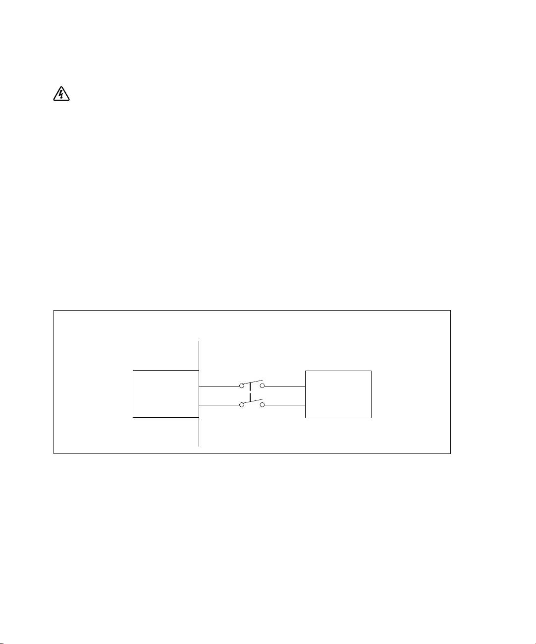
Hardwiring the UPS Input
WARNING: Only qualified service personnel (such as a licensed electrician) shall perform the electrical
installation. Risk of electrical shock.
The UPS requires a dedicated branch circuit that meets the following requirements:
S The protection device requires a two-pole disconnection device between the UPS output and the
load (see Figure 4)
S The breaker must be wall-mounted and be readily accessible to the operator
S For Europe, the breaker must meet the IEC/EN 60934 standard and have a contact air gap of at
least 3 mm
S 200–240 Vac
S Single-phase
- 5600W/208V model is phase-to-phase
- 5600W/230V model is phase-to-neutral
S 50/60 Hz
S Flexible metal conduit (recommended for ease of service and maintenance)
Wall
2-pole
Breaker
Line
AC Mains
UPS
Neutral/L2
Figure 4. Circuit Breaker Diagram
16
|
Installation and Startup
