Beurer TL 30 – page 4
Manual for Beurer TL 30
Table of contents
- 1. About the daylight lamp 2. Signs and symbols
- 3. Notes Safety notes General notes
- Repairs 4. Unit description Overview 5. Initial use 6. Operation 1 2 3 Switching on the lamp
- 4 Enjoying the light 5 Important instructions 6 Enjoying light over longer periods 7 Switching off the lamp 7. Cleaning and care of the unit 8. Storage
- 9. Disposal 10. What if there are problems? 11. Technical specifications
- 12. Mains part
7. Czyszczenie i konserwacja urządzenia
Od czasu do czasu należy czyścić urządzenie.
Uwaga
• Uważać, aby woda nie dostała się do środka urządzenia!
Przed każdym czyszczeniem należy wyłączyć urządzenie, odłączyć od sieci i poczekać, aż ostygnie.
• Nie czyścić urządzenia w zmywarce!
W celu czyszczenia należy używać lekko wilgotnej szmatki.
• Podłączonego urządzenia nie wolno dotykać wilgotnymi dłońmi; krople wody nie mogą rozpryskiwać się
na urządzeniu. Można użytkować wyłącznie całkowicie suche urządzenie.
Nie używać żrących środków czyszczących i nigdy nie myć urządzenia pod bieżącą wodą.
8. Wymiana świetlówek
Jeśli urządzenie nie jest używane przez dłuższy czas, należy je przechowywać odłączone od sieci w suchym
miejscu, tak aby dzieci nie miały do niego dostępu.
Należy przestrzegać warunków przechowywania opisanych w rozdziale „Dane techniczne”.
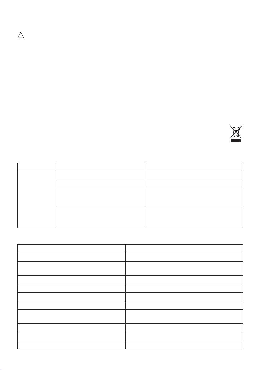
9. Utylizacja
Ze względu na ochronę środowiska po zakończeniu użytkowania urządzenia nie wolno wyrzucać z od
-
padami domowymi. Utylizację należy zlecić w odpowiednim punkcie zbiórki w danym kraju. Urządzenie
należy zutylizować zgodnie z dyrektywą WE o zużytych urządzeniach elektrycznych i elektronicznych
– WEEE (Waste Electrical and Electronic Equipment). W razie pytań należy zwrócić się do odpowiedniej
instytucji odpowiedzialnej za utylizację.
10. Co robić wprzypadku problemów?
Problem Możliwa przyczyna Rozwiązanie
Urządzenie nie
Wyłączony przycisk Wł./Wył. Naciśnij przycisk włączania/wyłączania.
świeci się
Brak prądu Podłączyć prawidłowo zasilacz.
Brak prądu Zasilacz jest uszkodzony. Należy skontakto
-
wać się z działem obsługi klienta lub sprze-
dawcą.
Przekroczono okres użytkowania diod
Konieczność dokonania jakichkolwiek napraw
LED. Uszkodzenie diod LED.
należy zgłosić w serwisie lub autoryzowanemu
przedstawicielowi handlowemu.
11. Dane techniczne
Nr modelu TL 30
Typ WL 11
Wymiary (szer. x wys. x gł.) 236 x 156 x 20 mm (z miejscem przechowywania nóżki
26 mm)
Ciężar 175 g (260 g z zasilaczem + pokrowcem)
Oprawa oświetleniowa LED
Moc 5 wat
Natężenie oświetlenia 10.000 luksów (10 cm)
Promieniowanie Moc promieniowania spoza zakresu widzialnego
(poczerwień i UV)
Warunki robocze 0°C do 35°C, względna wilgotność powietrza 15–90%
Warunki przechowywania -20°C do 50°C, względna wilgotność powietrza 15–90%
Klasyfikacja produktu zewnętrzny zasilacz, Klasa bezpieczeństwa II, IP21
61
Temperatura barwowa świetlówek 6.500 kelwinów
Zakres dostawy Lampa o świetle dziennym, Nóżka, Pokrowiec, Niniejsza
instrukcja obsługi, Zasilacz
Zastrzegamy sobie prawo do zmian technicznych.
Niniejsze urządzenia odpowiada wymogom europejskich dyrektyw dla produktów medycznych 93/42/EWG i
2007/47/EWG oraz przepisom dotyczącym produktów medycznych.
Urządzenie spełnia europejską normę EN60601-1-2 iwymaga zachowania szczególnych środków ostrożności
dotyczących kompatybilności elektromagnetycznej. Należy pamiętać, że przenośne urządzenia komunikacyjne
pracujące na wysokich częstotliwościach mogą zakłócać działanie urządzenia. Dokładniejsze dane można uzy
-
skać po skontaktowaniu się z działem obsługi klienta pod podanym poniżej adresem. Dane znajdują się także na
końcu instrukcji obsługi.
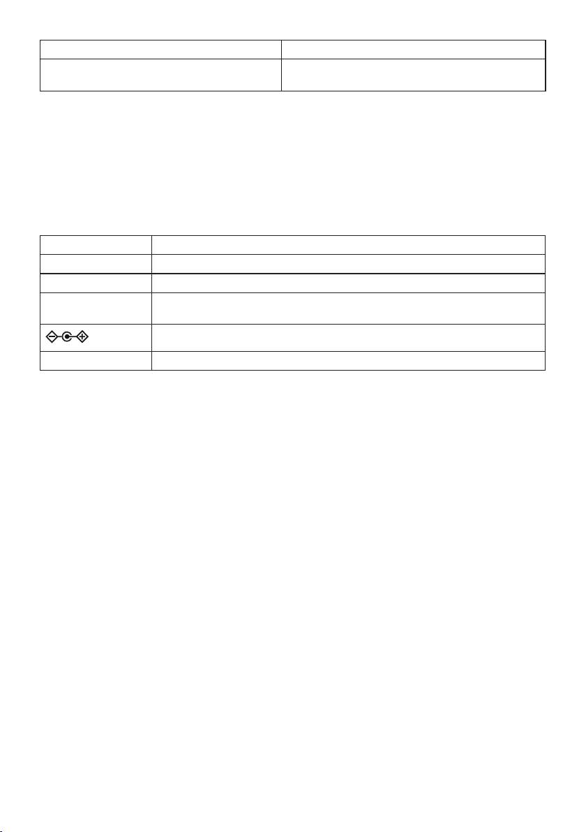
12. Zasilacz
Nr modelu EE 16-08
Wejście 100–240 V ~ 50/60 Hz
Wyjście 12 V DC, 650 mA, tylko w połączeniu z TL 30
Ochrona Urządzenie posiada podwójną izolację ochronną i jest zgodne tym samym z klasą
ochronności II
Biegunowość przyłącza napięcia stałego
Klasyfikacja IP22, klasą ochronności II
62
ELECTROMAGNETIC COMPATIBILITY INFORMATION
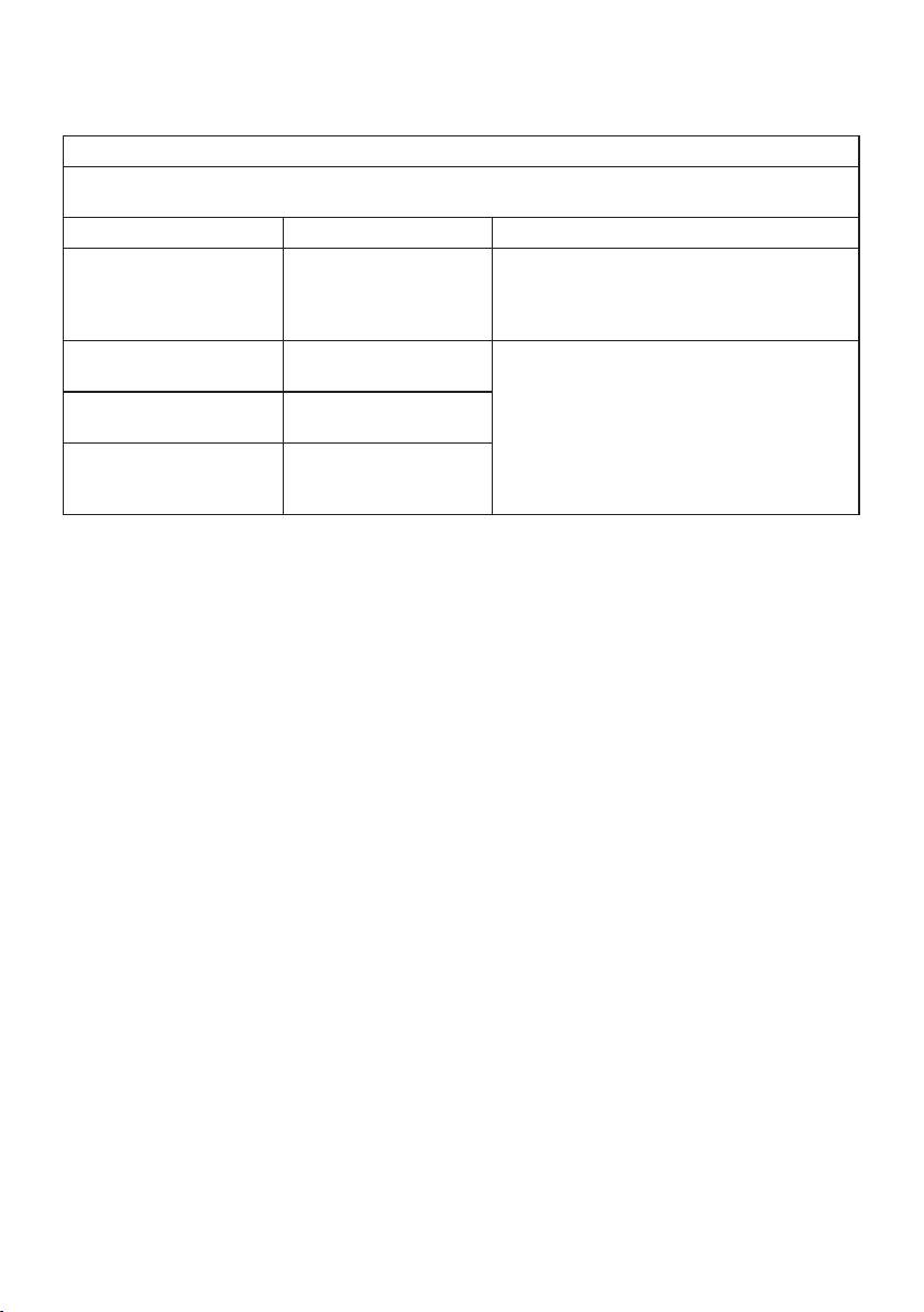
Technical Description Concerning Electromagnetic Emission
Table 1: Declaration - electromagnetic emissions
Guidance and manufacturer’s declaration - electromagnetic emissions
The model TL30 is intended for use in the electromagnetic environment specified below.
The customer or the user should assure that it is used in such an environment.
Emissions test Compliance Electromagnetic environment – guidance
RF emissions
Group 1 The models TL30 use RF energy only for its inter
-
CISPR 11
nal function. Therefore, its RF emissions are very
low and are not likely to cause any interference in
nearby electronic equipment.
RF emissions
Class B The model TL30 is suitable for used in domestic
CISPR 11
establishment and in establishment directly con
-
nected to a low voltage power supply network
Harmonic emissions
Class C
which supplies buildings used for domestic
IEC 61000-3-2
purposes.
Voltage fluctuations/
Not applicable
flicker emissions
IEC 61000-3-3
63

Technical Description Concerning Electromagnetic Emission
Table 1: Declaration - electromagnetic emissions
Guidance and manufacturer’s declaration – electromagnetic immunity
The model TL30 is intended for use in the electromagnetic environment specified below.
The customer or the user should assure that It is used in such an environment.
Immunity test IEC 60601
Compliance
Electromagnetic environment –
test level
level
guidance
Electrostatic
±6 kV contact
±6 kV contact
Floors should be wood, concrete
discharge (ESD)
±8 kV air
±8 kV air
or ceramic tile. If floors are covered
lEC 61000-4-2
with synthetic material, the relative
humidity should be at least 30 %.
Electrical fast
±2 kV for power
±2 kV for power
Mains power quality should be that
transient/burst
supply lines
supply lines
of a typical commercial or hospital
IEC 61000-4-4
±1 kV for input/output
environment.
lines
Surge
±1 kV line to line
±2 kV line to earth Mains power quality should be that
lEC 61000-4-5
±2 kV line to earth
of a typical commercial or hospital
environment.
Voltage dips,
<5 % U
(>95% dip in U
)
<5 % U
(>95% dip in U
)
Mains power quality should be that
T
T
T
T
short interrup
-
for 0.5 cycle
for 0.5 cycle
of a typical commercial or hospital
tions and vol-
40 % U
(60% dip in U
)
40 % U
(60% dip in U
)
environment. If the user of the
T
T
T
T
tage variations
for 5 cycles
for 5 cycles
model TL30 require continued ope
-
on power supp
-
70% U
(30% dip in U
)
70% U
(30% dip in U
)
ration during power mains interrup-
T
T
T
T
ly input lines
for 25 cycles
for 25 cycles
tions, it is recommended that the
IEC 61000-4-11
<5% U
(>95 % dip in U
)
<5% U
(>95 % dip in U
)
model 168 DAYLUX Therapy Light
T
T
T
T
for 5 sec
for 5 sec
be powered from an uninterruptible
power supply or a battery.
Power frequen
-
3 A/m Not applicable Not applicable
cy (50/60 Hz)
magnetic field
lEC 61000-4-8
NOTE U
is the a.c. mains voltage prior to application of the test level.
T
64
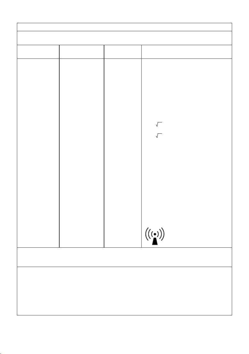
Table 3: Guidance & Declaration - electromagnetic immunity concerning Conducted RF & Radiated RF
Guidance and manufacturer’s declaration – electromagnetic immunity
The model TL30 is intended for use in the electromagnetic environment specified below.
The customer or the user should assure that it is used in such an environment.
Immunity test IEC 60601
Compliance
Electromagnetic environment –
test level
level
guidance
Portable and mobile RF communications
equipment should be used no closer to any
part of the model TL30, including cables,
than the recommended separation distance
calculated from the equation applicable to
the frequency of the transmitter.
Recommended separation distance
3 V
rms
3 V
3V
150 kHz to 80 MHz
Conducted RF lEC
d=1.2 P 80MHz to 800MHz
61000-4-6
Radiated RF lEC
3 V/m
3 V/m
d=2.3 P 800MHz to 2.5 GHz
61000-4-3
80 MHz to 2.5 GHz
where P is the maximum output power rating
of the transmitter In watts (W) according to
the transmitter manufacturer and d Is the
recommended separation distance in meters
(m).
Field strengths from fixed RF transmitters,
as determined by an electromagnetic site
a
survey,
should be less than the compliance
b
level in each frequency range.
Interference may occur In the vicinity of
equipment marked with the following sym
-
bol:
symbol:
65
NOTE 1 At 80 MHz end 800 MHz. the higher frequency range applies.
NOTE 2 These guidelines may not apply in all situations. Electromagnetic propagation is affected by absorpti
-
on and reflection from structures, objects and people.
a
Field strengths from fixed transmitters, such as base stations for radio (cellular/cordless) telephones and land
mobile radios, amateur radio, AM and FM radio broadcast and TV broadcast cannot be predicted theoreti
-
cally with accuracy. To assess the electromagnetic environment due to fixed RF transmitters, an electroma-
gnetic site survey should be considered. If the measured field strength in the location in which the model
TL30 is used exceeds the applicable RF compliance level above, the model TL30 should be observed to
verify normal operation. If abnormal performance is observed, additional measures may be necessary, such
as reorienting or relocating the model TL30.
b
Over the frequency range 150 kHz to 80 MHz, field strengths should be less than 3V/m.
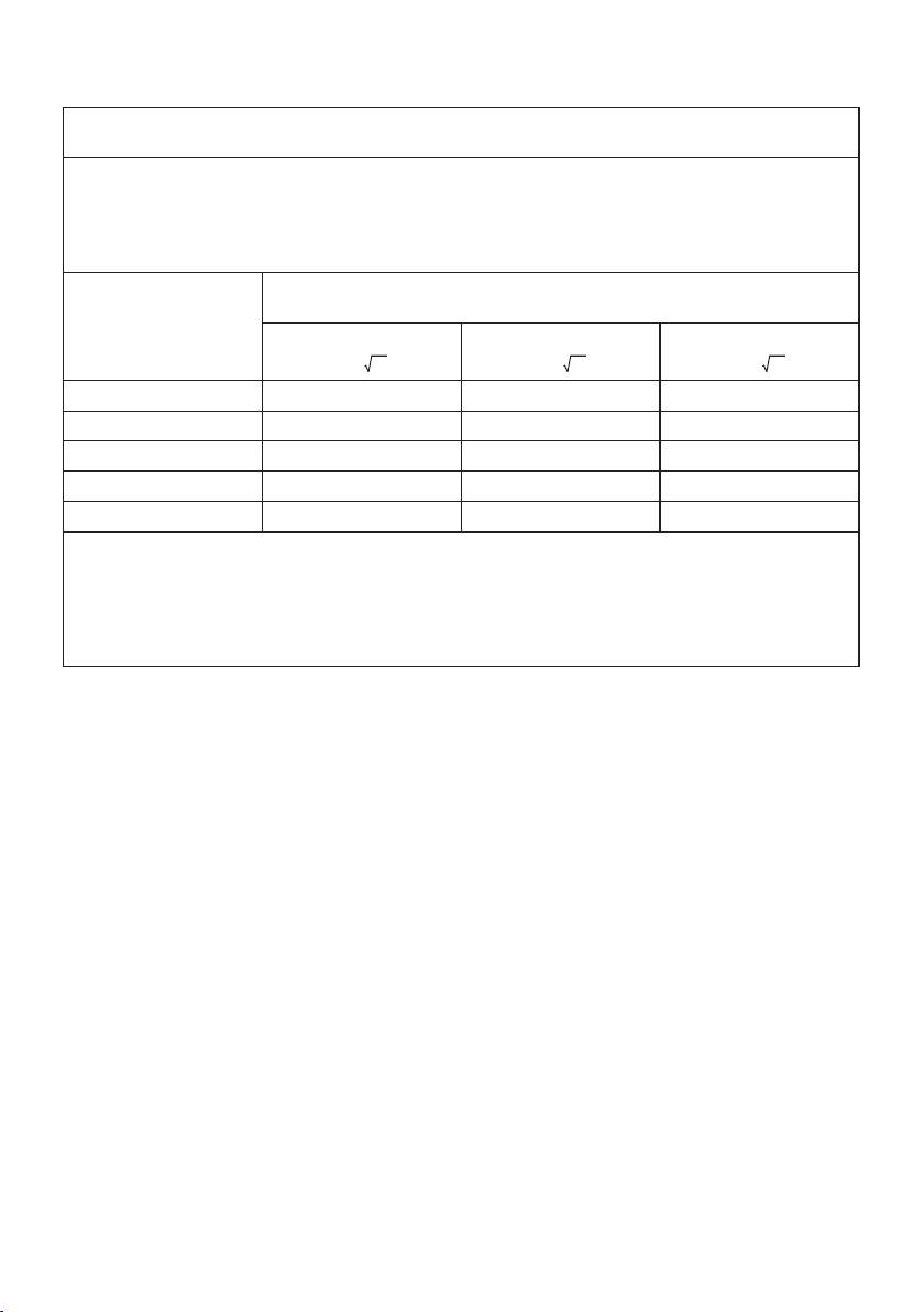
Table 4: Recommended separation distances between portable and mobile RF communications
equipment and the model TL30
Recommended separation distances between
portable and mobile RF communications equipment and the model TL30
The model TL30 is intended for use in electromagnetic environment in which radiated RF disturbances is
controlled. The customer or the user of the model TL30 can help prevent electromagnetic interference by
maintaining a minimum distance between portable and mobile RF communications equipment (transmitters)
and the model TL30 as recommended below, according to the maximum output power of the communications
equipment.
Rated maximum output
Separation distance according to frequency of transmitter
power of transmitter
m
W
150 kHz to 80 MHz
80 MHz to 800 MHz
800 MHz to 2,5 GHz
1.2 P
1.2 P
2.3 P
0.01 0.12 0.12 0.23
0.1 0.38 0.38 0.73
1 1.2 1.2 2.3
10 3.8 3.8 7.3
100 12 12 23
For transmitters rated at a maximum output power not listed above, the recommended separation distance d
in meters (m) can be estimated using the equation applicable to the frequency of the transmitter, where P is
the maximum output power rating of the transmitter in watts (W) accordable to the transmitter manufacturer.
NOTE 1 At 80 MHz and 800 MHz. the separation distance for the higher frequency range applies.
NOTE 2 These guidelines may not apply in all situations. Electromagnetic propagation is affected by absorpti
-
on and reflection from structures, objects and people.
66

67

751.695-1014 Irrtum und Änderungen vorbehalten
68
