Konig Electronic Tone generator with amplifier probe: инструкция
Раздел: Телевизоры и цифровое ТВ
Тип:
Инструкция к Konig Electronic Tone generator with amplifier probe
CMP-RCT11
MANUAL (p. 2)
ANLEITUNG (S. 5)
Tone generator and probe
Tongenerator und Sonde
MODE D’EMPLOI (p. 8)
GEBRUIKSAANWIJZING (p. 11)
Générateur de tonalité et sonde
Toongenerator en sonde
amplificatrice
MANUALE (p. 14)
MANUAL DE USO (p. 17)
Rilevatore e generatore di toni
Generador de tono y sonda
HASZNÁLATI ÚTMUTATÓ (o. 20.)
KÄYTTÖOHJE (s. 23)
Hanggenerátor és szonda
Äänigeneraattori ja anturi
BRUKSANVISNING (s. 26)
NÁVOD K POUŽITÍ (s. 29)
Tongenerator och sond
Tónový generátor se sondou
MANUAL DE UTILIZARE (p. 32)
ΕΓΧΕΙΡΙ∆ΙΟ XPHΣHΣ (σελ. 35)
Generator de ton şi sondă
Γεννήτρια τόνων και ανιχνευτής
BRUGERVEJLEDNING (s. 38)
VEILEDNING (s. 41)
Signalgenerator og føler
Tonegenerator og sonde
ИНСТРУКЦИЯ (стр. 44)
Генератор тона и пробник
2013-01-14
ENGLISH
Tone generator and probe
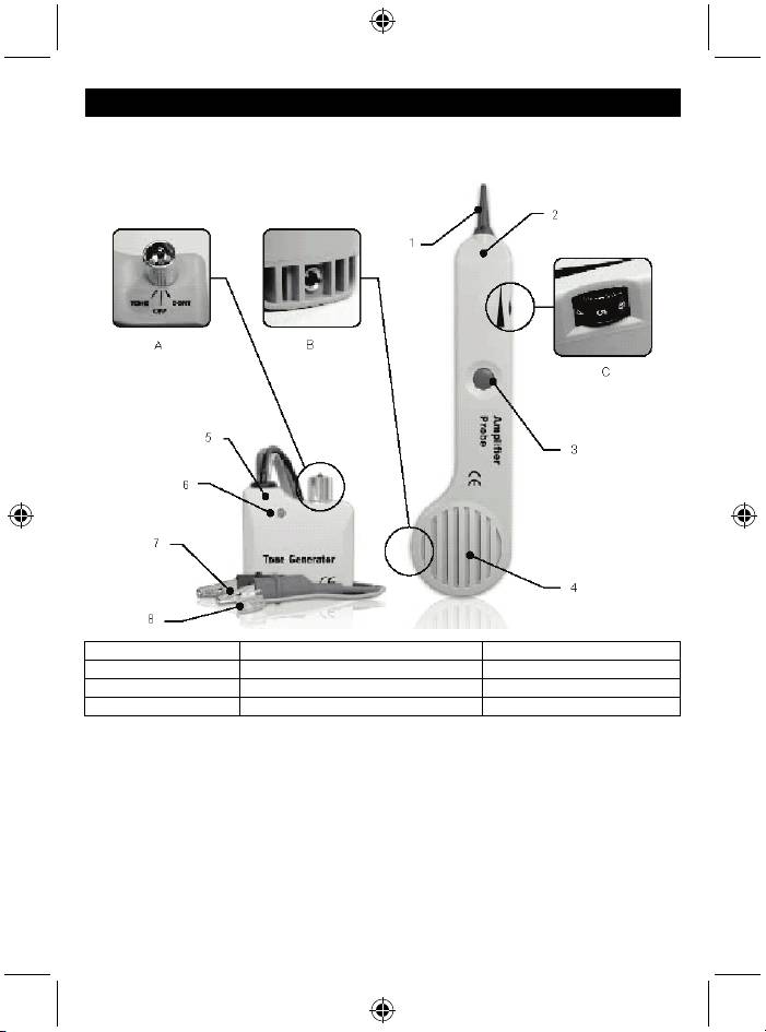
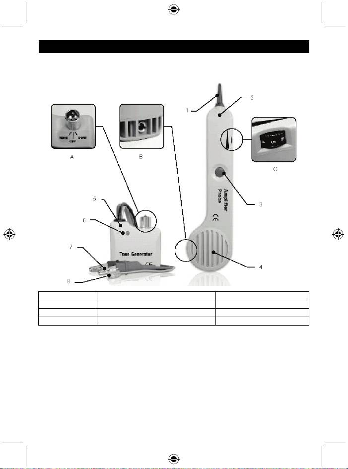
Device explanation:
1. Tip 5. Tone generator A. 3 position toggle switch
2. Amplifier probe 6. DUAL COLOUR LED B. Phone jack
3. Test button 7. Red and black test leads C. Volume control
4. Speaker 8. 4 conductor modular cord and plug
Instructions:
• Overall instructions:
1. Connecting the tone generator.
In terminated working cables:
Connect one test lead to a terminated wire and the other test lead to an earth or equipment
ground.
In unterminated or non-working cables:
Connect one test lead to an unterminated wire and the other test lead to another unterminated
wire.
2. Depress the round on/off button of the amplifier probe. The volume control switch can be
adjusted to suit the environment. Volume can be increased to overcome noise, or decreased to
reduce interference.
2
3. Touch the tip of the amplifier probe to the insulation of each suspect conductor.
4. Reception of the tone will be loudest on the subject wire.
5. The plug receptacle is provided to be connected to a headset or handset.
• Identifying tip and ring (switch to “Off”):
1. Connect the RED test lead to one line and the BLACK lead to the other line.
2. The LED will glow GREEN when you connect the RED test lead to the RING SIDE of the line.
3. The LED will glow “RED” when you connect the RED test lead to the TIP SIDE of the line.
• Identifying line condition (switch to “OFF”):
1. Connect the RED test lead to the RING SIDE of the line and the BLACK lead to the TIP.
2. Watch the LED:
a. A bright green LED indicates a clear line
b. No light indicates a busy line
c. A brightly flickering YELLOW light indicates a RINGING line
• Verifying lines (switch to “OFF” then “CONT”):
1. Dial the line to be verified.
2. While the line is ringing, connect the RED lead to the RING SIDE of the line and the BLACK
lead to the TIP.
3. In the “Off” position, the indicator light will flicker YELLOW when the test leads are connected to
the subject pair.
4. If you switch the test set to “CONT”, it will terminate the call on the subject line.
• Sending tone (switch to “TONE”):
(Caution: Do not connect to an active AC circuit exceeding 24V in this mode)
1. Connect the test leads to the pair, or attach one lead to ground and one lead to either side of the
line.
2. A dual alternating tone, or a single solid tone, can be selected from the switch inside the tone
generator.
3. Probe the suspected wires with the amplifier probe. Reception of the tone will be strongest on
the subject wire. In the case of ready access to bare conductors, a handset or headset may be
used to receive the tone.
• Testing continuity (switch to “CONT”):
(Caution: Do not connect to an active AC or DC circuit in this mode)
1. Connect the test leads to the subject pair.
2. Use “CONT” position.
3. A bright GREEN light indicates continuity. The LED will not glow if the line resistance exceeds
10,000 Ω.
• Testing continuity using tone (switch to “TONE”):
(Caution: Do not connect to an active AC or DC circuit in this mode)
1. Connect the test leads to the subject pair.
2. Use a handset or headset at the remote end and touch the wire end(s) with the clip lead(s).
3. Reception of the tone is an indication of continuity.
• Modular testing:
1. All of the above tests are available through the modular plug for line 1 only – red and green
wires.
3
• Coax testing:
1. To test unterminated coax, connect the red lead to the outer shield and the black lead to the
centre conductor or the red lead to the outer shield and the black lead to the ground.
2. To test the terminated coax, connect the red lead to the connector housing and the black lead to
the centre pin or the red lead to the connector housing and the black lead to the ground.
• Battery replacement:
1. The amplifier probe is maintenance free except for the battery replacement.
Remove the screw from the battery compartment, replace the 9 V battery and screw the lid
back on.
Safety precautions:
Do not expose the product to water or moisture.
DO NOT CONNECT TO AN ACTIVE AC CIRCUIT EXCEEDING 24 V IN THIS MODE.
Maintenance:
Clean the product only with a dry cloth.
Do not use cleaning solvents or abrasives.
Warranty:
Any changes and/or modifications to the product will void the warranty. We cannot accept any liability
for damage caused by incorrect use of this product.
Disclaimer:
Designs and specifications are subject to change without prior notice. All logos, brands and product
names are trademarks or registered trademarks of their respective holders and are hereby recognised
as such.
Disposal:
• This product is designated for separate collection at an appropriate collection point. Do not
dispose of this product with household waste.
• For more information, contact the retailer or the local authority responsible for waste
management.
4
DEUTSCH
Tongenerator und Sonde
Gerätebeschreibung:
1. Spitze 5. Tongenerator A. Kippschalter mit 3 Positionen
2. Verstärkersonde 6. ZWEIFARBIGE LED B. Telefonanschluss
3. Test-Taste 7. Rote und schwarze Testkabel C. Lautstärkeregler
4. Lautsprecher 8. 4 Leiter modulare Leitung und Stecker
Anleitungen:
• Allgemeine Anleitungen:
1. Tongenerator anschließen.
An konfektionierten Arbeitskabeln:
Schließen Sie ein Testkabel an ein konfektioniertes Kabel und das andere Testkabel erden oder
am Ausrüstungsboden erden.
An nicht-konfektionierten oder nicht-Arbeitskabeln:
Schließen Sie ein Testkabel an ein nicht-konfektioniertes Kabel und das andere Testkabel an
das andere nicht-konfektionierte Kabel an.
2. Drücken Sie die runde, federbelastete EIN/AUS Taste der Verstärkersonde. Der
Lautstärkeregler kann passend zum Umfeld eingestellt werden. Die Lautstärke kann erhöht
5
werden, um die Geräusche zu übertönen oder sie kann verringert werden, um die Störungen zu
verringern.
3. Berühren Sie die Spitze der Verstärkersonde zur Isolation von jedem Fehlerverdächtigen Leiter.
4. Der Tonempfang ist auf dem betreffenden Kabel am lautesten.
5. Die Steckerbuchse wird zum Anschluss an einen Kopfhörer oder Handapparat vorgesehen.
• Spitze und Ring kenntlich machen (auf „Off“ schalten):
1. Schließen Sie das ROTE Testkabel am Ende einer Leitung und das SCHWARZE Kabel am
anderen Ende der Leitung an.
2. Die LED leuchtet GRÜN, wenn Sie das ROTE Testkabel an das Ringende der Leitung
anschließen.
3. Die LED leuchtet ROT, wenn Sie das ROTE Testkabel an der Spitzenseite der Leitung
anschließen.
• Leitungszustand erkennen (auf „Off“ schalten):
1. Schließen Sie das ROTE Testkabel am RINGENDE einer Leitung und das SCHWARZE Kabel
an der SPITZE an.
2. Sehen Sie auf die LED:
a. Eine hell grüne LED zeigt eine klare Linie an
b. Eine besetzte Leitung wird nicht durch Licht angezeigt
c. Ein hell flackerndes GELBES Licht zeigt die LÄUTENDE Leitung an
• Leitungen prüfen (auf „OFF“ und dann auf „CONT“ schalten):
1. Wählen Sie die zu prüfende Leitung aus.
2. Schließen Sie das ROTE Testkabel auf der LÄUTENDEN SEITE einer Leitung und das
SCHWARZE Kabel an der SPITZE an.
3. In der Position „Off“ blinkt das Anzeigelicht GELB, wenn die Testkabel an das betreffende Paar
angeschlossen werden.
4. Wenn Sie den Testsatz auf „CONT“ schalten, wird der Anruf auf der betreffenden Leitung
beendet.
• Sendeton (auf „TONE“ schalten):
(Achtung: Nicht an einen aktiven Wechselstromkreis anschließen, der in diesem Modus 24V
übersteigt)
1. Schließen Sie die Testkabel an das Paar an oder erden Sie ein Kabel auf jeder Seite der
Leitung.
2. Ein zweifacher Wechselton oder ein einzelner Dauerton können mit dem Schalter in dem
Tongenerator ausgewählt werden.
3. Untersuchen Sie die verdächtigen Kabel mit der Verstärkersonde. Der Empfang des Tons ist
auf dem betreffenden Kabel am lautesten. Im Falle des freien Zugangs auf die blanken Leiter
kann ein Handapparat oder ein Kopfhörer verwendet werden, um den Ton zu empfangen.
• Kontinuität testen (auf „CONT“ schalten):
(Achtung: In diesem Modus nicht an einen aktiven Wechselstrom- oder Gleichstomkreis
anschließen)
1. Schließen Sie die Testkabel an das betreffende Paar an.
2. Verwenden Sie die Position „CONT“.
3. Ein hell GRÜNES Licht zeigt Kontinuität an. Die LED leuchtet nicht, wenn der Kabelwiderstand
10.000 Ω übersteigt.
6
• Kontinuität mit einem Ton testen (auf „TONE“ schalten):
(Achtung: In diesem Modus nicht an einen aktiven Wechselstrom- oder Gleichstomkreis
anschließen)
1. Schließen Sie die Testkabel an das betreffende Paar an.
2. Verwenden Sie einen Handapparat oder einen Kopfhörer an der Fernseite und berühren Sie
das/die Kabelende(n) mit den/der Klemme(n).
3. Der Empfang des Tons ist eine Anzeige der Kontinuität.
Modularer Test:
1. Alle obigen Tests stehen durch den modularen Stecker nur für Leitung 1 - rote und grüne
Kabel - zur Verfügung.
• Koaxialkabel-Test:
1. Um ein unkonfektioniertes Koaxialkabel zu testen, schließen Sie das rote Kabel an den
äußeren Schirm und das schwarze Kabel an den mittleren Leiter oder an den äußeren Schirm
und das schwarze an die Erdung an.
2. Um ein unkonfektioniertes Koaxialkabel zu testen, schließen Sie das rote Kabel an das
Anschlussgehäuse und das schwarze Kabel an den mittleren Stift oder das rote Kabel an das
Anschlussgehäuse und das schwarze Kabel an die Erdung an.
Batteriewechsel:
1. Die Verstärkersonde ist abgesehen von dem Batteriewechsel wartungsfrei.
Schrauben Sie die Schrauben des Batteriefachs ab, wechseln Sie die 9V Batterie aus und
bauen Sie das Gerät wieder zusammen.
Sicherheitsvorkehrungen:
Stellen Sie sicher, dass das Gerät nicht mit Wasser oder Feuchtigkeit in Berührung kommt.
NICHT AN EINEN AKTIVEN WECHSELSTROMKREIS ANSCHLIESSEN, DER IN DIESEM MODUS
24V ÜBERSTEIGT.
Wartung:
Reinigen Sie das Gerät nur mit einem trockenen Tuch.
Keine Reinigungs- oder Scheuermittel verwenden.
Garantie:
Alle Änderungen und/oder Modifizierungen an dem Produkt werden ein Erlöschen der Garantie zur
Folge haben. Wir übernehmen keine Haftung für Schäden durch unsachgemäße Verwendung dieses
Produkts.
Haftungsausschluss:
Design und technische Daten können ohne vorherige Ankündigung geändert werden. Alle Logos,
Marken und Produktnamen sind Marken oder eingetragene Marken ihrer jeweiligen Eigentümer und
werden hiermit als solche anerkannt.
Entsorgung:
• Dieses Produkt muss an einem entsprechenden Sammelpunkt zur Entsorgung abgegeben
werden. Entsorgen Sie dieses Produkt nicht mit dem Haushaltsmüll.
• Weitere Informationen erhalten Sie beim Verkäufer oder der für die Abfallwirtschaft
verantwortlichen örtlichen Behörde.
7
