Konig Electronic WLAN router 300 Mbps: инструкция
Раздел: Бытовая, кухонная техника, электроника и оборудование
Тип: Компьютер
Инструкция к Компьютеру Konig Electronic WLAN router 300 Mbps
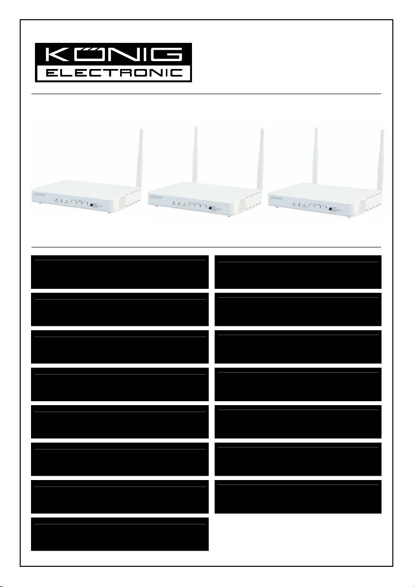
CMP-WNROUT50
CMP-WNROUT55
CMP-WNROUT60
MANUAL (p. 2)
ANLEITUNG (S. 48)
Wireless router
WLAN-Router
MODE D’EMPLOI (p. 96)
GEBRUIKSAANWIJZING (p. 145)
Routeur sans fil
Draadloze router
MANUALE (p. 193)
MANUAL DE USO (p. 241)
Router Wireless
Router inalámbrico
HASZNÁLATI ÚTMUTATÓ (o. 289.)
KÄYTTÖOHJE (s. 336)
Vezeték nélküli útválasztó
Langaton reititin
BRUKSANVISNING (s. 383)
NÁVOD K POUŽITÍ (s. 431)
Trådlös router
Bezdrátový router
MANUAL DE UTILIZARE (p. 479)
ΕΓΧΕΙΡΙΔΙΟ XPHΣHΣ (σελ. 526)
Ruter wireless
Ασύρματο ρούτερ
BRUGERVEJLEDNING (s. 576)
VEILEDNING (s. 624)
Trådløs router
Trådløs ruter
ИНСТРУКЦИЯ (стр. 671)
Беспроводной маршрутизатор
2013-01-29
ENGLISH
Wireless router
1) HARDWARE CONFIGURATION
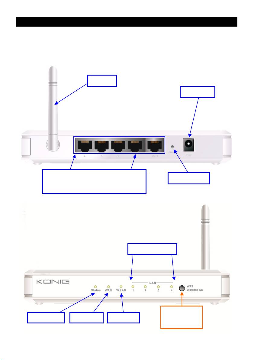
CMP-WNROUT50
Antenna
Power Jack
Auto MDI/MDIX RJ-45 Ports
Reset Button
Automatically senses the types of WAN and
LAN when connecting to the Ethernet
LAN1~LAN4 LEDs
2 in 1 Button
Status LED WAN LED Wi-Fi LED
1. WPS
2. Wireless On
2

LED INDICATORS
LED status Description
Status Green flash Device status is working
Green RJ45 cable is plugged in
WAN LED
Green flash Data access
Green RJ45 cable is plugged in
LAN LED
Green flash Data access
Green Wi-Fi is on
Green flash Data access
Wi-Fi LED
Green fast flash Device is in WPS PBC mode
Dark green Wi-Fi is disabled
BUTTON DEFINITION
Description
1. When wireless is switched off, press and hold this button for about 1 second to
enable “wireless radio”.
WPS
2. When wireless is switched on, press and hold this button for about 1 second to
execute WPS function.
Reset Press and hold for 6 seconds to reset to default settings
3
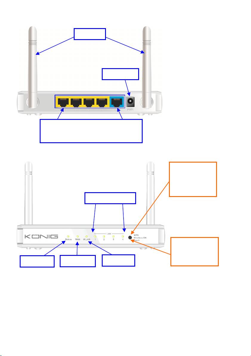
CMP-WNROUT55 and CMP-WNROUT60
Antenna
Power Jack
Auto MDI/MDIX RJ-45 Ports
Automatically senses the types of WAN and
LAN when connecting to the Ethernet
CMP-WNROUT55
3 in 1 Button
1. WPS
2. Wireless ON
3. Reset
LAN1~LAN4 LEDs
CMP-WNROUT60
2 in1 Button
1. WPS
Status LED
WAN LED
Wi-Fi LED
2. Wireless On
4

LED INDICATORS
LED status Description
Status Green flash Device status is working
Green RJ45 cable is plugged in
WAN LED
Green flash Data access
Green RJ45 cable is plugged in
LAN LED
Green flash Data access
Green Wi-Fi is on
Green flash Data access
Wi-Fi LED
Green fast flash Device is in WPS PBC mode
Dark green Wi-Fi is disabled
BUTTON DEFINITION
Description
CMP-WNROUT55
When wireless is switched on, press and hold this button (about 1 sec) to execute
WPS function
WPS
CMP-WNROUT60
1. When wireless is switched off, press and hold this button (about 1 sec) to
enable “Wireless Radio”
2. When wireless is switched on, press and hold this button (about 1 sec) to
execute WPS function
Wireless On
When wireless is switched off, press and hold this button (about 1 sec) to enable
(CMP-WNROUT55
“Wireless Radio”
only)
CMP-WNROUT55
1. Press this button and switch on the device
2. Press and hold for about 3 – 4 seconds. The device will reset to the default
settings. Then the Status LED flashes every second in Normal status
Reset
Notice: If the Status LED flashes very fast, it means this button was pressed too
long. Please try again
CMP-WNROUT60
Press and hold this button for 6 seconds to reset to default settings. Release the
button when the device works simultaneously.
5
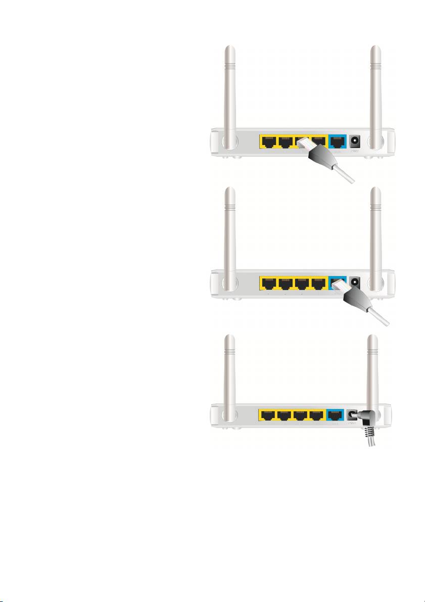
2) HOW TO OPERATE
Step 1. Insert the Ethernet cable into the LAN
Port:
Insert one end of the Ethernet patch cable into
the LAN port on the back panel of the router, and
the other end into an available Ethernet port on
the network adapter of the computer you will use
to configure the unit.
Step 2. Insert the Ethernet patch cable into
the wired WAN port:
Insert the Ethernet patch cable from the DSL
modem into the wired WAN port on the back
panel of the router.
Step 3. Power on the router:
Connect the power adapter to the receptor on the
back panel of your router.
Step 4. Complete the setup.
6
Insert the CD into the CD-ROM reader of your PC. The program, AutoRun, will be executed
automatically. Click the Easy Setup icon for this utility.
Configure the settings by following the steps below:
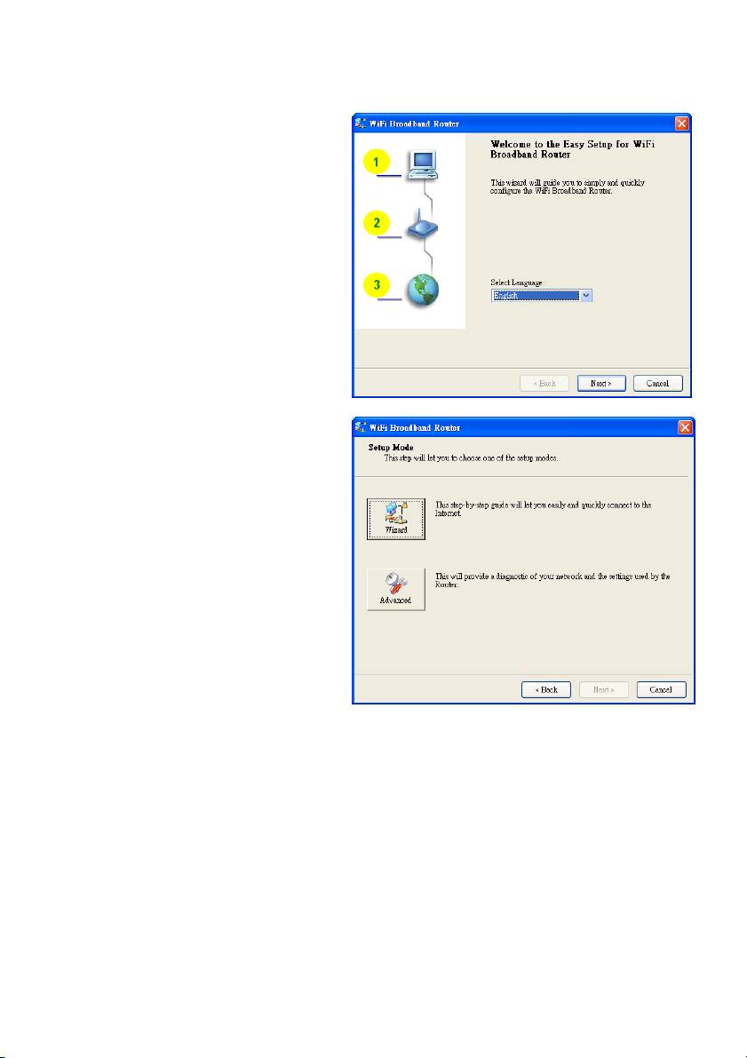
2.1
Select the correct language and click “Next” to
continue.
2.2 Setup Mode
You can select Wizard mode to run the setup
step by step or run Advanced mode to
diagnose the network settings of the router.
7
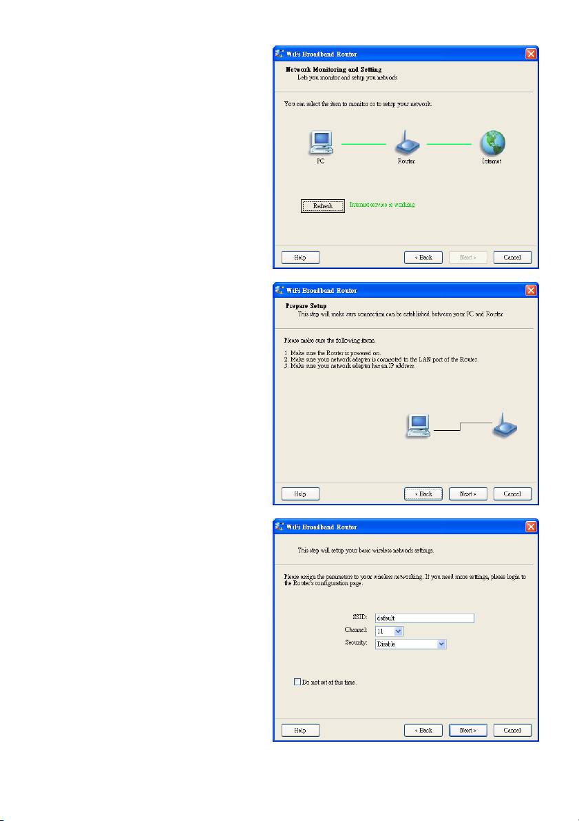
2.3 Advanced Mode Setup.
Check the PC, router or Internet icons for the
status of your PC, router or Internet.
2.4 Quick Wizard Install Mode Setup
1. Check if the router is powered on.
2. Check if your network adapter is connected
to the LAN port of the router.
3. Check if your network adapter has an IP
address.
Click “Next” to continue.
2.5 Wireless Setting
Key in the SSID, Channel and Security
options, and click “Next” to continue.
8
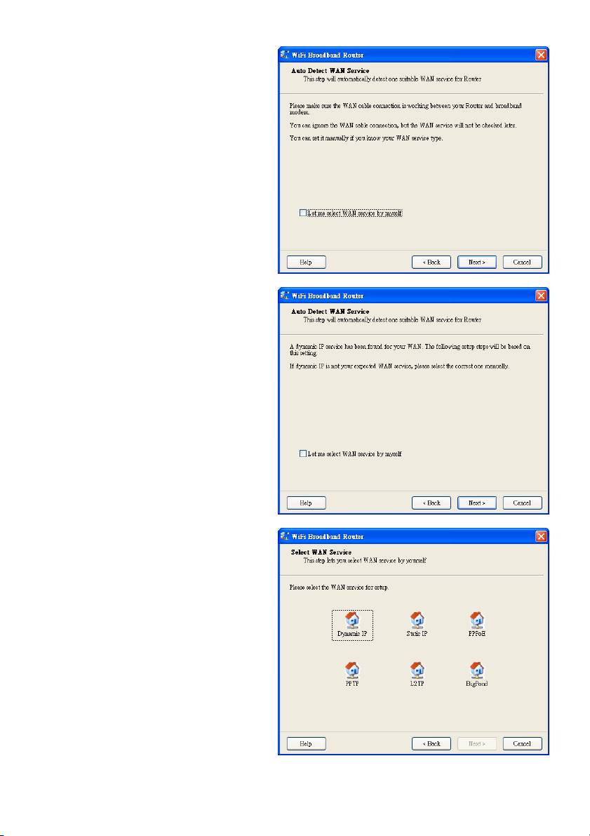
2.6 Auto Detect WAN Service.
Click “Next” to continue.
Disable this function by selecting “Let me
select WAN service by myself”.
Note: This function only supports the
detection of the Dynamic and PPPoE WAN
Services.
For example: the Dynamic WAN type is
detected.
When the detection process is finished, the
router is ready for use.
2.7 Select WAN Service manually.
In manual mode, select an icon and click
“Next” to continue.
9
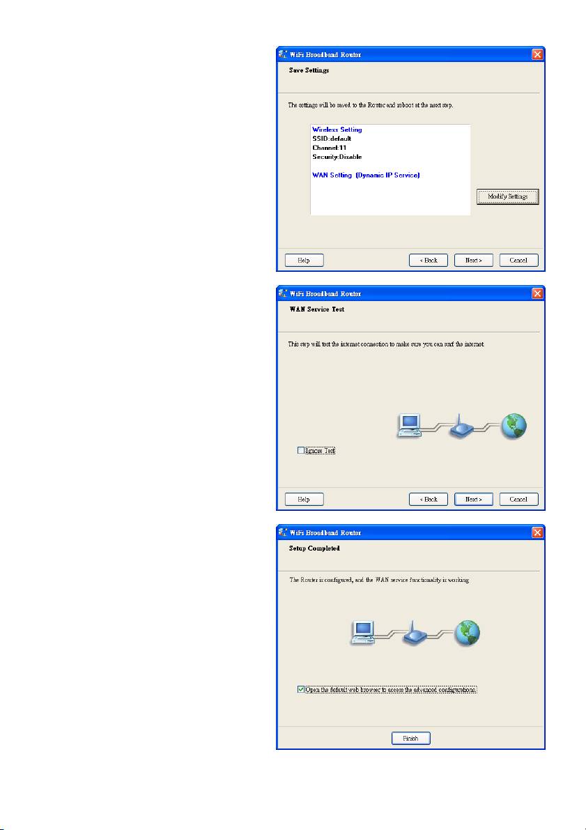
2.8 Apply Settings or Modify.
Click “Next” to apply the settings and continue.
Click “Modify Settings” to change the settings.
2.9 Test the Internet Connection.
Test WAN networking service. Click “Next” to
continue.
You can ignore this step by selecting
“Ignore Test”.
2.10 Setup Completed.
The EzSetup is complete. You can now open
the default web browser to configure the
advanced settings of the router.
Click “Finish” to complete the installation.
10
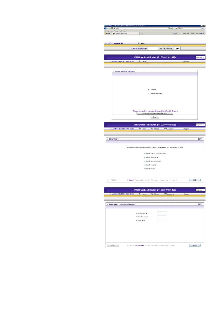
3.) WIZARD CONFIGURATION
Type in the IP Address (http://192.168.0.1)
Insert the and click ‘Login’. The default
password is “admin”.
Select “Wizard” for basic settings, the easiest
way.
Click “Next” to start the wizard.
Step 1:
Set up your system password.
11
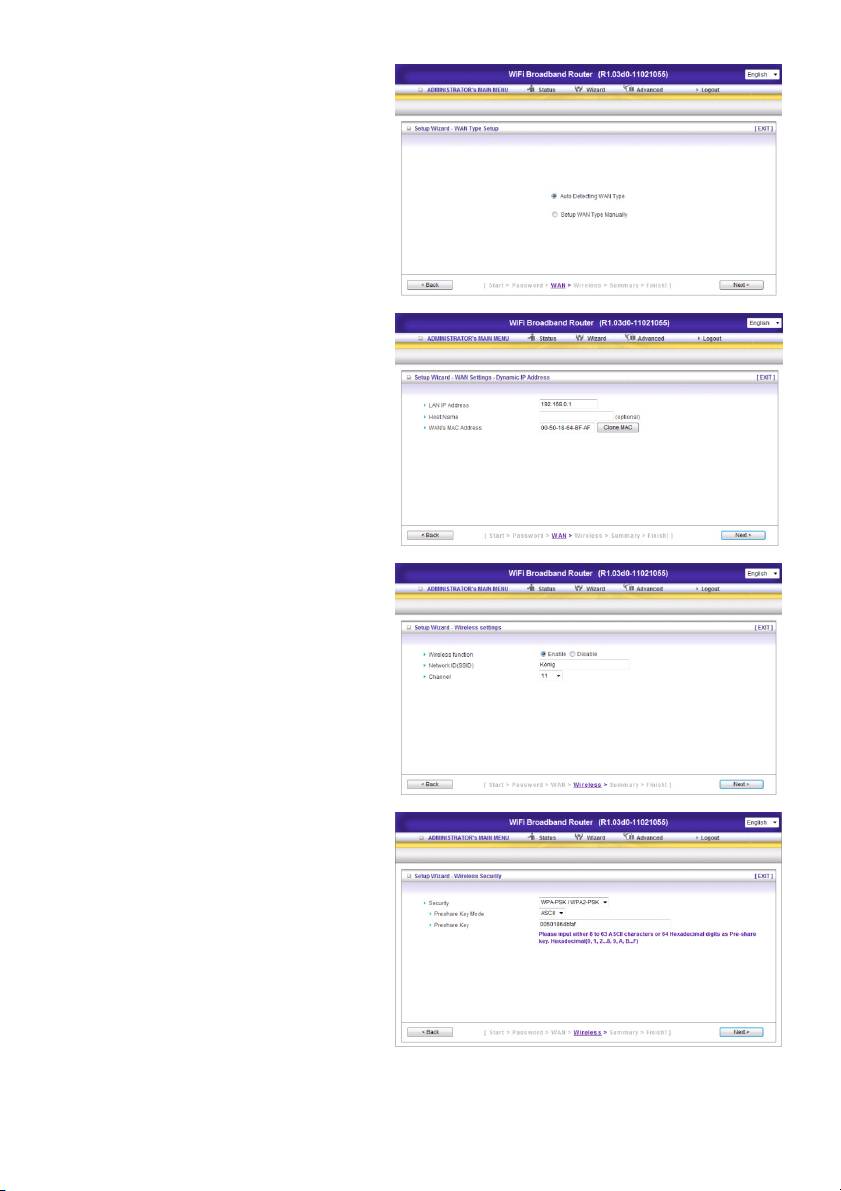
Step 2:
Select “Auto Detecting WAN Type”.
Step 3:
Setup the LAN IP and WAN Type.
Step 4:
Set up your authentication and encryption.
Select WPA-PSK/WPA2-PSK. Now easily fill
in the Preshare key from the bottom of the
router.
12
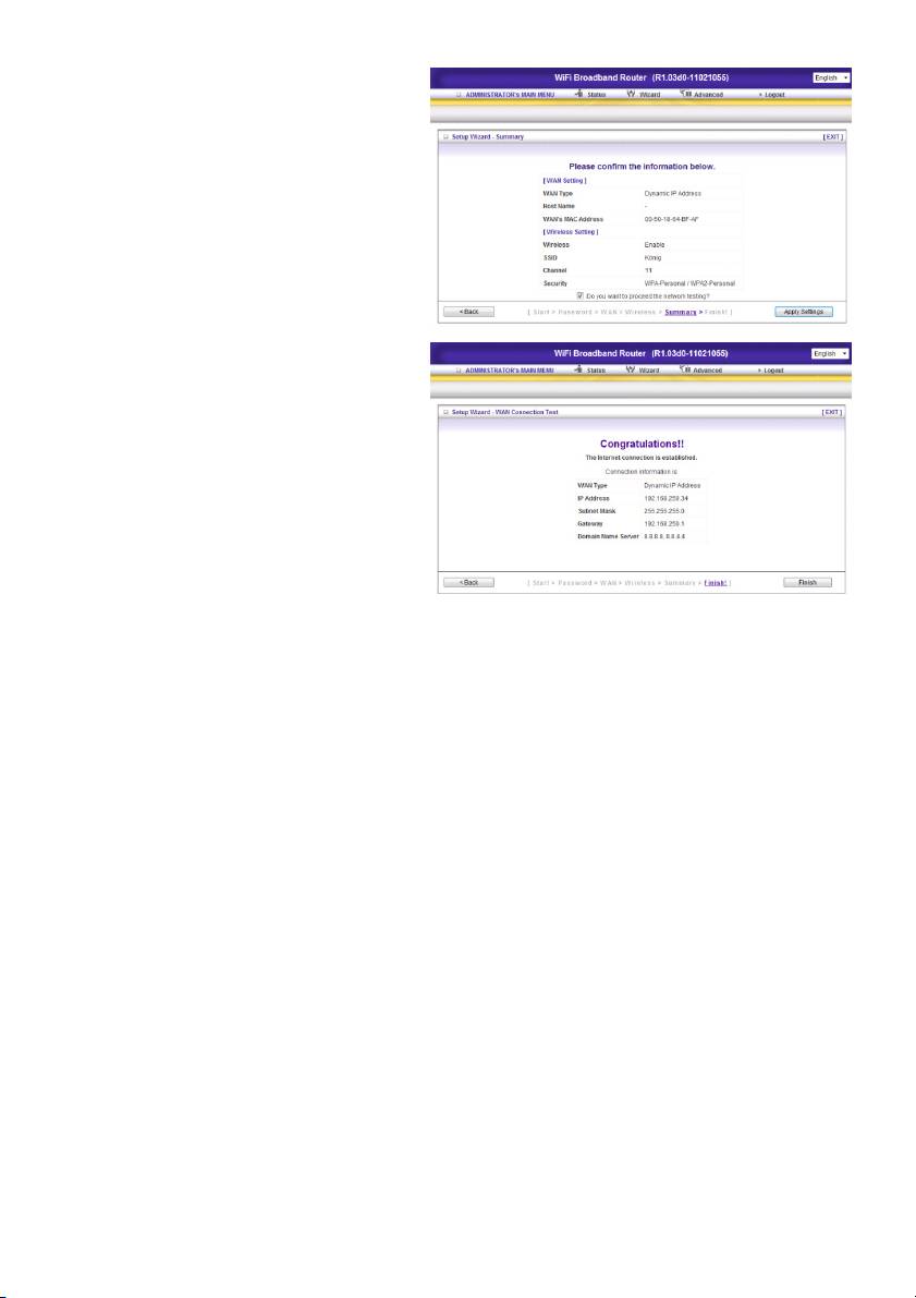
Step 5:
Click “Apply Setting”.
The device will reboot.
Step 6:
Click Finish to complete the wizard. The
Internet connection is established.
13
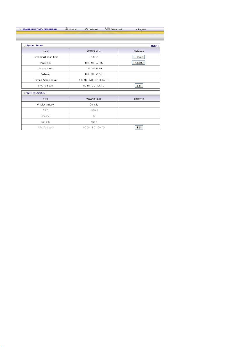
4.) SYSTEM STATUS
This option shows you the product’s working status: WAN status.
If the WAN port is assigned to a dynamic IP, there may appear a “Renew” or “Release” button on the
right side of the column. Click this button to renew or release the IP manually.
Statistics of WAN: enables you to monitor inbound and outbound packets.
14
5.) EXTRA SETTINGS
5.1 Basic settings
Please select “Advanced Setting”.
Click “Change”.
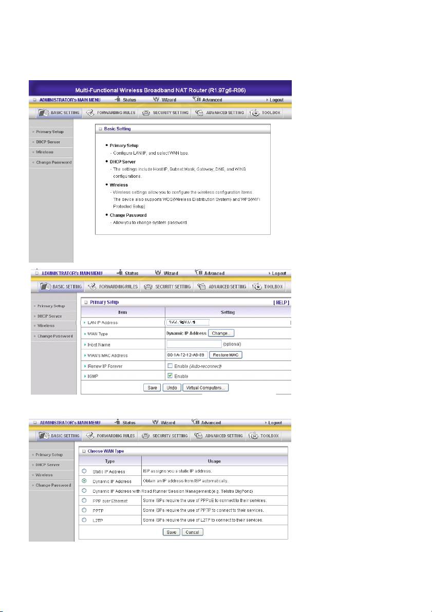
This option is primarily to enable this product to work properly. The setting items and the web
appearance depend on the WAN type. Choose correct WAN type before you start.
15
1. LAN IP Address: the local IP address of this device. The computers on your network must use the
LAN IP address of your product as their Default Gateway. You can change it if necessary.
2. WAN Type: WAN connection type of your ISP. Click the Change button to choose a correct one from
the following options:
A. Static IP Address: ISP assigns you a static IP address.
B. Dynamic IP Address: Obtain an IP address from ISP automatically.
C. PPP over Ethernet: Some ISPs require the use of PPPoE to connect to their services.
D. PPTP: Some ISPs require the use of PPTP to connect to their services.
F. L2TP: Some ISPs require the use of L2TP to connect to their services
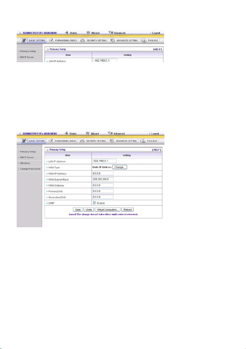
Static IP Address: ISP assigns you a static IP address:
WAN IP Address, Subnet Mask, Gateway, Primary and Secondary DNS: enter the proper settings
provided by your ISP.
16

Dynamic IP Address: Obtain an IP address from ISP automatically.
Host Name: optional. Required by some ISPs, for example @Home.
Renew IP Forever: this feature enables this product to renew your IP address automatically when the
lease time is expiring - even when the system is idle.
PPP over Ethernet: Some ISPs require the use of PPPoE to connect to their services.
PPPoE Account and Password: the account and password your ISP assigned to you. For security
reasons, this field is left blank. If you do not want to change the password, leave the field empty.
PPPoE Service Name: optional. Input the service name if your ISP requires it. Otherwise, leave it blank.
Maximum Idle Time: the amount of time of inactivity before disconnecting your PPPoE session.
Set it to zero or enable Auto-reconnect to disable this feature.
Maximum Transmission Unit (MTU): Most ISPs offer MTU value to users. The most common MTU
value is 1492.
Connection Control: There are 3 modes to select:
Connect-on-Demand: The device will connect to the ISP when the clients send outgoing packets.
Auto-Reconnect (Always-on): The device will connect to the ISP until the connection is established.
Manually: The device will not make the link until someone clicks the Connect button on the Status page.
17
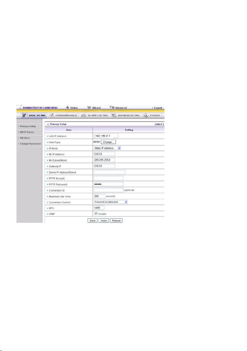
PPTP: Some ISPs require the use of PPTP to connect to their services
First, please check and select the Static IP Address or Dynamic IP Address assigned by your ISP.
1. My IP Address and My Subnet Mask: the private IP address and subnet mask your ISP assigned to
you.
2. Server IP Address: the IP address of the PPTP server.
3. PPTP Account and Password: the account and password your ISP assigned to you. If you do not
want to change the password, keep the field empty.
3. Connection ID: optional. Input the connection ID if your ISP requires it.
4. Maximum Idle Time: the time of no activity to disconnect your PPTP session. Set it to zero or enable
Auto-reconnect to disable this feature. If Auto-Reconnect is enabled and the system has restarted or
the connection has been disconnected, the router will connect to the ISP automatically.
Connection Control: There are 3 modes to select:
Connect-on-demand: The device will connect to the ISP when the clients send outgoing packets.
Auto-Reconnect (Always-on): The device will connect to the ISP until the connection is established.
Manually: The device will not make the link until someone clicks “Connect” on the Status page.
L2TP: Some ISPs require the use of L2TP to connect to their services
First, please check your ISP assigned and select Static IP Address or Dynamic IP Address.
For example: Use Static
1. My IP Address and My Subnet Mask: the private IP address and subnet mask your ISP assigned to
you.
2. Server IP Address: the IP address of the PPTP server.
3. PPTP Account and Password: the account and password your ISP assigned to you. If you do not
want to change the password, leave this field blank.
4. Connection ID: optional. Input the connection ID if your ISP requires it.
5. Maximum Idle Time: the time of no activity to disconnect your PPTP session. Set it to zero or enable
Auto-reconnect to disable this feature. If Auto-Reconnect is enabled and the system has restarted or
the connection has been disconnected, the router will connect to the ISP automatically.
Connection Control: There are 3 modes to select:
Connect-on-demand: The device will link up with ISP when the clients send outgoing packets.
Auto-Reconnect (Always-on): The device will connect to the ISP until the connection is established.
Manually: The device will not connect until someone clicks “Connect” on the Status page.
18
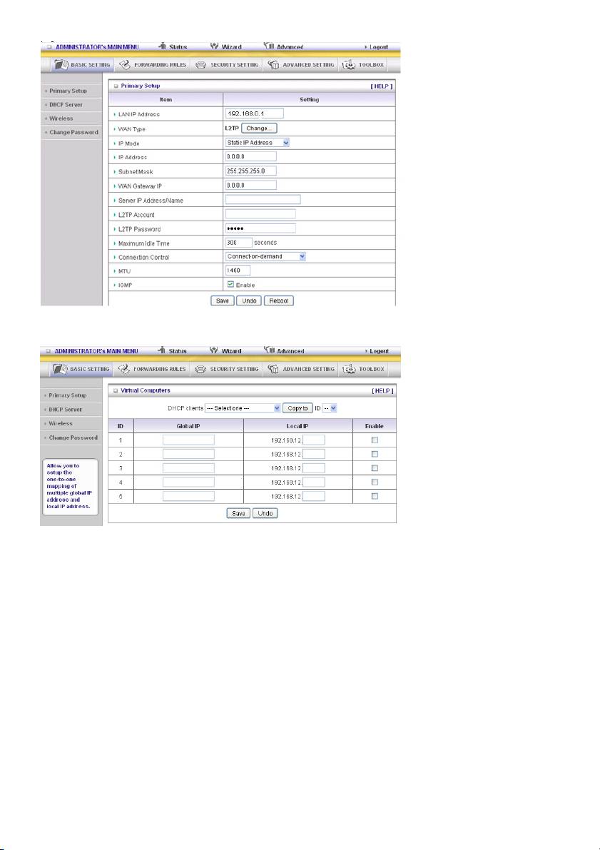
Virtual Computers (only for Static and Dynamic IP address WAN type)
Virtual Computer enables you to use the original NAT feature, and allows you to setup the one-to-one
mapping of multiple global IP address and local IP address.
• Global IP: Enter the global IP address assigned by your ISP.
• Local IP: Enter the local IP address of your LAN PC corresponding to the global IP address.
• Enable: Check this item to enable the Virtual Computer feature.
19
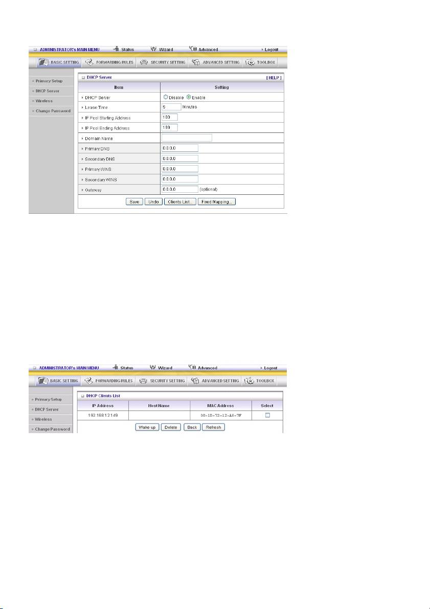
DHCP Server
Press “More>>”
1. DHCP Server: Choose “Disable” or “Enable”.
2. Lease Time: This is the length of time that the client may use the IP address assigned by the DHCP
server.
3. IP Pool Starting Address/IP Pool Starting Address: Whenever there is a request, the DHCP
server will automatically allocate an unused IP address from the IP address pool to the requesting
computer. You must specify the starting and ending address of the IP address pool.
4. Domain Name: Optional, this information will be passed to the client.
5. Primary DNS/Secondary DNS: This feature allows you to assign DNS Servers
6. Primary WINS/Secondary WINS: This feature allows you to assign WINS Servers
7. Gateway: The Gateway Address would be the IP address of an alternate Gateway.
This function enables you to assign another gateway to your PC when the DHCP server offers an IP
to your PC.
8. DHCP Client List:
20
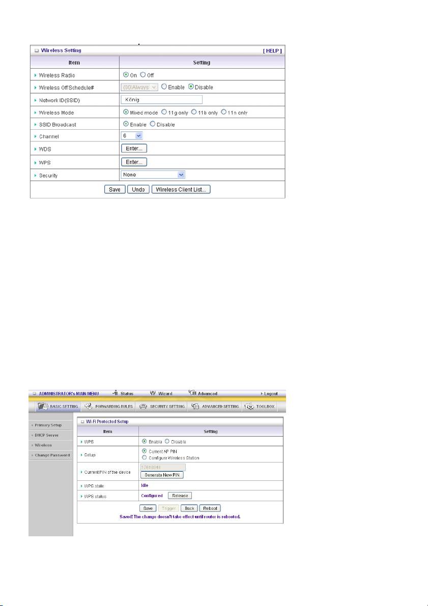
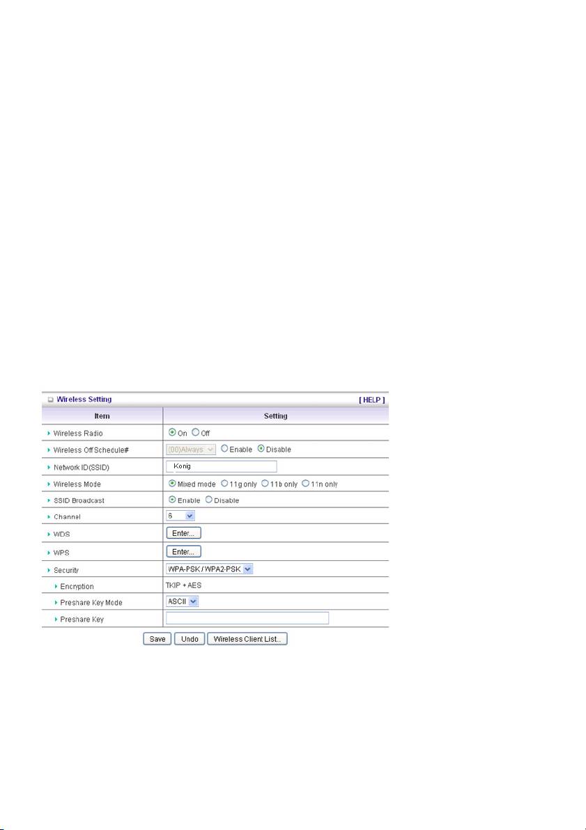
Wireless Setting
Wireless Setting allows you to set the wireless configuration items.
Wireless Radio: The user can turn Wireless Service on or off.
Wireless Off Schedule#: Before switching Wireless Radio off, the device will detect if a wireless
station is online. Then it will, depending on, Schedule “01:00~08:30”, disable the Wi-Fi service.
Network ID (SSID): Network ID is used for identifying the Wireless LAN (Wi-Fi). Client stations can
roam freely over this product and other access points that have the same Network ID. (The factory
setting is “König”)
SSID Broadcast: The router will broadcast beacons that have some information, including SSID so
that the wireless clients know how many AP devices there are by scanning this function in the network.
Therefore, if this function is disabled, the wireless clients cannot find the device from the beacons.
Channel: The radio channel number. The permissible channels depend on the Regulatory Domain.
WPS (Wi-Fi Protection Setup)
WPS is Wi-Fi Protection Setup, which is similar to WCN-NET and offers a safe and easy access in a
wireless connection.
21
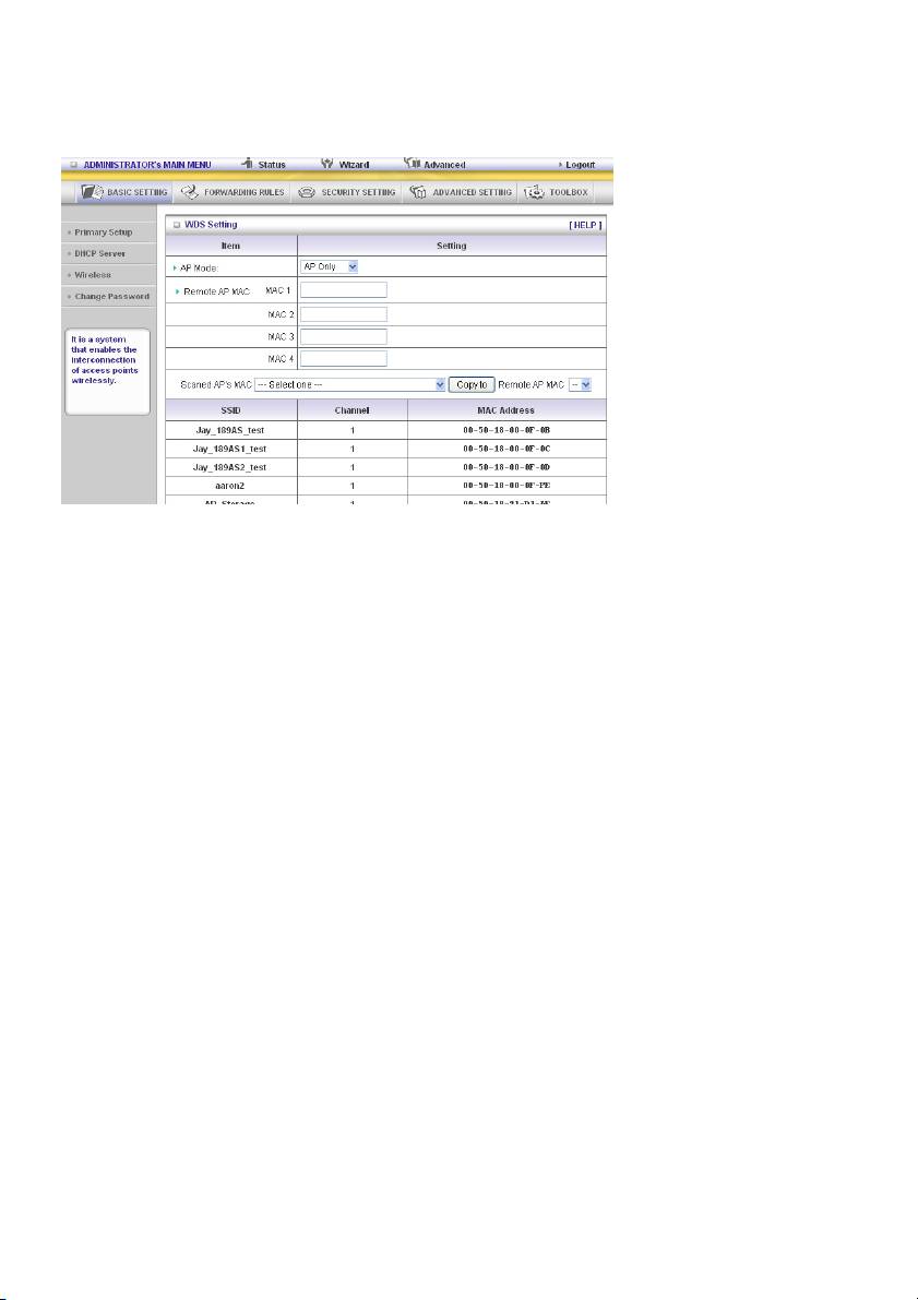
WDS (Wireless Distribution System)
WDS operation as defined by the IEEE802.11 standard has been made available. By using WDS it is
possible to wirelessly connect access points, and in doing so extending a wired infrastructure to
locations where cabling is not possible or inefficient to implement.
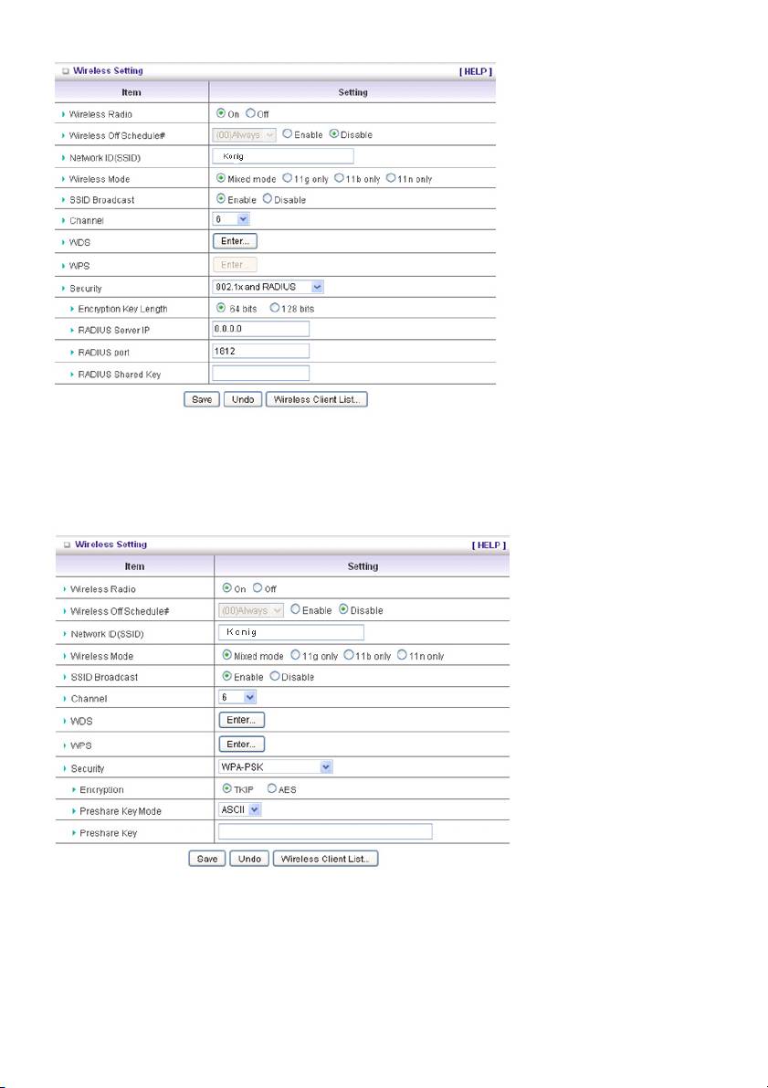
Security: Select the data privacy algorithm you want. Enabling the security can protect your data while
it is being transferred from one station to another.
There are several security types to use:
WEP:
When you enable the 128 or 64 bit WEP key security, please select one WEP key and insert 26 or 10
hexadecimal (0, 1, 2…8, 9, A, B…F) digits.
802.1X
The check box is used to change the function of the 802.1X. When the 802.1X function is enabled, the
wireless user must authenticate to this router first to use the network service.
RADIUS Server
IP address or the 802.1X server’s domain name.
RADIUS Shared Key
Key value is shared by the RADIUS server and this router. This key value is consistent with the key
value in the RADIUS server.
22
A-PSK
1. Select Encryption and Preshare Key Mode
If you select HEX, you have to fill in 64 hexadecimal (0, 1, 2…8, 9, A, B…F) digits. If ASCII is
selected, the length of the preshared key is between 8 and 63 digits.
2. Fill in the key, e.g. 12345678
WPA
The check box is used to change the function of the WPA. When the WPA function is enabled, the
wireless user must authenticate to this router first to use the network service. RADIUS Server IP
address or the 802.1X server’s domain name.
Select Encryption and RADIUS Shared Key
If you select HEX, you have to fill in 64 hexadecimal (0, 1, 2…8, 9, A, B…F) digits.
If ASCII is selected, the length of the preshared key is between 8 and 63.
23
Key value is shared by the RADIUS server and this router. This key value is consistent with the key
value in the RADIUS server.
WPA2-PSK (AES)
1. Select Preshared Key Mode
If you select HEX, you have to fill in 64 hexadecimal (0, 1, 2…8, 9, A, B…F) digits.
If ASCII is selected, the length of the preshared key is between 8 and 63 digits.
2. Fill in the key, e.g. 12345678
WPA2 (AES)
The check box is used to change the function of the WPA. When the WPA function is enabled, the
wireless user must authenticate to this router first to use the network service. RADIUS Server IP
address or the 802.1X server’s domain name.
Select RADIUS Shared Key
If you select HEX, you have to fill in 64 hexadecimal (0, 1, 2…8, 9, A, B…F) digits.
If ASCII is selected, the length of the preshared key is between 8 and 63 digits.
The key value is shared by the RADIUS server and this router. This key value is consistent with the key
value in the RADIUS server.
WPA-PSK /WPA2-PSK
The router will detect automatically which Security type the client uses to encrypt.
1. Select Preshared Key Mode
If you select HEX, you have to fill in 64 hexadecimal (0, 1, 2…8, 9, A, B…F) digits
If ASCII is selected, the length of the preshared key is between 8 and 63.
2. Fill in the key, e.g. 12345678
WPA/WPA2
The check box is used to switch the function of the WPA. When the WPA function is enabled, the
wireless user must authenticate to this router first to use the network service. RADIUS Server The
router will detect automatically which Security type (WPA-PSK version 1 or 2) the client uses to encrypt.
IP address or the 802.1X server’s domain name.
Select RADIUS Shared Key
If you select HEX, you have to fill in 64 hexadecimal (0, 1, 2…8, 9, A, B…F) digits.
If ASCII is selected, the length of preshare key is from 8 to 63.
Key value shared by the RADIUS server and this router. This key value is consistent with the key value
in the RADIUS server.
24
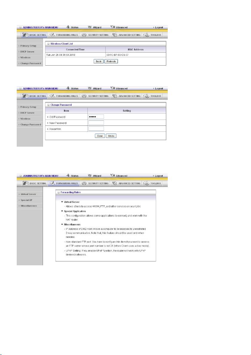
Wireless Client List
Change Password
You can change the password here. We strongly recommend to change the system password for
security reasons.
5.2 Forwarding Rules
25
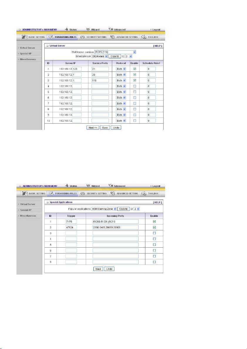
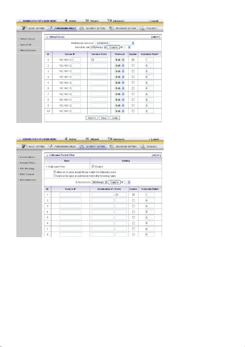
Virtual Server
The NAT firewall of this product filters out unrecognized packets to protect your Intranet, so all hosts
behind this product are invisible to the outside world. If you wish, you can make some of them
accessible by enabling the Virtual Server mapping.
A virtual server is defined as a Service Port, and all requests to this port will be redirected to the
computer specified by the Server IP. The Virtual Server can work with Schedule Rules, and gives the
user more flexibility on access control. For details, please refer to Schedule Rule.
Special AP
Some applications require multiple connections, like Internet games, video conferencing, Internet
telephony, etc. Because of the firewall function, these applications cannot work with a pure NAT router.
The Special Applications feature allows some of these applications to work with this product. If the
mechanism of Special Applications fails to make an application work, try setting your computer as the
DMZ host instead.
1. Trigger: the outbound port number issued by the application.
2. Incoming Ports: when the trigger packet is detected, the inbound packets sent to the specified port
numbers are allowed to pass through the firewall.
26
This product provides some predefined settings. Select your application and click Copy to add the
predefined setting to your list.
Note! Only one PC can use a Special Application tunnel.
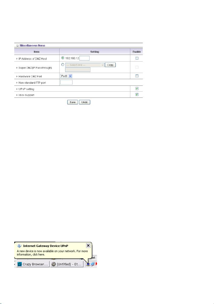
Miscellaneous Items
IP Address of DMZ Host
DMZ (Demilitarized Zone) Host is a host without the protection of firewall. It allows a computer to
participate in an unrestricted 2-way communication for Internet games, video conferencing, Internet
telephony and other special applications.
NOTE: This feature should be used only when needed.
Super DMZ (IP Passthrough)
The client must be set in Super DMZ and the DHCP server assigns a global IP which is the same with
WAN IP of this device. This client also can access the local client. This client behind NAT can use
various applications without limitation.
Hardware DMZ Port
This feature can let the device get Global IP from ISP directly. Some devices, such as an STB or an
MOD, should work via the assigned port.
Non-standard FTP port
You have to configure this item if you want to access an FTP server whose port number is not 21. This
setting will be lost after rebooting.
Xbox Support
The Xbox is a video game console produced by Microsoft Corporation. Please enable this function
when you play games.
UPnP Setting
The device also supports this function. If the OS supports this function enable it, like Windows XP.
When the user receives an IP from the device anicon as below will be displayed:
27
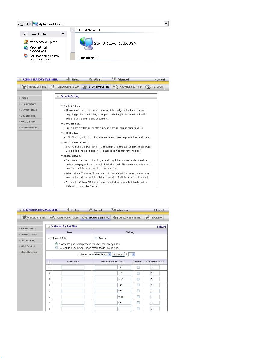
5.3 SECURITY SETTING
Packet Filters
28
Packet Filter enables you to control what packets are allowed to pass the router. Outbound filter applies
on all outbound packets. However, inbound filter applies on packets that are destined to virtual servers
or DMZ host only. You can select one of the two filtering policies:
1. Allow all to pass except those that match the specified rules
2. Deny all to pass except those that match the specified rules
You can specify 8 rules for each direction: inbound or outbound. For each rule, you can define the
following:
• Source IP address
• Source port address
• Destination IP address
• Destination port address
• Protocol: TCP or UDP or both.
• Use Rule#
For source or destination IP address, you can define a single IP address (4.3.2.1) or a range of IP
addresses (4.3.2.1-4.3.2.254). If no prefix has been added, all port addresses will apply.
For source or destination port, you can define a single port (80) or a range of ports (1000-1999). Add
prefix "T" or "U" to specify TCP or UDP protocol. For example, T80, U53, U2000-2999. No prefix
indicates both TCP and UDP are defined. An empty implies all port addresses. Packet Filter can work
with Schedule Rules, and give user more flexibility on access control. For details, please refer to
Schedule Rule.
Each rule can be enabled or disabled individually.
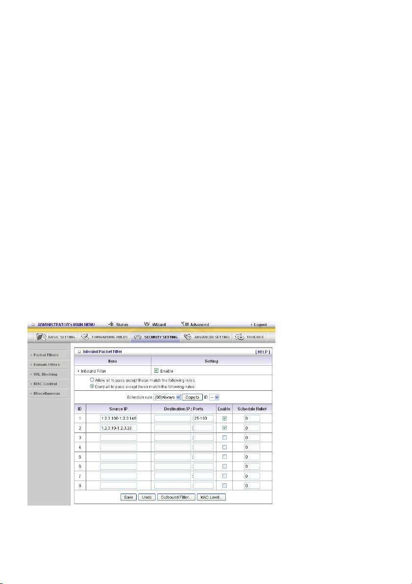
Inbound Filter:
To enable Inbound Packet Filter click the check box next to Enable in the Inbound Packet Filter
field.
Suppose you have SMTP Server (25), POP Server (110), Web Server (80), FTP Server (21), and News
Server (119) defined in Virtual Server or DMZ Host.
Example 1:
(1.2.3.100-1.2.3.149) Remote hosts are allowed to send mail (port 25), and browse the Internet
(port 80)
(1.2.3.10-1.2.3.20) Remote hosts can do everything (block nothing)
Others are all blocked.
29
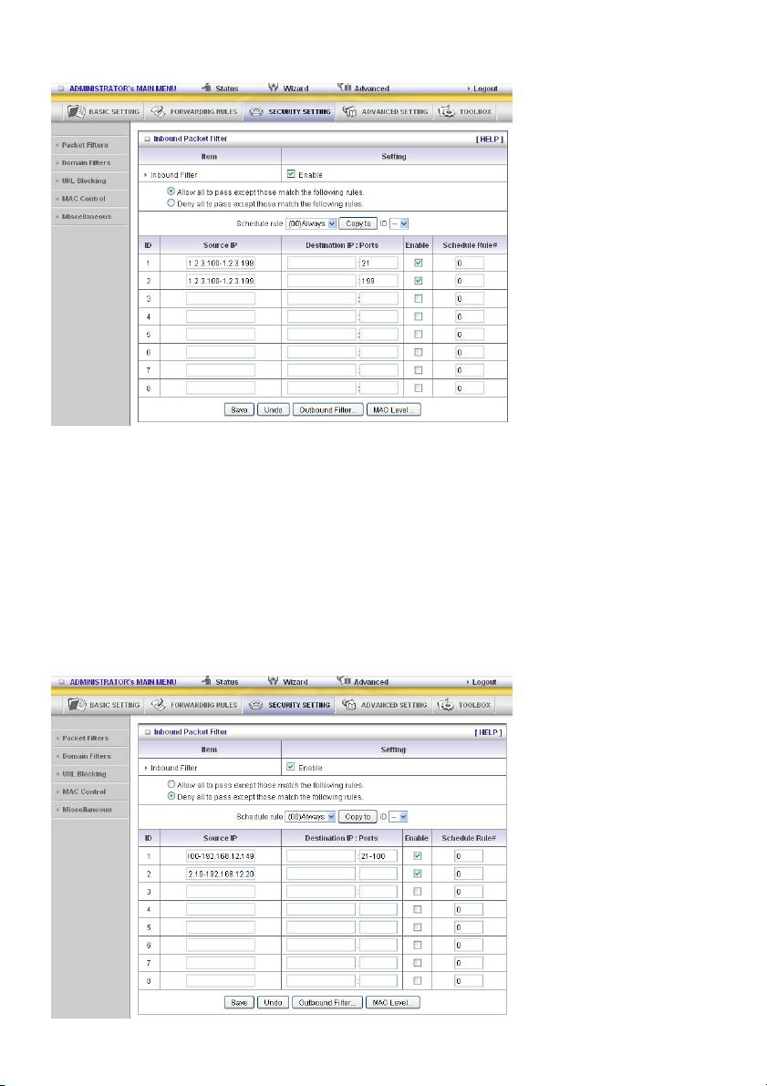
Example 2:
(1.2.3.100-1.2.3.119) Remote hosts can do everything except read net news (port 119) and transfer
files via FTP (port 21) behind router server.
Others are all allowed.
After Inbound Packet Filter setting is configured, click the Save button.
Outbound Filter:
To enable Outbound Packet Filter click the check box next to Enable in the Outbound Packet Filter
field.
Example 1:
Router LAN IP is 192.168.12.254
30
(192.168.12.100-192.168.12.149) Located hosts are only allowed to send e-mail (port 25), receive
e-mail (port 110), and browse the Internet (port 80); port 53 (DNS) is necessary to resolve the domain
name.
(192.168.12.10-192.168.12.20) Located hosts can do everything (block nothing)
Others are all blocked.
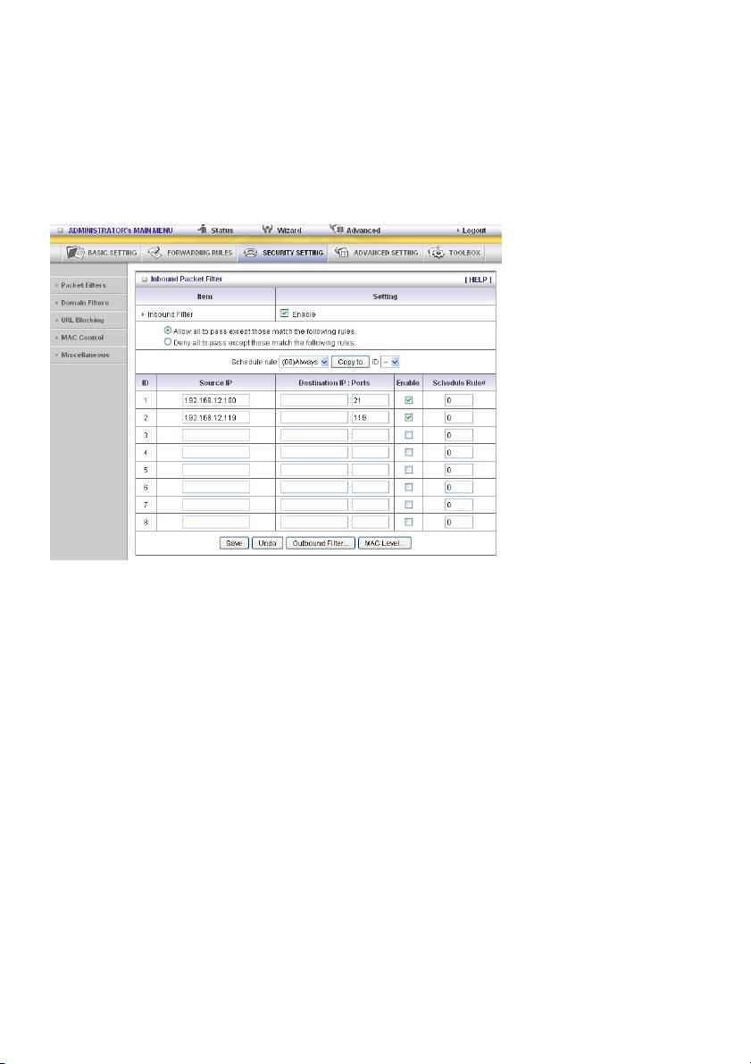
Example 2:
Router LAN IP is 192.168.0.1
(192.168.12.100 and 192.168.12.119) Located hosts can do everything except read net news (port 119)
and transfer files via FTP (port 21)
Others are allowed
After Outbound Packet Filter setting is configured, click the Save button.
31
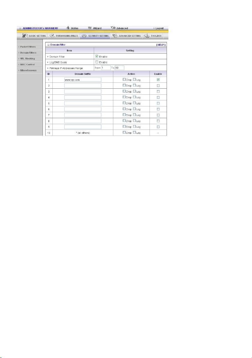
Domain Filters
Domain Filter
Lets you prevent users under this device from accessing specific URLs.
Domain Filter Enable
Check if you want to enable Domain Filter.
Log DNS Query
Check if you want to log the action when someone accesses the specific URLs.
Privilege IP Addresses Range
Setting a group of hosts and privilege these hosts to access network without restriction.
Domain Suffix
A suffix of URL to be restricted. For example, “.com”, “xxx.com”.
Action
What kind of action do you want when someone is accessing the URL with the domain suffix?
Check Drop to block the access. Check Log to log the access.
Enable
Check to enable each rule.
32
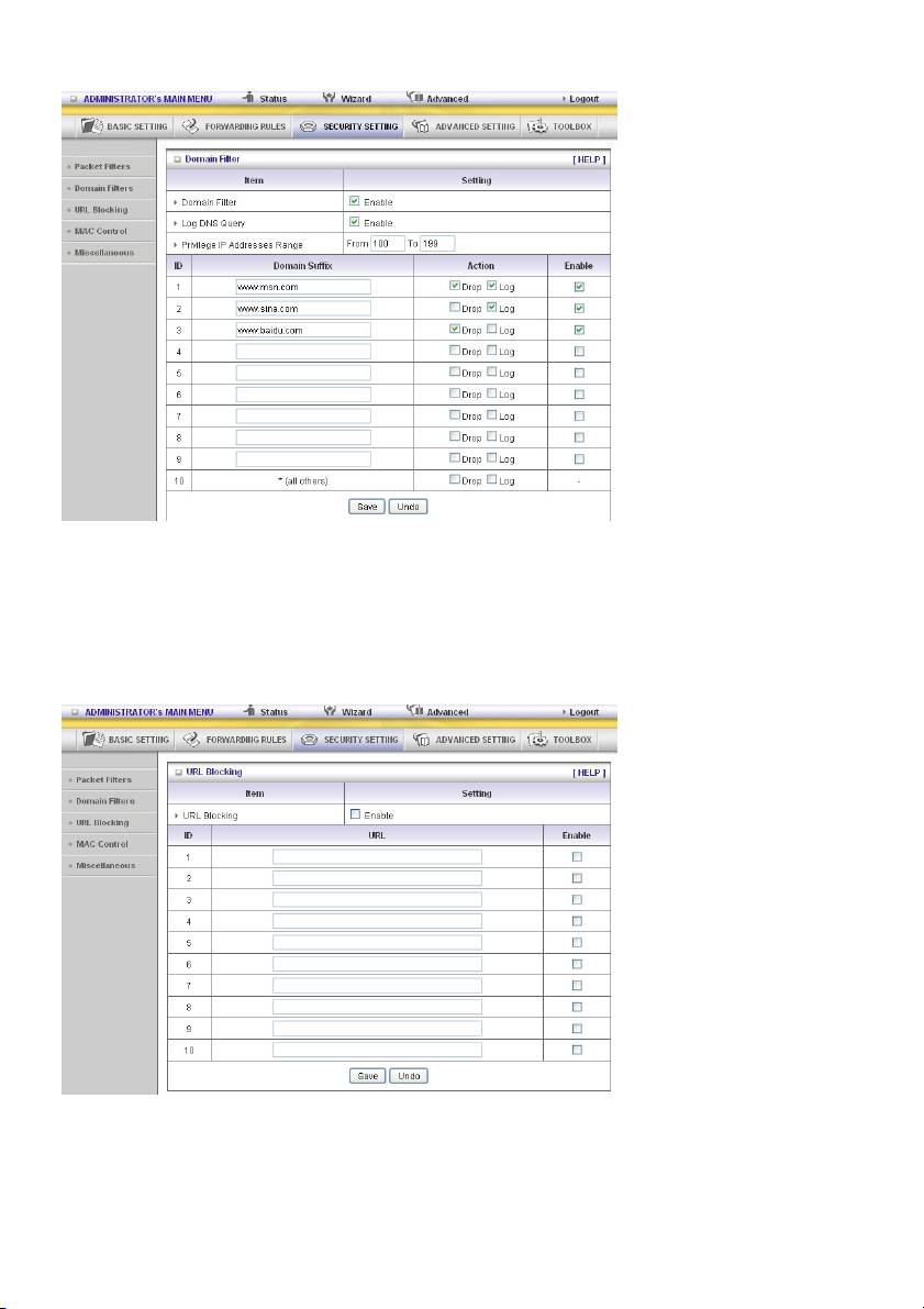
Example:
In this example:
1. The URL, including “www.msn.com”, will be blocked, and the action will be recorded on log file.
2. The URL, including “www.sina.com”, will not be blocked, but the action will be recorded on log file.
3. The URL, including “www.baidu.com”, will be blocked, but the action will not be recorded on log file.
4. IP address x.x.x.1~x.x.x.99 can access Internet without restriction.
URL Blocking
URL Blocking will block LAN computers to connect to pre-defined Websites.
The major difference between “Domain Filter” and “URL Blocking” is that Domain Filter requires the
user to input suffix (like .com or .org, etc.), while URL Blocking requires the user to input a keyword only.
In other words, Domain Filter can block specific websites, while URL Blocking can block hundreds of
websites by simply a keyword.
33
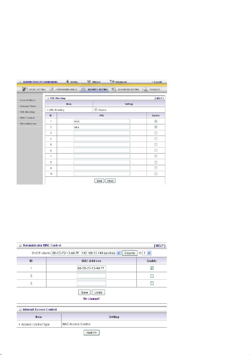
URL Blocking Enable
Check if you want to enable URL Blocking.
URL
If any part of the Website's URL matches the pre-defined word, the connection will be blocked.
For example, you can use pre-defined word “sex” to block all websites if their URLs contain pre-defined
word “sex”.
Enable
Check to enable each rule.
In this example:
1. URL including “msn” will be blocked, and the action will be recorded on log file.
2. URL including “sina” will be blocked, but the action will be recorded on log file
MAC Control
Administrator MAC Control
Regardless of the MAC access configuration of the administrator, a specific MAC address can access
the device.
34
This device can record 3 sets. When the host (must be admin) logs in to the web management, the
device will record MAC address of this host. Before this host configures the Internet Access Control, we
suggest the end-user to enable this feature first.
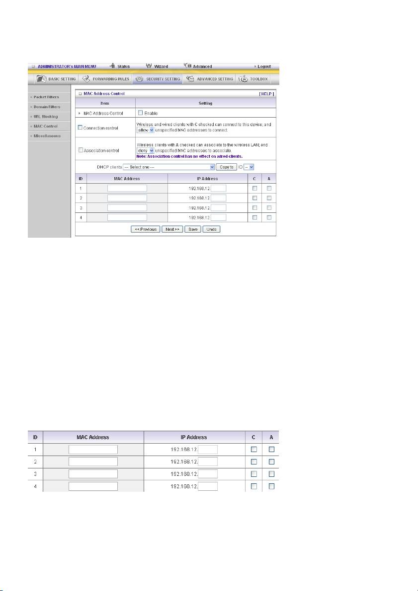
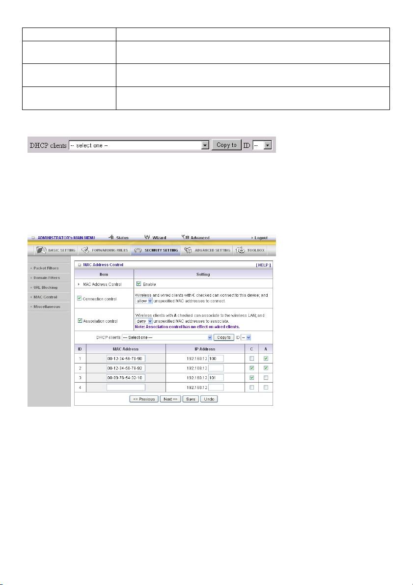
MAC Address Control allows you to assign different access rights for different users and to assign a
specific IP address to a certain MAC address.
MAC Address Control Check “Enable” to enable the “MAC Address Control”. All of the settings
in this page will take effect only when “Enable” is checked.
Connection control Check “Connection control” to enable the controlling of which wired and
wireless clients can connect to this device. If a client is denied to connect
to this device, it means the client cannot access the Internet either.
Choose “allow” or “deny” to allow or deny the clients, whose MAC
addresses are not in the “control table” (please see below), to connect to
this device.
Association control Check “Association control” to enable the controlling of which wireless
client can associate to the wireless LAN. If a client is denied to associate
to the wireless LAN, it means the client cannot send or receive any data
via this device. Choose “allow” or “deny” to allow or deny the clients,
whose MAC addresses are not in the “control table”, to associate to the
wireless LAN.
Control table
“Control table” is the table at the bottom of the “MAC Address Control” page. Each row of this table
indicates the MAC address and the expected IP address mapping of a client. There are four columns in
this table:
35
MAC Address The MAC address indicates a specific client.
IP Address Expected IP address of the corresponding client. Leave it blank if you are
not interested in the IP address.
C When “Connection control” is selected, select “C” to allow the
corresponding client to connect to this device.
A When “Association control” is selected, select “A” to allow the
corresponding client to associate to the wireless LAN.
In this page, we provide the following combo box and button to help you to input the MAC address.
You can select a specific client in the “DHCP clients” combo box, and then click on the “Copy to” button
to copy the MAC address of the client you select to the ID selected in the “ID” combo box.
Previous page and Next
To make this setup page simple and clear, we have divided the “control
Page
table” into several pages. You can use these buttons to navigate to
different pages.
Example:
In this scenario, there are three clients listed in the control table. Clients 1 and 2 are wireless, and client
3 is wired.
1. The “MAC Address Control” function is enabled.
2. “Connection control” is enabled, and all of the wired and wireless clients not listed in the “control
table” are “allowed” to connect to this device.
3. “Association control” is enabled, and all of the wireless clients not listed in the “control table” are
“denied” to associate to the wireless LAN.
4. Clients 1 and 3 have fixed IP addresses either from the DHCP server of this device or are manually
assigned:
ID 1 – “00-12-34-56-78-90” --> 192.168.12.100
ID 3 – “00-98-76-54-32-10” --> 192.168.12.101
Client 2 will obtain its IP address from the IP address pool specified in the "DHCP Server" page or it
can use a manually assigned static IP address.
36
If, for example, client 3 tries to use an IP address different from the address listed in the control table
(192.168.12.101), it will be denied to connect to this device.
5. Clients 2 and 3 and other wired clients with a MAC address unspecified in the control table are all
allowed to connect to this device. But client 1 is denied to connect to this device.
6. Clients 1 and 2 are allowed to associate to the wireless LAN, but a wireless client with a MAC
address not specified in the control table is denied to associate to the wireless LAN. Client 3 is a
wired client and so is not affected by Association control.
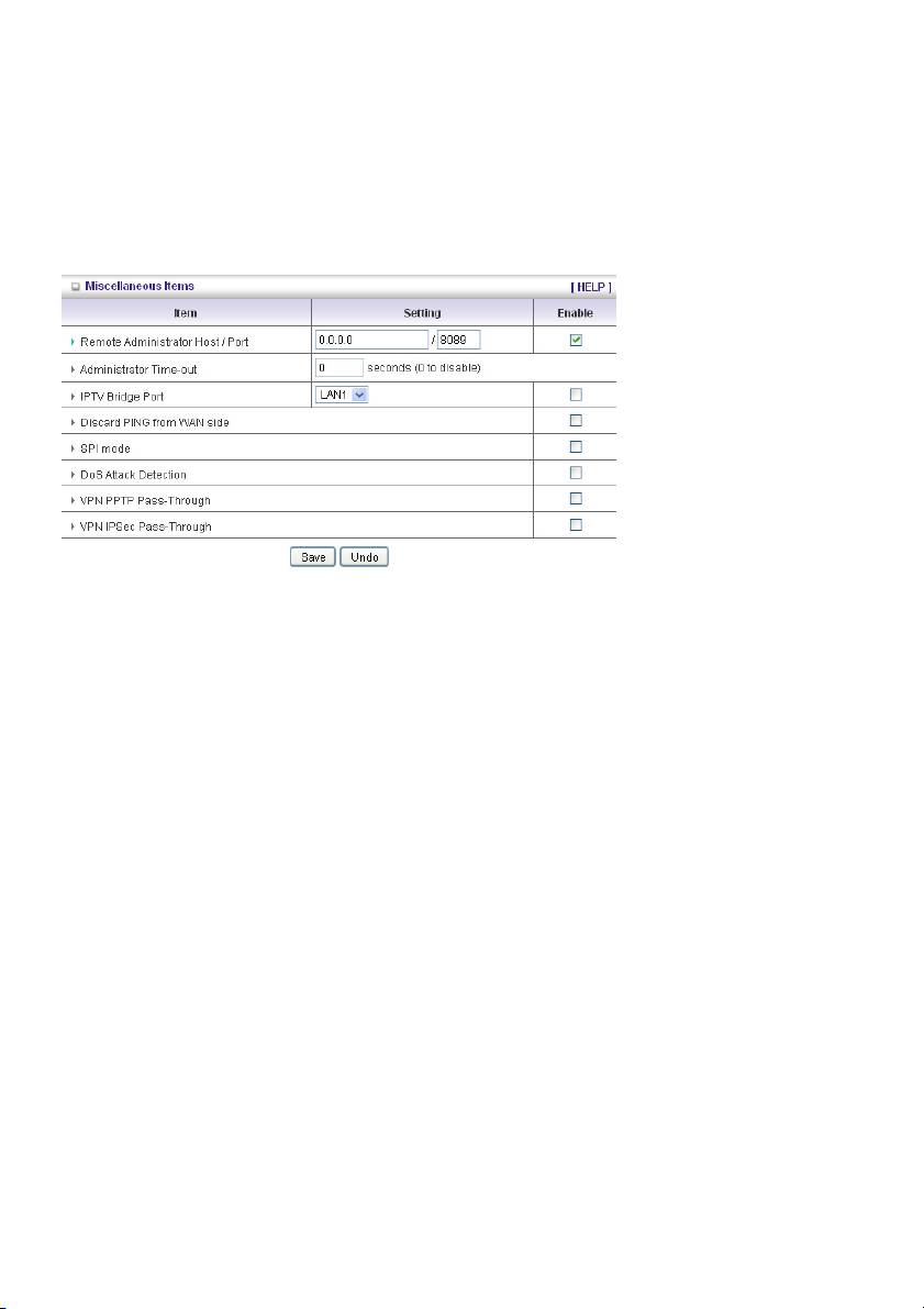
Miscellaneous Items
Remote Administrator Host/Port
In general, only Intranet users can browse the built-in web pages to perform administration tasks. This
feature enables you to perform administration tasks from a remote host. If this feature is enabled, only
the specified IP address can perform remote administration. If the specified IP address is 0.0.0.0, any
host can connect to this product to perform administration tasks. You can use subnet mask bits “/nn”
notation to specify a group of trusted IP addresses. For example, “10.1.2.0/24”.
NOTE: When Remote Administration is enabled, the web server port will be shifted to 88. You can
change the web server port to another port, too.
Administrator Time-out
The time of no activity to logout automatically. Set it to zero to disable this feature.
Discard PING from WAN side
When this feature is enabled, any host on the WAN cannot ping this product.
SPI Mode
When this feature is enabled, the router will record the packet information that passes through the
router such as an IP address, port address, ACK, SEQ number and so on. And the router will check
every incoming packet to detect if this packet is valid.
DoS Attack Detection
When this feature is enabled, the router will detect and log the DoS attack from the Internet. Currently,
the router can detect the following DoS attack: SYN Attack, WinNuke, Port Scan, Ping of Death, Land
Attack etc.
VPN PPTP and IPSec Pass-Through
Virtual Private Networking (VPN) is typically used for work-related networking. For VPN tunnels, the
router supports IPSec Pass-through and PPTP Pass-through.
37
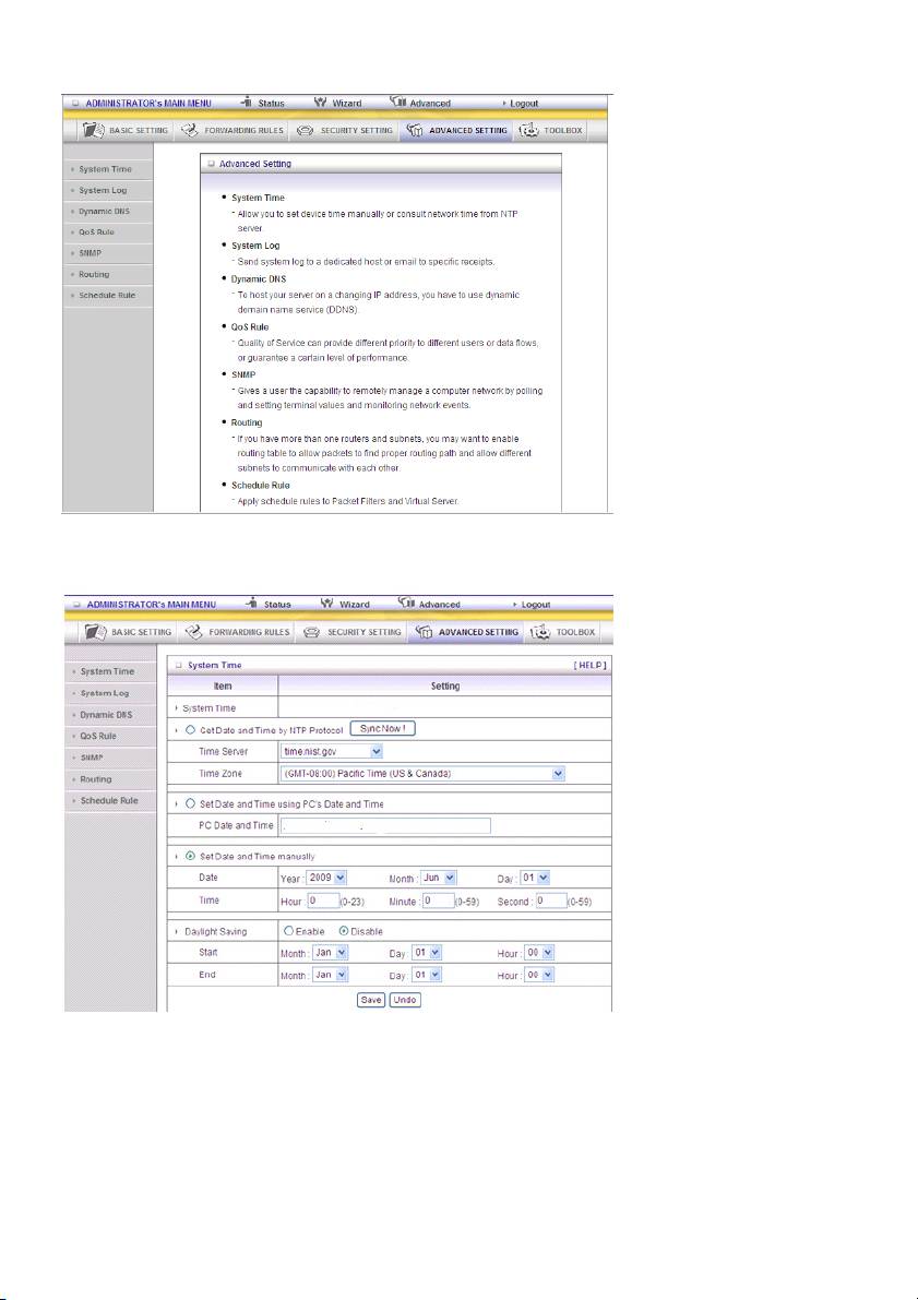
5.4 ADVANCED SETTING
System Time
Get Date and Time by NTP Protocol
Selected if you want to get date and time by NTP protocol.
Time Server
Select an NTP time server to consult UTC time.
Time Zone
Select the time zone where this device is located.
38
Set Date and Time manually
Selected if you want to set date and time manually.
Function of Buttons
Sync Now: Synchronize system time with network time server
Daylight Saving: Set up where the location is.
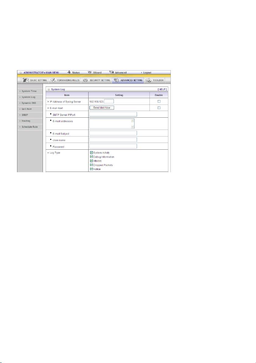
System Log
This page supports two methods to export system logs to specific destinations: syslog (UDP) and
SMTP (TCP). The items you have to setup include:
IP Address for Syslog
Host IP of destination where syslogs will be sent to.
Check Enable to enable this function.
E-mail Alert Enable
Check if you want to enable email alert (send syslog via email).
SMTP Server IP and Port
Input the SMTP server IP and port, which are connected with ‘:’. If you do not specify the port number,
the default value is 25.
For example, “mail.your_url.com” or “192.168.1.100:26”.
Send E-mail alert to
The recipients who will receive these logs. You can assign more than 1 recipient, using ‘;’ or ‘,’ to
separate these email addresses.
39
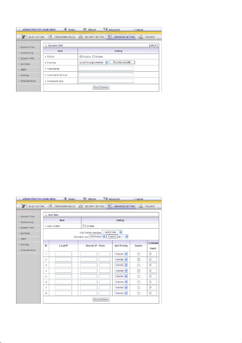
Dynamic DNS
To host your server on a changing IP address, you have to use the dynamic domain name service
(DDNS).
So that anyone wishing to reach your host only needs to know the name of it. Dynamic DNS will map
the name of your host to your current IP address, which changes each time you connect to your
Internet service provider.
Before you enable Dynamic DNS, you need to register an account on one of these Dynamic DNS
servers that we list in provider field.
To enable Dynamic DNS click the check box next to Enable in the DDNS field.
Next enter the appropriate information about your Dynamic DNS server.
You have to define:
Provider
Host Name
Username/E-mail
Password/Key
You will get this information when you register an account on a Dynamic DNS server.
QoS
This device supports the QoS function. The user could set up a specified upstream connection with
different priorities. There are three priorities to be selected. The packets with high priority will be
processed first.
40
1. QoS: Quality of Service.
2. Local IP/Ports: The IP and ports that LAN side PC uses. The value 0 is not used.
3. Remote IP : Ports: The IP and ports that remote server uses. The value 0 is not used.
For example, if you want to guarantee the HTTP bandwidth, you could keep Local IP/Port as 0/0 and
Remote IP/Port as 0/80.
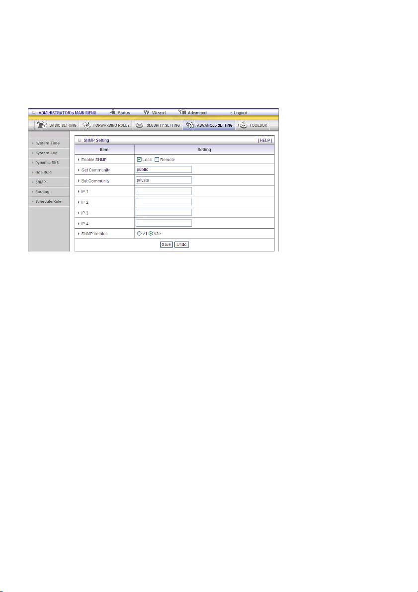
SNMP
In brief, SNMP, the Simple Network Management Protocol, is a protocol designed to give a user the
capability to remotely manage a computer network by polling and setting terminal values and
monitoring network events.
Enable SNMP
You must check Local or Remote or both to enable SNMP function. If Local is checked, this device will
respond to requests from LAN. If Remote is checked, this device will respond to requests from WAN.
Get Community
Setting the community of Get Request that your device will respond to.
Set Community
Setting the community of Set Request your device will accept.
IP 1, IP 2, IP 3, IP 4
Input your SNMP Management PC’s IP here. The user has to configure this device so it knows where to
send the SNMP trap message.
SNMP Version
Please select the correct SNMP version that your SNMP management software supports.
WAN Access IP Address
If the user wants to limit access to specific IP address , please input the item. The default is 0.0.0.0 and
means every IP of the Internet can get some information of the device with SNMP protocol.
Click on “Save” to store your setting or “Undo” to cancel.
41
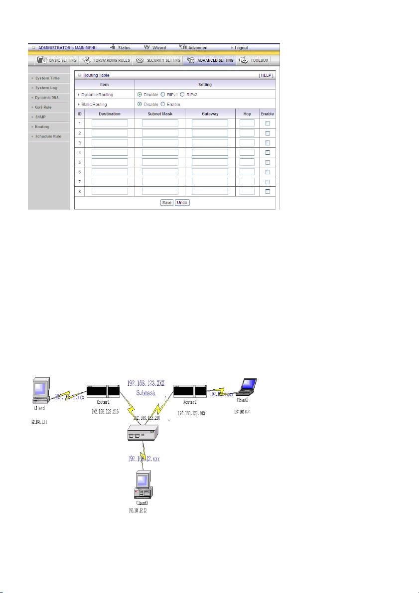
Routing
Routing Table allows you to determine which physical interface address to use for outgoing IP data
grams. If you have more than one router and subnet, you will need to enable the routing table to allow
packets to find the proper routing path and allow different subnets to communicate with each other.
Routing table settings are settings used to set up the functions of static routing.
Dynamic Routing
Routing Information Protocol (RIP) will exchange information about destinations for computing routes
throughout the network. Please select RIPv2 only if you have different subnets in your network.
Otherwise, please select RIPv1 if you need this protocol.
Static Routing: For static routing, you can specify up to 8 routing rules. You can enter the destination
IP Address, Subnet Mask, Gateway, Hop for each routing rule, and then enable or disable the rule by
checking or unchecking the Enable check box.
Example:
42
Configuration on NAT Router
Destination Subnet Mask Gateway Hop Enabled
192.168.0.1 255.255.255.0 192.168.123.216 1 ˇ
192.168.0.0 255.255.255.0 192.168.123.103 1 ˇ
So if, for example, the client 3 wanted to send an IP data gram to 192.168.0.2, it would use the above
table to determine that it had to go via 192.168.123.103 (a gateway),
And if it sends packets to 192.168.1.11 it will go via 192.168.123.216
Each rule can be enabled or disabled individually.
After Routing Table setting is configured, click the Save button.
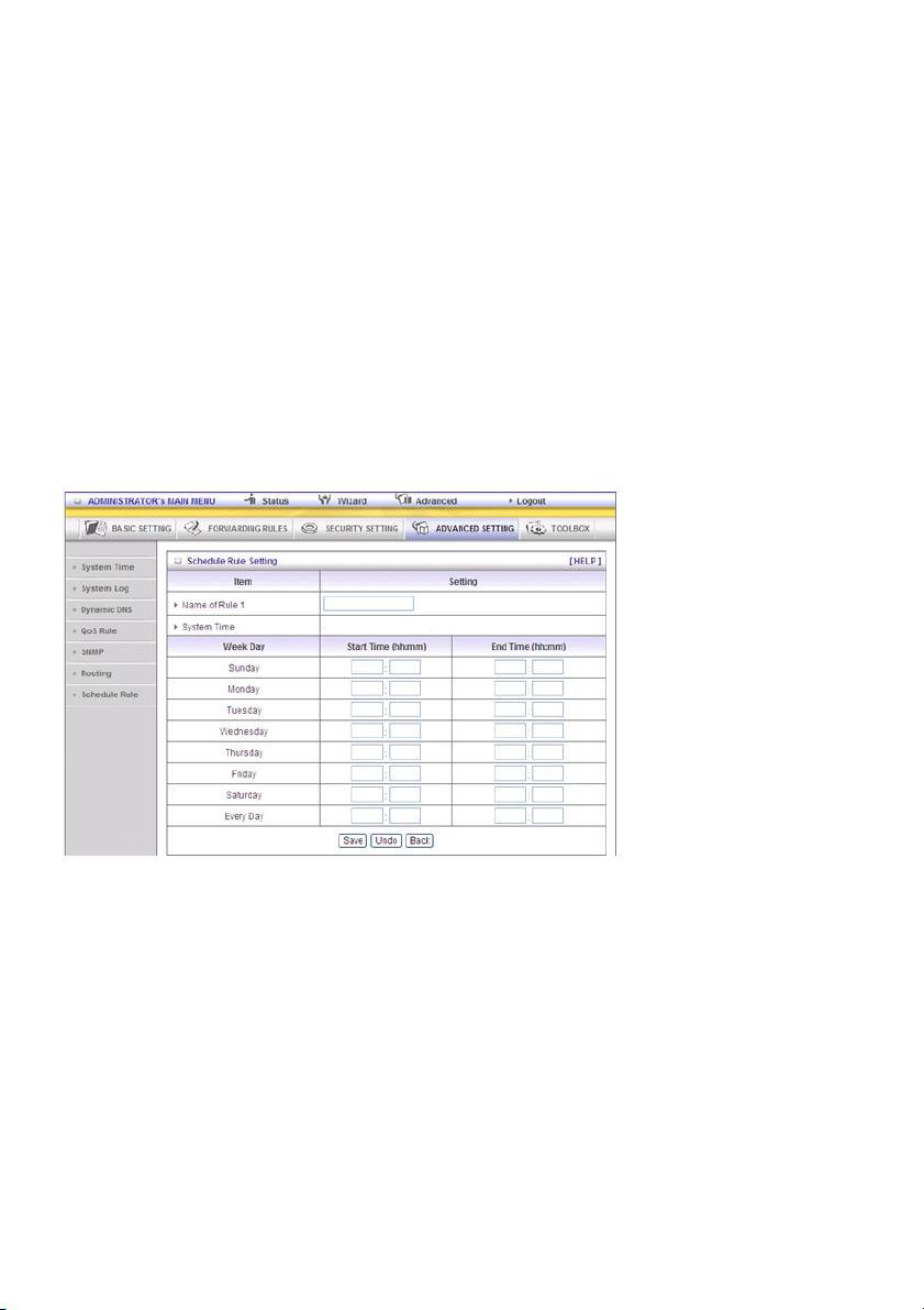
Schedule Rule
You can set the schedule time to decide which service will be turned on or off. Select the “enable” item.
Press “Add New Rule”
You can write a rule name and set which day and what time should be scheduled by filling in the fields
“Start Time” and “End Time”.The following example configures “ftp time” as everyday 14:10 to 16:20
Schedule Enable
Select if you want to enable the scheduler.
Edit
To edit the schedule rule.
Delete
To delete the schedule rule and the rule # of the rules behind the deleted one will decrease by one
automatically.
Schedule rule can be applied to virtual server and packet filter, for example:
Example 1: Virtual Server – Apply Rule#1 (ftp time: everyday 14:20 to 16:30)
43
Example 2: Packet Filter – Apply Rule#1 (ftp time: everyday 14:20 to 16:30).
44
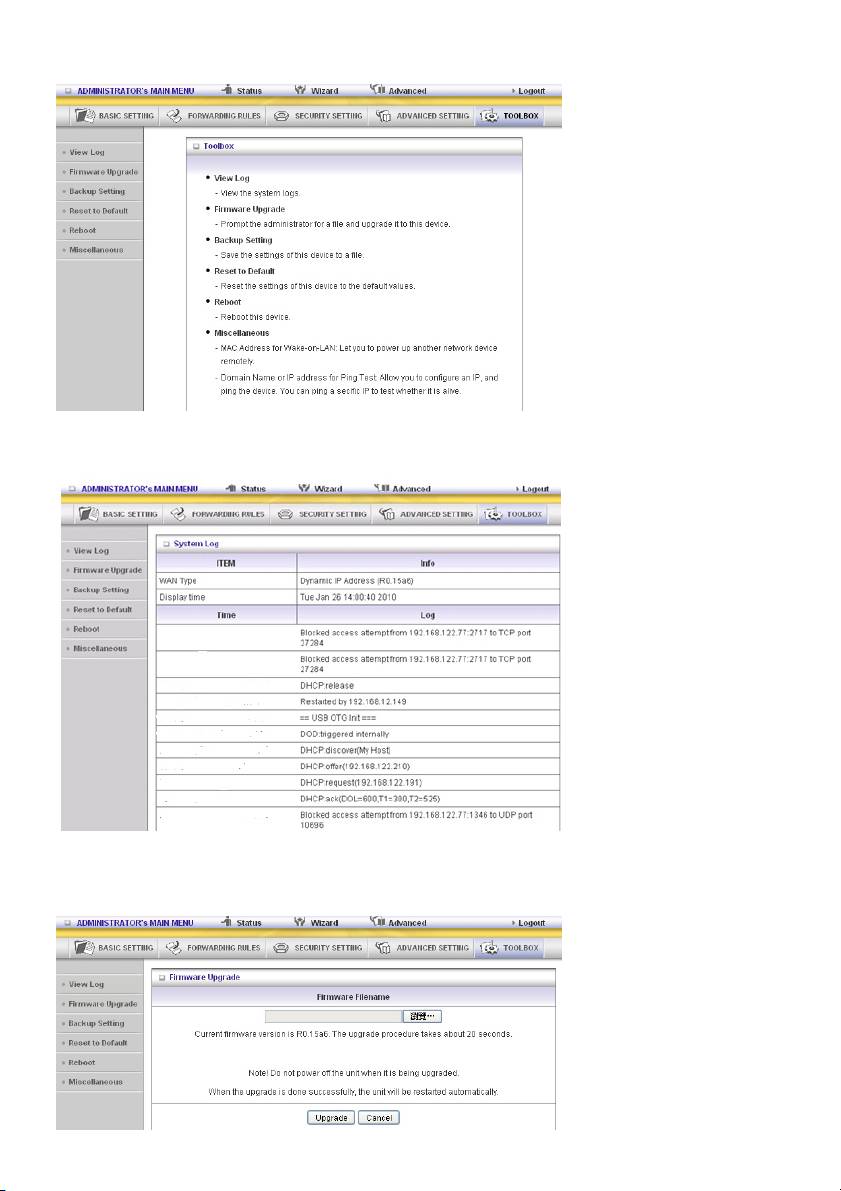
5.5 TOOLBOX
View Log
You can view the system log by clicking the View Log button
Firmware Upgrade
45
You can upgrade the firmware by clicking the Firmware Upgrade button.
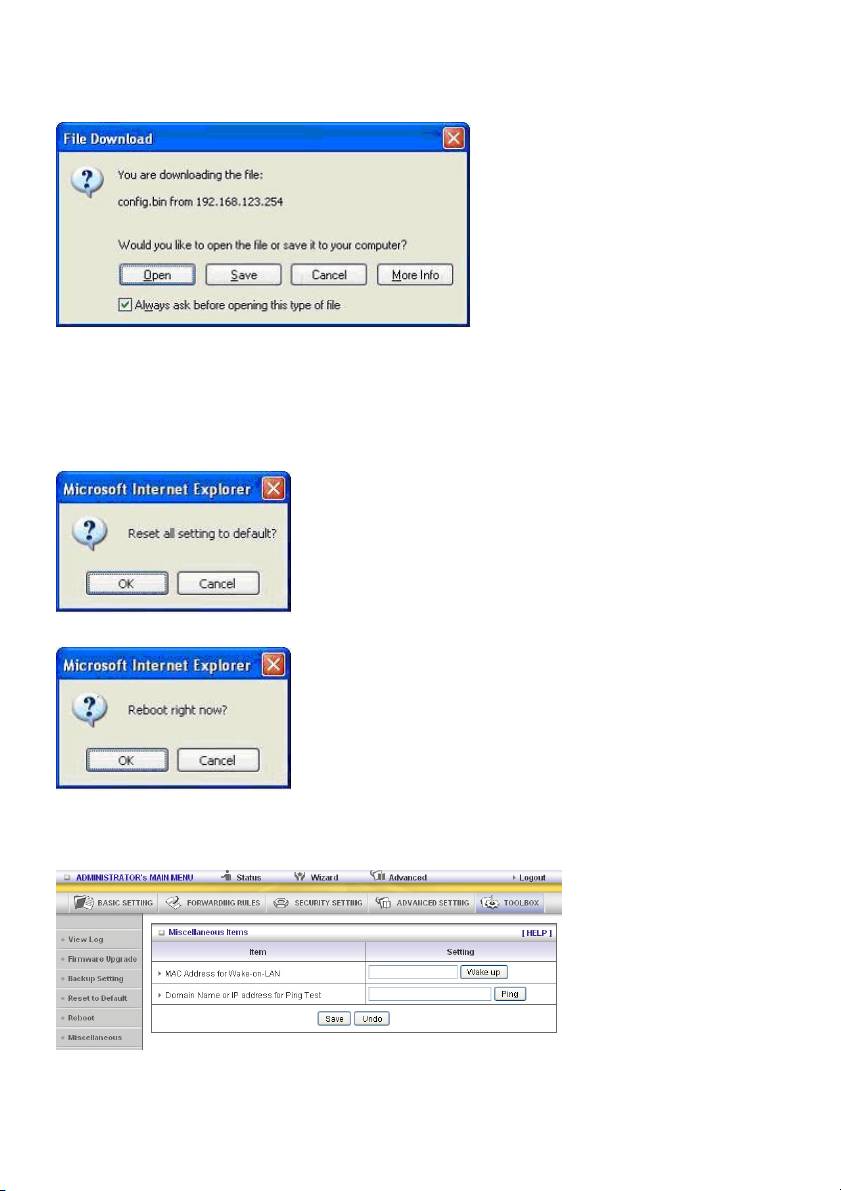
5.6 Backup Setting
You can backup your settings by clicking the Backup Setting button and save it as a bin file. Once you
want to restore these settings, please click the Firmware Upgrade button and use the bin file you
saved.
Reset to default
You can also reset this product to factory default by clicking the Reset to default button.
You can also reboot this product by clicking the Reboot button.
Miscellaneous Items
MAC Address for Wake-on-LAN
Wake-on-LAN is a technology that enables you to power up a networked device from a distance. In
order to enjoy this feature, the target device must be Wake-on-LAN-enabled and you have to know the
46

MAC address of this device, say 00-11-22-33-44-55. Click “Wake up” so that the router will send the
wake-up frame to the target device immediately.
Domain Name or IP Address for Test
Allows you to configure an IP, and ping the device. You can ping a specific IP to test whether it is alive.
Safety precautions:
To reduce risk of electric shock, this product should ONLY be
opened by an authorised technician when service is required.
Disconnect the product from mains and other equipment if a
problem should occur. Do not expose the product to water or
moisture.
Maintenance:
Clean only with a dry cloth. Do not use cleaning solvents or abrasives.
Warranty:
No guarantee or liability can be accepted for any changes and modifications of the product or damage
caused due to incorrect use of this product.
General:
- Designs and specifications are subject to change without notice.
- All logos, brands or brand logos and product names are trademarks or registered trademarks of their
respective holders and are hereby recognised as such.
- This manual was produced with care. However, no rights can be derived. König Electronic can not
accept liability for any errors in this manual or their consequences.
- Keep this manual and packaging for future reference.
Attention:
This product is marked with this symbol. It means that used electrical and electronic products
should not be mixed with general household waste. There is a separate collections system for
these products.
47
