Hach-Lange POLYMETRON 9523 Basic User Manual: Operation
Operation: Hach-Lange POLYMETRON 9523 Basic User Manual
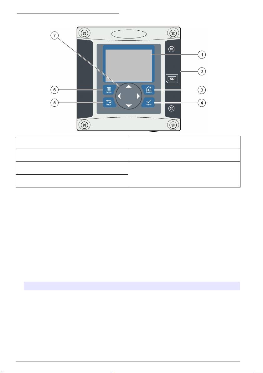
Figure 6 Keypad and front panel overview
1 Instrument display 5 BACK key. Moves back one level in the menu
structure.
2 Cover for secure digital memory card slot 6 MENU key. Moves to the Settings Menu from other
screens and submenus.
3 HOME key. Moves to the Main Measurement
7 Directional keys. Used to navigate through the
screen from other screens and submenus.
menus, change settings, and increment or
decrement digits.
4 ENTER key. Accepts input values, updates, or
displayed menu options.
Inputs and outputs are set up and configured through the front panel using the keypad and display
screen. This user interface is used to set up and configure inputs and outputs, create log information
and calculated values, and calibrate sensors. The SD interface can be used to save logs and update
software.
Operation
Contacting conductivity sensor configuration
Use the CONFIGURE menu to enter identification information for the sensor and to change options
for data handling and storage.
1. Push the menu key and select SENSOR SETUP>[Select Sensor]>CONFIGURE.
2. Select an option and push enter. To enter numbers, characters or punctuation, push and hold the
up or down arrow keys. Push the right arrow key to advance to the next space.
Option Description
EDIT NAME Changes the name that corresponds to the sensor on the top of the measure screen.
The name is limited to 16 characters in any combination of letters, numbers, spaces or
punctuation. Only the first 12 characters are displayed on the controller.
SENSOR S/N Allows the user to enter the serial number of the sensor, limited to 16 characters in any
combination of letters, numbers, spaces or punctuation.
SELECT MEASURE Changes the measured parameter to CONDUCTIVITY (default), TDS (total dissolved
solids), SALINITY or RESISTIVITY. All other configured settings are reset to the
default values.
Note: If SALINITY is selected, the measurement unit is defined as ppt (parts per
thousand) and cannot be changed.
18 English

Option Description
DISPLAY FORMAT Changes the number of decimal places that are shown on the measure screen. When
set to auto, the number of decimal places changes automatically with changes in the
measured value.
MEAS UNITS Changes the units for the selected measurement—select the unit from the list
available.
TEMP UNITS Sets the temperature units to °C (default) or °F.
T-COMPENSATION Adds a temperature-dependent correction to the measured value:
• NONE—Temperature compensation not required
• USP—Set the alarm level for the standard USP definition table
• ULTRA PURE WATER—Not available for TDS. Set the compensation type
according to the sample characteristics—Select NaCl , HCl, AMMONIA or ULTRA
PURE WATER
• USER—Select BUILT IN LINEAR, LINEAR or TEMP TABLE:
• BUILT IN LINEAR—Use the pre-defined linear table (slope defined as 2.0%/°C,
reference temperature as 25 °C)
• LINEAR—Set the slope and reference temperature parameters if different from
the built-in parameters
• TEMP TABLE—Set the temperature and multiplication factor points (refer to the
conductivity module documentation)
• NATURAL WATER—Not available for TDS
CONFIG TDS TDS only—changes the factor that is used to convert conductivity to TDS: NaCl
(0.49 ppm/µS) or CUSTOM (enter factor between 0.01 and 99.99 ppm/µS).
CABLE PARAM Sets the sensor cable parameters to improve measurement accuracy when the sensor
cable is extended or shortened from the standard 5 m. Enter the cable length,
resistance and capacitance.
TEMP ELEMENT Sets the temperature element to PT100 or PT1000 for automatic temperature
compensation. If no element is used, the type can be set to MANUAL and a value for
temperature compensation can be entered.
FILTER Sets a time constant to increase signal stability. The time constant calculates the
average value during a specified time—0 (no effect) to 60 seconds (average of signal
value for 60 seconds). The filter increases the time for the sensor signal to respond to
actual changes in the process.
LOG SETUP Sets the time interval for data storage in the data log—5, 30 seconds, 1, 2, 5, 10,
15 (default), 30, 60 minutes.
RESET DEFAULTS Sets the configuration menu to the default settings. All sensor information is lost.
Resin option
Use the RESIN option to view and change the parameters related to the resin cartridge. These
parameters must be defined before the analyzer is used for the first time.
1. Push the menu key and select TEST/MAINT>RESIN.
2. To monitor the status of the resin select the TRACK option and push enter.
Option Description
YES Monitor the resin status. When the life expectancy of the resin is less than 10 days a warning
message is triggered. When the life expectancy reaches 0 days a system error is triggered.
NO The resin is not monitored.
English 19

3. To view the current status of the resin select the STATUS option and push enter. The date the
resin was last changed and the current life expectancy are displayed. Push back to return to the
menu or enter to reset the parameters.
4. To reset the resin parameters select PARAMETERS and push enter. Based on the values input,
the life expectancy of the resin is recalculated.
Option Description
CAPACITY Use the arrow keys to enter the resin exchange capacity (0.5 to 5.0 mole/liter).
VOLUME Use the arrow keys to enter the volume of resin (0.5 to 20 liters).
FLOW Use the arrow keys to enter the sample flow rate through the cartridge (2 to
20 liters/hour).
CONCENTRATION Use the arrow keys to enter the resin concentration (0 to 20 ppm).
Calibration
About sensor calibration
The sensor characteristics slowly shift over time and cause the sensor to lose accuracy. The sensor
must be calibrated regularly to maintain accuracy. The calibration frequency varies with the
application and is best determined by experience.
Use air (zero calibration) and the process sample to define the calibration curve. When the process
sample is used, the reference value must be determined with a secondary verification instrument.
Cell constant
Before making a calibration make sure the sensor cell parameters are correct.
1. Push the menu key and select SENSOR SETUP>[Select Sensor]>CALIBRATE.
2. If the pass code is enabled in the security menu for the controller, enter the pass code.
3. Select CELL CONSTANT and push enter.
4. Contacting conductivity sensors: Select the cell K range for the sensor (0.01, 0.1 or 1.0) then
enter the actual K value as printed on the label attached to the sensor.
Inductive conductivity sensors: Enter the actual K value as printed on the label attached to the
sensor.
Temperature calibration
It is recommended to calibrate the temperature sensor once a year. Calibrate the temperature sensor
before calibrating the measurement sensor.
1. Measure the temperature of the water with an accurate thermometer or independent instrument.
2. Push the menu key and select SENSOR SETUP>CALIBRATE.
3. If the pass code is enabled in the security menu for the controller, enter the pass code.
4. Select 1 PT TEMP CAL and push enter.
5. The raw temperature value is displayed. Push enter.
6. Enter the correct value if different from that displayed and push enter.
7. Push enter to confirm the calibration. The temperature offset is displayed.
Zero calibration procedure
Use the zero calibration procedure to define the unique zero point of the sensor.
1. Remove the sensor from the process. Wipe with a clean towel to make sure the sensor is dry.
2. Push the menu key and select SENSOR SETUP>[Select Sensor]>CALIBRATE.
3. If the pass code is enabled in the security menu for the controller, enter the pass code.
4. Select ZERO CAL and push enter.
20
English

5. Select the option for the output signal during calibration:
Option Description
ACTIVE The instrument sends the current measured output value during the calibration procedure.
HOLD The sensor output value is held at the current measured value during the calibration procedure.
TRANSFER A preset output value is sent during calibration. Refer to the controller user manual to change
the preset value.
6. Place the sensor in air, push enter.
7. Review the calibration result:
• PASS—the sensor is calibrated and ready to measure samples.
• FAIL—the calibration is outside of accepted limits. Clean the sensor and retry. Refer to
Troubleshooting on page 24 for more information.
8. If the calibration passed, push enter to continue.
9. If the option for operator ID is set to YES in the CAL OPTIONS menu, enter an operator ID. Refer
to Change calibration options on page 22.
10. On the NEW SENSOR screen, select whether the sensor is new:
Option Description
YES The sensor was not calibrated previously with this controller. The days of operation and previous
calibration curves for the sensor are reset.
NO The sensor was calibrated previously with this controller.
11. Return the sensor to the process and push enter. The output signal returns to the active state
and the measured sample value is shown on the measure screen.
Note: If the output mode is set to hold or transfer, select the delay time when the outputs return to the active
state.
Calibration with the process sample
The sensor can remain in the process sample.
1. Push the menu key and select SENSOR SETUP>CALIBRATE.
2. If the pass code is enabled in the security menu for the controller, enter the pass code.
3. Select SAMPLE CAL and push enter.
4. Select the option for the output signal during calibration:
Option Description
ACTIVE The instrument sends the current measured output value during the calibration procedure.
HOLD The sensor output value is held at the current measured value during the calibration procedure.
TRANSFER A preset output value is sent during calibration. Refer to the controller user manual to change
the preset value.
5. With the sensor in the process sample, push enter. The measured value is shown. Wait for the
value to stabilize and push enter.
6. With a certified secondary verification instrument measure the concentration value of the sample.
To avoid impurities in the sample take the measurement before the sample enters the flow
chamber. Use the arrow keys to enter this value if different from the value displayed and push
enter.
7. Review the calibration result:
• PASS—the sensor is calibrated and the calibration factor is displayed.
• FAIL—the calibration is outside of accepted limits. Clean the sensor and retry. Refer to
Troubleshooting on page 24 for more information.
English
21
Оглавление
- English..............................................................................................................................3 Deutsch..........................................................................................................................25 Italiano............................................................................................................................48 Français.........................................................................................................................71 Español..........................................................................................................................94 Português....................................................................................................................118 中文...............................................................................................................................141 Nederlands.................................................................................................................160 Polski............................................................................................................................184 Suomi............................................................................................................................207 Русский........................................................................................................................229
- Table of contents
- General information
- Installation
- Analyzer startup
- Operation
- Maintenance
- Troubleshooting
- Inhaltsverzeichnis
- Allgemeine Informationen
- Installation
- Analysator starten
- Benutzeroberfläche und Navigation
- Wartung
- Fehlerbehebung
- Sommario
- Informazioni generali
- Installazione
- Avvio dell'analizzatore
- Interfaccia utente e navigazione
- Manutenzione
- Risoluzione dei problemi
- Table des matières
- Généralités
- Installation
- Mise en marche de l'analyseur
- Interface utilisateur et navigation
- Entretien
- Recherche de panne
- Tabla de contenidos
- Información general
- Instalación
- Inicio del analizador
- Interfaz del usuario y navegación
- Mantenimiento
- Solución de problemas
- Índice
- Informação geral
- Instalação
- Arranque do analisador
- Interface do utilizador e navegação
- Manutenção
- Resolução de problemas
- 目录
- 基本信息
- 安装
- 启动分析仪
- 操作
- 维护
- 故障排除
- Inhoudsopgave
- Algemene informatie
- Installatie
- Opstarten analysator
- Gebruikersinterface en navigatie
- Onderhoud
- Foutenopsporing
- Spis treści
- Instalacja
- Uruchamianie analizatora
- Interfejs użytkownika i nawigacja
- Konserwacja
- Rozwiązywanie problemów
- Sisällysluettelo
- Yleistietoa
- Asentaminen
- Analysaattorin käynnistäminen
- Käyttö
- Huolto
- Vianmääritys
- Содержание
- Общая информация
- Монтаж
- Запуск анализатора
- Пользовательский интерфейс и навигация
- Техническое обслуживание
- Выявление и устранение неисправностей
