Hach-Lange POLYMETRON 9523 Basic User Manual: Installation
Installation: Hach-Lange POLYMETRON 9523 Basic User Manual
Principle of operation (pH calculation)
The 9523 analyzer adheres to the recommendations contained in the guidelines for feedwaters,
boiler water and steam quality for power and industrial plants.
The pH calculations can only be applied under the following strict chemical conditions:
• The sample must only contain an alkaline agent (ammonia, sodium hydroxide or ethanolamine)
• Any impurity is principally NaCl (sodium chloride)
• The concentration of impurity must be negligible in comparison to the alkaline agent
Installation
C A U T I O N
Multiple hazards. Only qualified personnel must conduct the tasks described in this section of the
document.
Analyzer mounting
Attach the analyzer to a stable, vertical surface. Refer to the guidelines that follow and Figure 2.
Note: If an external controller is used, refer to the controller documentation for mounting instructions.
• Put the instrument in a location that has access for operation, service and calibration.
• Make sure that there is good view of the display and controls.
• Keep the instrument away from a heat source.
• Keep the instrument away from vibrations.
• Keep the sample tubing as short as possible to minimize the response time.
• Make sure that there is no air in the sample supply line.
8 English
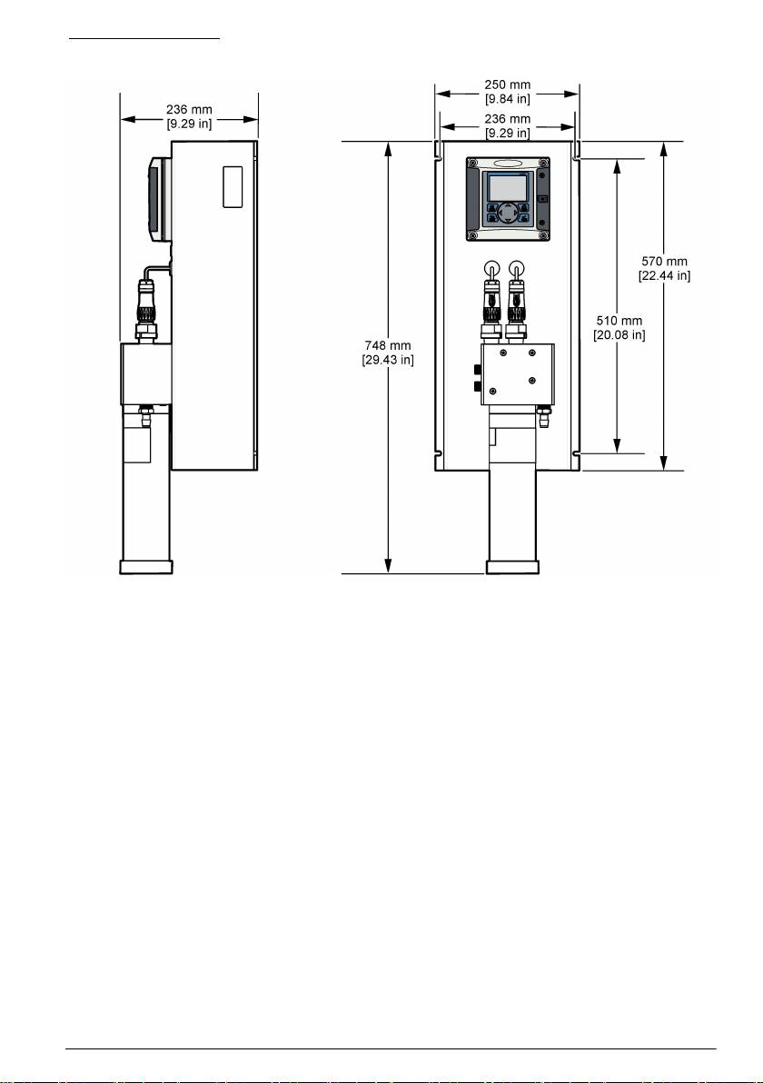
Figure 2 Dimensions
Resin cartridge installation
Refer to the steps that follow and Figure 3 to install the resin cartridge.
1. Insert the steel tube into the quick lock connector.
2. Push the steel tube as far as possible into the measuring cell.
3. Take the resin cartridge and turn it upside down 2 or 3 times until the resin comes away from the
sides of the cartridge and settles at the bottom, at the opposite end to the marker line.
4. Unscrew the cap off the top of the cartridge, by the marker line. Discard this cap and the flat black
sealing cap following the safety and disposal information for used cartridges.
5. Place the end of the steel tube into the center of the cartridge.
6. Slowly raise the cartridge to the measuring cell and screw into place to obtain an airtight and
watertight fitting.
English
9
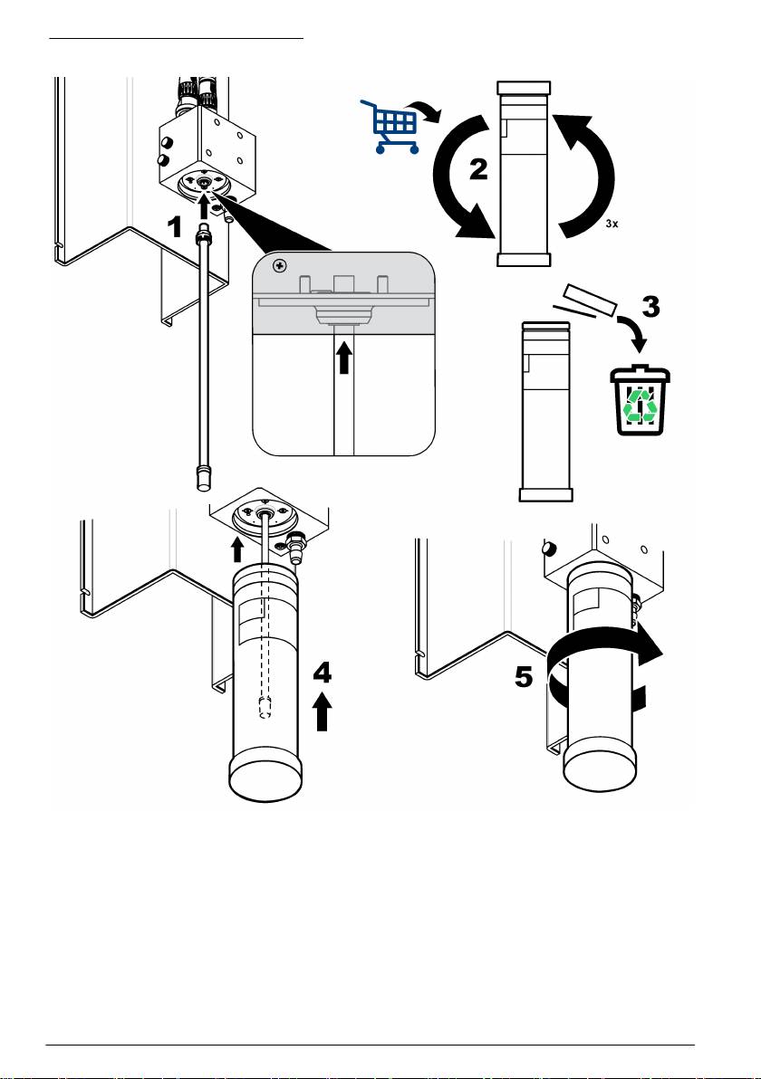
Figure 3 Resin cartridge installation
Wiring overview
Figure 4 shows an overview of the wiring connections inside the controller with the high voltage
barrier removed. The left side of the figure shows the back side of the controller cover.
Note: Remove connector caps from the connectors before module installation.
10
English
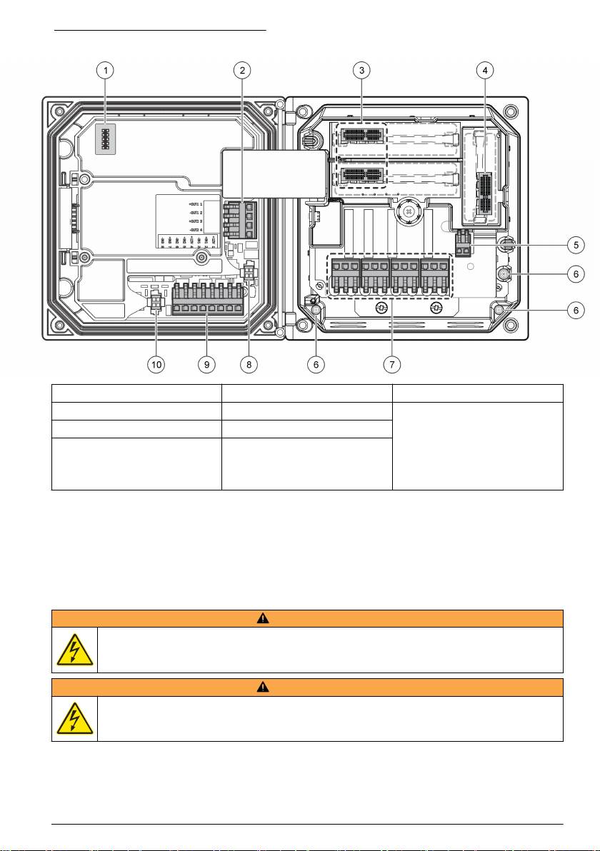
Figure 4 Wiring connections overview
1
1
1 Service cable connection 5 AC and DC power connector
9 Discrete input wiring connector
1
1
2 4-20 mA output
6 Ground terminals 10 Digital sensor connector
1
3 Sensor module connector 7 Relay connections
1
4 Communication module
8 Digital sensor connector
connector (e.g., Modbus,
Profibus, HART, optional
4-20 mA module, etc.)
1
Terminals can be removed for improved access.
High-voltage barrier
High-voltage wiring for the controller is located behind the high-voltage barrier in the controller
enclosure. The barrier must remain in place except when installing modules or when a qualified
installation technician is wiring for power, alarms, outputs or relays. Do not remove the barrier while
power is applied to the controller.
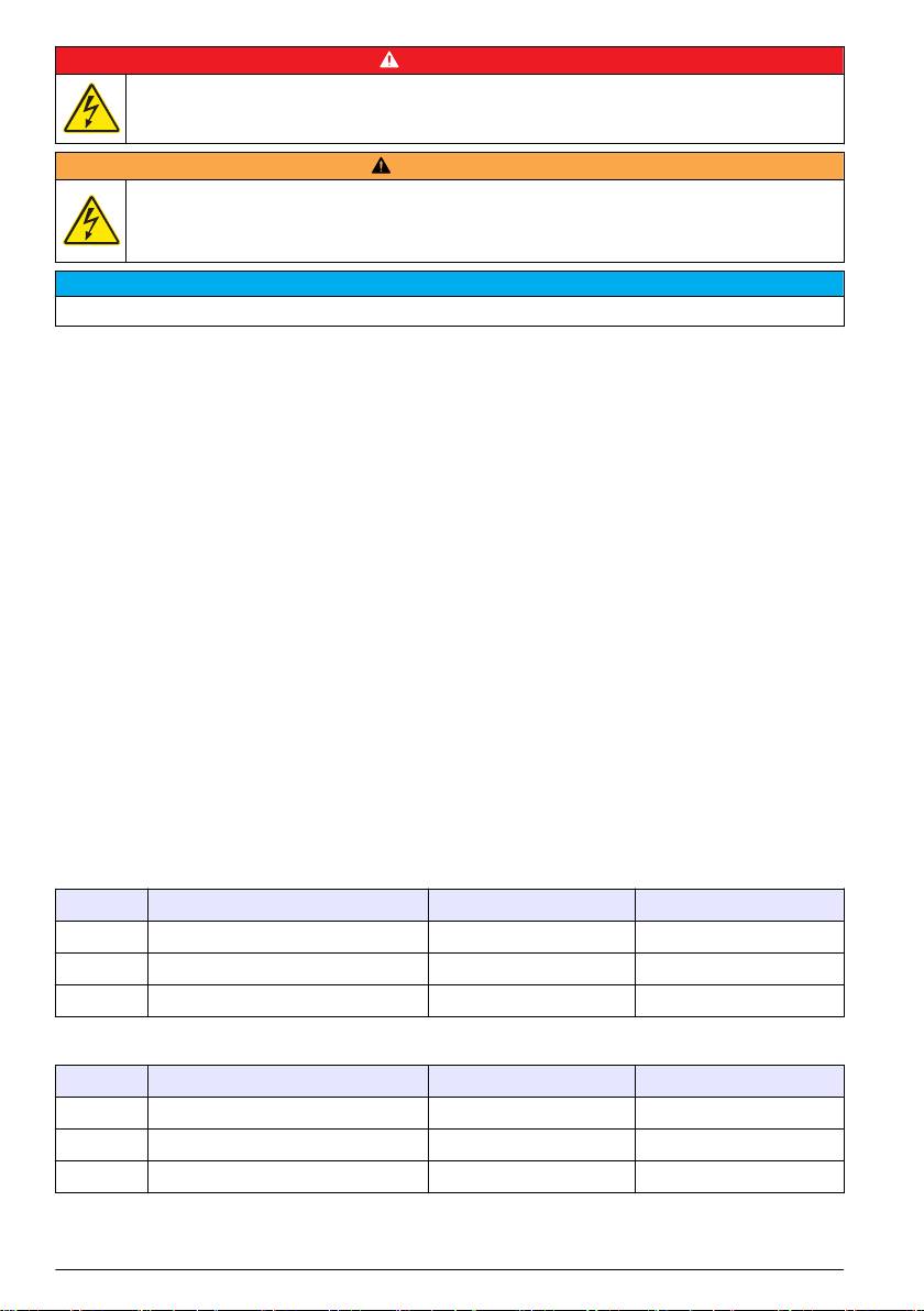
Wiring for power
W A R N I N G
Potential Electrocution Hazard. Always disconnect power to the instrument when making electrical
connections.
W A R N I N G
Potential Electrocution Hazard. If this equipment is used outdoors or in potentially wet locations, a
Ground Fault Interrupt device must be used for connecting the equipment to its mains power source.
English 11
D A N G E R
Electrocution Hazard. Do not connect AC power to a 24 VDC powered model.
W A R N I N G
Potential Electrocution Hazard. A protective earth (PE) ground connection is required for both
100-240 VAC and 24 VDC wiring applications. Failure to connect a good PE ground connection can
result in shock hazards and poor performance due to electromagnetic interferences. ALWAYS connect
a good PE ground to the controller terminal.
N O T I C E
Install the device in a location and position that gives easy access to the disconnect device and its operation.
The controller can be purchased as either a 100-240 VAC powered model or a 24 VDC powered
model. Follow the appropriate wiring instructions for the purchased model.
The controller can be wired for line power by hard-wiring in conduit or wiring to a power cord.
Regardless of the wire used, the connections are made at the same terminals. A local disconnect
designed to meet local electrical code is required and must be identified for all types of installation. In
hard-wired applications, the power and safety ground service drops for the instrument must be 18 to
12 AWG.
Notes:
• The voltage barrier must be removed before making any electrical connections. After making all
connections, replace the voltage barrier before closing the controller cover.
• A sealing type strain relief and a power cord less than 3 meters (10 feet) in length with three 18-
gauge conductors (including a safety ground wire) can be used to maintain the NEMA
4X/IP66 environmental rating.
• Controllers can be ordered with AC power cords pre-installed. Additional power cords may also be
ordered.
• The DC power source that supplies power to the 24 VDC powered controller must maintain
voltage regulation within the specified 24 VDC-15% +20% voltage limits. The DC power source
must also provide adequate protection against surges and line transients.
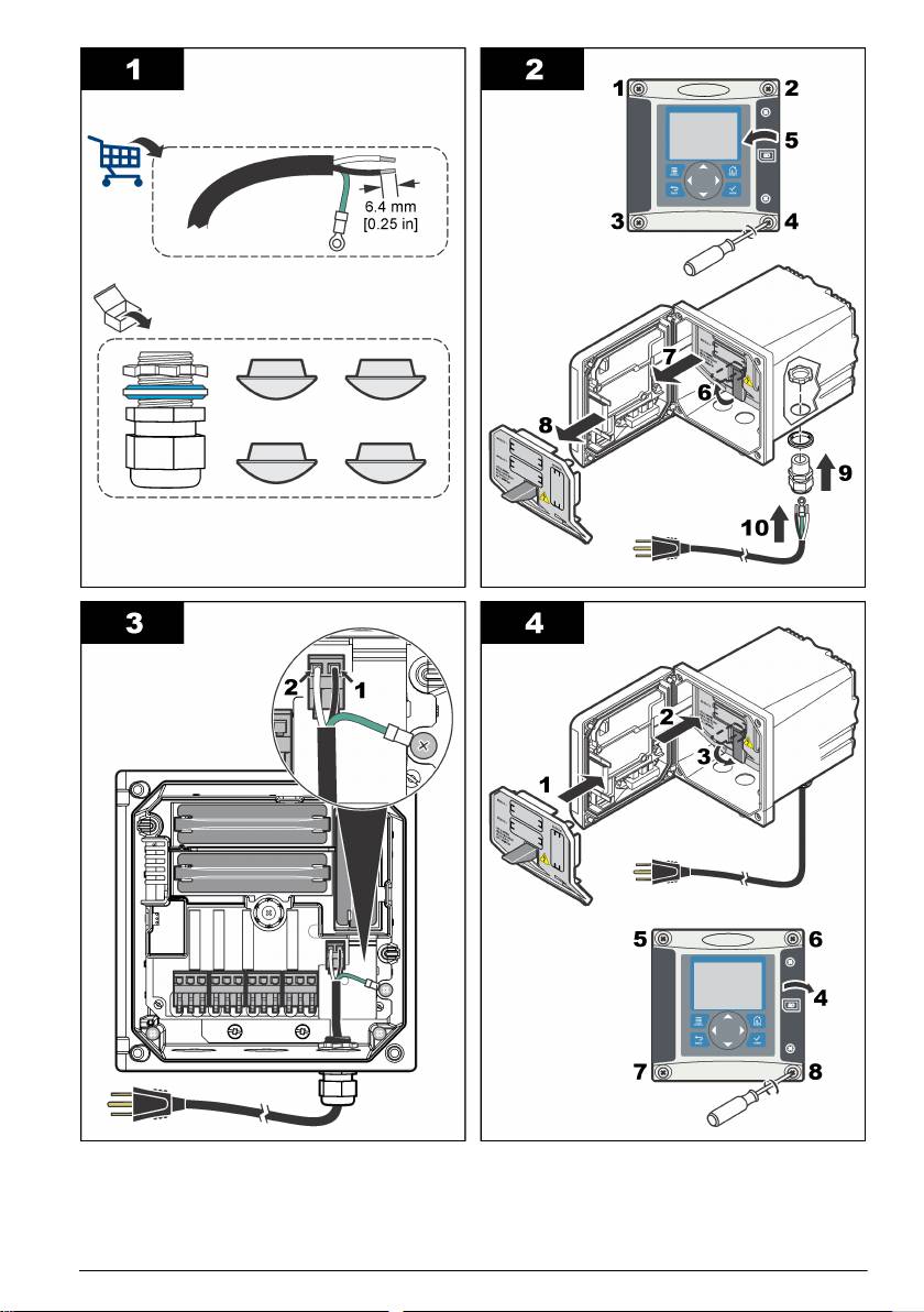
Wiring procedure
Refer to the illustrated steps that follow and Table 1 or Table 2 to wire the controller for power. Insert
each wire into the appropriate terminal until the insulation is seated against the connector with no
bare wire exposed. Tug gently after insertion to make sure that there is a secure connection. Seal
any unused openings in the controller box with conduit opening sealing plugs.
Table 1 AC power wiring information (AC powered models only)
Terminal Description Color—North America Color—EU
1 Hot (L1) Black Brown
2 Neutral (N) White Blue
— Protective Earth (PE) Ground lug Green Green with yellow stripe
Table 2 DC power wiring information (DC powered models only)
Terminal Description Color—North America Color—EU
1 +24 VDC Red Red
2 24 VDC return Black Black
— Protective Earth (PE) Ground lug Green Green with yellow stripe
12 English
Alarms and relays
The controller is equipped with four unpowered, single pole relays rated 100-250 VAC, 50/60 Hz,
5 amp resistive maximum. Contacts are rated 250 VAC, 5 amp resistive maximum for the AC
English
13
powered controller and 24 VDC, 5A resistive maximum for the DC powered controller. The relays are
not rated for inductive loads.
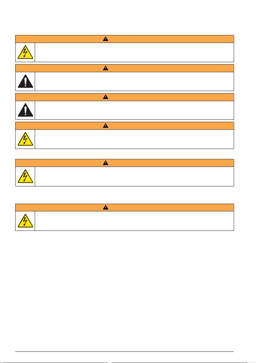
Wiring relays
W A R N I N G
Potential Electrocution Hazard. Always disconnect power to the instrument when making electrical
connections.
W A R N I N G
Potential fire hazard. The relay contacts are rated 5A and are not fused. External loads connected to
the relays must have current limiting devices provided to limit current to < 5 A.
W A R N I N G
Potential fire hazard. Do not daisy-chain the common relay connections or jumper wire from the mains
power connection inside the instrument.
W A R N I N G
Potential electrocution hazard. In order to maintain the NEMA/IP environmental ratings of the
enclosure, use only conduit fittings and cable glands rated for at least NEMA 4X/IP66 to route cables in
to the instrument.
AC line (100—250 V) powered controllers
W A R N I N G
Potential electrocution hazard. AC mains powered controllers (115 V–230 V) are designed for relay
connections to AC mains circuits (i.e., voltages greater than 16 V-RMS, 22.6 V-PEAK or 35 VDC).
The wiring compartment is not designed for voltage connections in excess of 250 VAC.
24 VDC powered controllers
W A R N I N G
Potential electrocution hazard. 24 V powered controllers are designed for relay connections to low
voltage circuits (i.e., voltages less than 16 V-RMS, 22.6 V-PEAK or 35 VDC).
The 24 VDC controller relays are designed for the connection to low voltage circuits (i.e., voltages
less than 30 V-RMS, 42.2 V-PEAK or 60 VDC). The wiring compartment is not designed for voltage
connections above these levels.
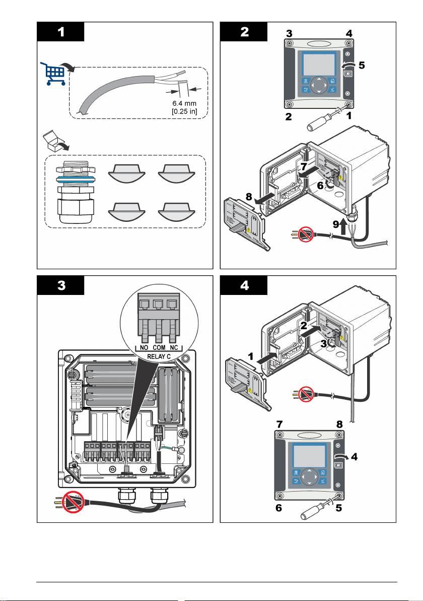
The relay connector accepts 18–12 AWG wire (as determined by load application). Wire gauge less
than 18 AWG is not recommended.
The Normally Open (NO) and Common (COM) relay contacts will be connected when an alarm or
other condition is active. The Normally Closed (NC) and Common relay contacts will be connected
when an alarm or other condition is inactive (unless the Fail Safe is set to Yes) or when power is
removed from the controller.
Most relay connections use either the NO and COM terminals or the NC and COM terminals. The
numbered installation steps show connection to the NO and COM terminals.
14
English
English 15
Analog output connections
W A R N I N G
Potential Electrocution Hazard. Always disconnect power to the instrument when making electrical
connections.
W A R N I N G
Potential electrocution hazard. In order to maintain the NEMA/IP environmental ratings of the
enclosure, use only conduit fittings and cable glands rated for at least NEMA 4X/IP66 to route cables in
to the instrument.
Two isolated analog outputs (1 and 2) are provided (Figure 5). Such outputs are commonly used for
analog signaling or to control other external devices.
Make wiring connections to the controller as shown in Figure 5 and Table 3.
Note: Figure 5 shows the back of the controller cover and not the inside of the main controller compartment.
Table 3 Output connections
Recorder wires Circuit board position
Output 2– 4
Output 2+ 3
Output 1– 2
Output 1+ 1
1. Open the controller cover.
2. Feed the wires through the strain relief.
3. Adjust the wire as necessary and tighten the strain relief.
4. Make connections with twisted-pair shielded wire and connect the shield at the controlled
component end or at the control loop end.
• Do not connect the shield at both ends of the cable.
• Use of non-shielded cable may result in radio frequency emission or susceptibility levels higher
than allowed.
• Maximum loop resistance is 500 ohm.
5. Close the controller cover and tighten the cover screws.
6. Configure outputs in the controller.
16
English
Оглавление
- English..............................................................................................................................3 Deutsch..........................................................................................................................25 Italiano............................................................................................................................48 Français.........................................................................................................................71 Español..........................................................................................................................94 Português....................................................................................................................118 中文...............................................................................................................................141 Nederlands.................................................................................................................160 Polski............................................................................................................................184 Suomi............................................................................................................................207 Русский........................................................................................................................229
- Table of contents
- General information
- Installation
- Analyzer startup
- Operation
- Maintenance
- Troubleshooting
- Inhaltsverzeichnis
- Allgemeine Informationen
- Installation
- Analysator starten
- Benutzeroberfläche und Navigation
- Wartung
- Fehlerbehebung
- Sommario
- Informazioni generali
- Installazione
- Avvio dell'analizzatore
- Interfaccia utente e navigazione
- Manutenzione
- Risoluzione dei problemi
- Table des matières
- Généralités
- Installation
- Mise en marche de l'analyseur
- Interface utilisateur et navigation
- Entretien
- Recherche de panne
- Tabla de contenidos
- Información general
- Instalación
- Inicio del analizador
- Interfaz del usuario y navegación
- Mantenimiento
- Solución de problemas
- Índice
- Informação geral
- Instalação
- Arranque do analisador
- Interface do utilizador e navegação
- Manutenção
- Resolução de problemas
- 目录
- 基本信息
- 安装
- 启动分析仪
- 操作
- 维护
- 故障排除
- Inhoudsopgave
- Algemene informatie
- Installatie
- Opstarten analysator
- Gebruikersinterface en navigatie
- Onderhoud
- Foutenopsporing
- Spis treści
- Instalacja
- Uruchamianie analizatora
- Interfejs użytkownika i nawigacja
- Konserwacja
- Rozwiązywanie problemów
- Sisällysluettelo
- Yleistietoa
- Asentaminen
- Analysaattorin käynnistäminen
- Käyttö
- Huolto
- Vianmääritys
- Содержание
- Общая информация
- Монтаж
- Запуск анализатора
- Пользовательский интерфейс и навигация
- Техническое обслуживание
- Выявление и устранение неисправностей
