Hotpoint-Ariston Style FH 831 C IX-HA: I nstallation
I nstallation: Hotpoint-Ariston Style FH 831 C IX-HA
1
4
GB
595 mm.
595 mm.
24 mm.
545 mm.
5 mm.
567 mm.
23 mm.
593 mm.
45 mm.
558 mm.
547
mm
. m
in.
I nstallation
560 m
m.
45 mm.
Before placing your new appliance into operation
please read these operating instructions carefully.
They contain important information for safe use, for
installation and for care of the appliance.
Please keep these operating instructions for future
reference. Pass them on to possible new owners of
the appliance.
P
o
s
itio
n
i
n
g
Keep packaging material out of the reach of
children.
It can become a choking or suffocation
hazard.
see Precautions and tips
).
!
The appliance must be installed by a qualified
person in compliance with the instructions provided.
Incorrect installation may cause harm to persons,
animals or may damage property.
F
ittin
g
t
h
e
a
pp
lian
c
e
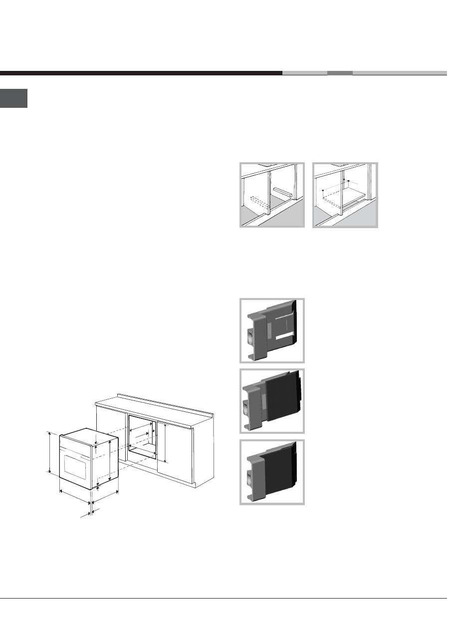
Use the appropriate cabinet to ensure that the
appliance functions properly.
The panels adjacent to the oven must be made of
heat-resistant material.
Cabinets with a veneer exterior must be assembled
with glues which can withstand temperatures of up
to 100°C.
To install the oven
u
n
d
e
r
t
h
e
c
o
u
nte
r
(
see diagram
)
and in a
k
it
c
h
en
u
nit
, the cabinet must have the
following dimensions:
!
The appliance must not come into contact with
electrical parts once it has been installed.
The consumption indications on the data plate have
been calculated for this type of installation.
V
entilation
To ensure good ventilation, the back panel of the
cabinet must be removed. It is advisable to install the
oven so that it rests on two strips of wood, or on a
completely flat surface with an opening of at least 45 x
560 mm (
see diagrams
).
C
ent
r
in
g
an
d
f
astenin
g
Position the 4 tabs on the side of the oven according
to the 4 holes of the outer frame. Adjust the tabs
according to the thickness of the cabinet side panel,
as shown below:
thickness of 20 mm: take off
the removable part of the tab
(
see diagram
)
thickness of 18 mm: use the
first groove, which has already
been set in the factory (
see
diagram
)
thickness of 16 mm: use the
second groove (
see diagram
)
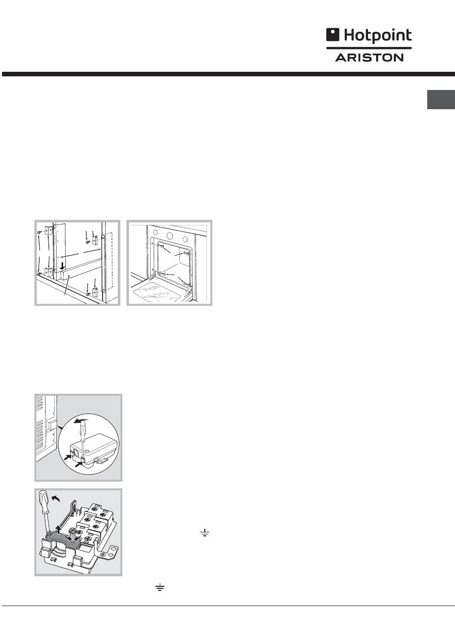
Secure the appliance to the cabinet by opening the
oven door and putting 4 screws into the 4 holes of the
outer frame.
!
All parts which ensure the safe operation of the
appliance must not be removable without the aid of a
tool.
1
5
GB
C
ent
r
in
g
an
d
f
i
x
in
g
*
1. Position brackets
A
against oven support
B
.
2. Position tabs
C
against brackets
A
. If the
thickness of the cabinet side panel:
is 16 mm thick: place the tab so that the
number 16 written on it is facing you;
is 18 mm thick: place the tab so that the part
without any text is facing you;
is 20 mm thick: do not fit the tab.
3. Fix the brackets and tabs onto the edge of the
cabinet side panel using screws
D.
4. Fix the oven to the cabinet using the screws and
plastic washers
E
.
E
l
e
c
t
r
i
c
al
c
o
nne
c
tio
n
s
!
Ovens equipped with a three-pole power supply
cable are designed to operate with alternating
current at the voltage and frequency indicated on
the data plate located on the appliance (
see below
).
F
ittin
g
t
h
e
p
o
w
e
r
s
u
pp
l
y
c
a
b
le
1. Open the terminal
board by inserting a
screwdriver into the
side tabs of the cover.
Use the screwdriver as
a lever by pushing it
down to open the cover
(
see diagram
).
2. Loosen the cable
clamp screw and
remove it, using a
screwdriver as a lever
(see figure).
3. Remove the wire
contact screws L-N-
, then fasten the wires
under the screw heads,
respecting the colour
code: Blue (N), Brown
(L) and Yellow-Green
Verde ( ).
C
onne
c
tin
g
t
h
e
s
u
pp
l
y
c
a
b
le
to
t
h
e
m
ains
Install a standardised plug corresponding to the
load indicated on the data plate (
see side
).
The appliance must be directly connected to the mains
using an omnipolar circuit-breaker with a minimum
contact opening of 3 mm installed between the appliance
and the mains, suitable for the load indicated and
complying with current electrical regulations (the earthing
wire must not be interrupted by the circuit-breaker). The
supply cable must not come into contact with surfaces
with temperatures higher than 50°C.
!
The installer must ensure that the correct electrical
connection has been made and that it is compliant
with safety regulations.
Before connecting to the power supply, make sure that:
The appliance is earthed and the plug is compliant
with the law.
The socket can withstand the maximum power of
the appliance, which is indicated on the data plate
(
see below
).
The voltage must be in the range between the
values indicated on the data plate (
see below
).
The socket is compatible with the plug of the
appliance. If the socket is incompatible with the
plug, ask an authorised technician to replace it. Do
not use extension cords or multiple sockets.
!
Once the appliance has been installed, the power
supply cable and the electrical socket must be easily
accessible.
!
The cable must not be bent or compressed.
!
The cable must be checked regularly and replaced
by authorised technicians only (
see Assistance
).
! The manufacturer declines any liability should
these safety measures not be observed.
* Only on certain models.
E
E
D
A
B
D
D
16
16
16
16
C
C
C
Оглавление
- I nstallazione
- Descrizionedellapparecchio
- A vvio e u tilizzo
- I l programmmatore di cottura elettronico
- Pro g rammi
- P reca u zioni e consi g li
- M an u tenzione e c u ra
- Assist en za
- O p eratin g Instr u c tions
- I nstallation
- D escri p tion o f t h e a pp liance
- Start - u p and u se
- T h e electronic coo k in g p ro g rammer
- C oo k in g modes
- P r e c a u tio n s a n d ti p s
- M aintenance and care
- M ode d emploi
- I nstallation
- Description de l appareil
- M ise en marc h e et u tilisation
- L e pro g rammate u r de c u isson é lectroni q u e
- Pro g rammes
- P r é ca u tions et conseils
- N etto y a g e et entretien
- M anual de instrucciones
- I nstalaci ó n
- D escri p ci ó n del a p arato
- P u esta en f u ncionamiento y u so
- E l p ro g ramador de cocci ó n electr ó nico
- P ro g ramas
- P r e c a uc io ne s y c o n s e j o s
- M antenimiento y c u idados
- I nstr u ç õ es para u tiliza ç ã o
- I nstala ç ã o
- Descri ç ã o do aparelho
- I nício e u tiliza çã o
- O pro g ramador de cozed u ra electr ó nico
- P ro g ramas
- P reca u ç õ es e conselhos
- M an u ten çã o e c u idados
- È íñòðóêöèè ïî ýêñïëóàòàöèè
- Ì îíòà æ
- Î ïè ñ àíè å èçäåëèÿ
-  ê ëþ÷åíèå è ý ê ñïëóà ò à ö èÿ
- Ýëå êò ðîííûé ò àéìåð ïðî ã ðàììèðîâàíèÿ âûïå÷ ê è
- Ï ðî ã ðàììû
- Ï ðåäîñ ò îðî æ íîñ ò è è ðå ê îìåíäà ö èè
- Ò å õ íè÷åñ ê îå îáñëó æ èâàíèå è ó õ îä
