Hotpoint-Ariston BWMD 742: инструкция
Раздел: Бытовая, кухонная техника, электроника и оборудование
Тип: Стиральная Машина
Инструкция к Стиральной Машине Hotpoint-Ariston BWMD 742

GB
1
Contents
Installation, 2-3-4-5
Unpacking and levelling
Connecting the electricity and water supplies
The first wash cycle
Technical data
Instructions for the fitter
Description of the washing machine, 6-7
Control panel
Display
Running a wash cycle, 8
Wash cycles and functions, 9
Table of wash cycles
Wash functions
Detergents and laundry, 10
Detergent dispenser drawer
Preparing the laundry
Special wash cycles
Load balancing system
Precautions and tips, 11
General safety
Disposal
Opening the porthole door manually
Care and maintenance, 12
Cutting off the water or electricity supply
Cleaning the washing machine
Cleaning the detergent dispenser drawer
Caring for the door and drum of your appliance
Cleaning the pump
Checking the water inlet hose
Troubleshooting, 13
Service, 14
BWMD 742
Instructions for use
WASHING MACHINE
English,1
GB
ES
Español,29
Italiano,15
I
Русский,43
CIS
2
GB
!
This instruction manual should be kept in a safe place for
future reference. If the washing machine is sold, transferred
or moved, make sure that the instruction manual remains
with the machine so that the new owner is able to familiari-
se himself/herself with its operation and features.
!
Read these instructions carefully: they contain vital infor-
mation relating to the safe installation and operation of the
appliance.
Unpacking and levelling
Unpacking
1. Remove the washing machine from its packaging.
2. Make sure that the washing machine has not been
damaged during the transportation process. If it has been
damaged, contact the retailer and do not proceed any
further with the installation process.
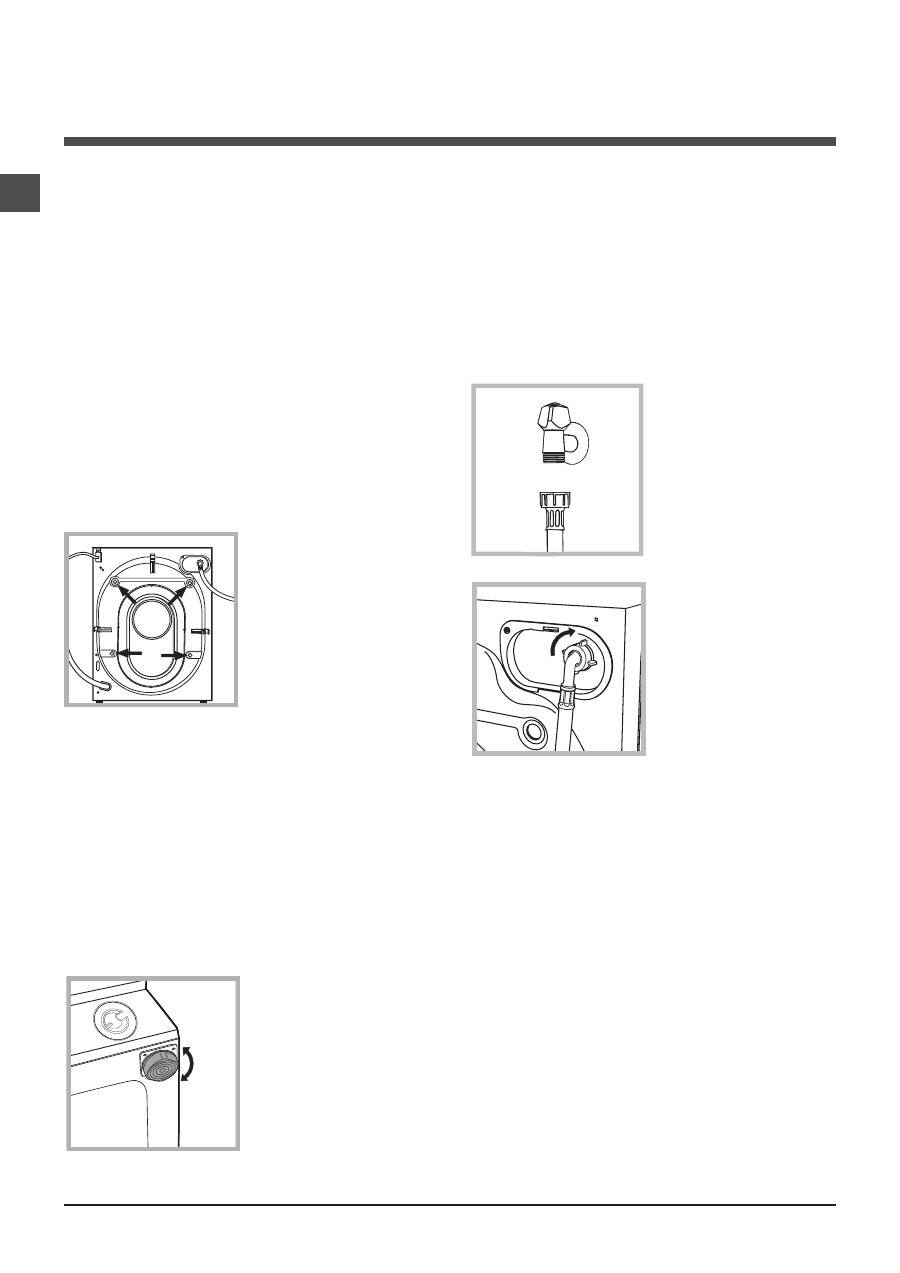
3. Remove the
4
protective
screws (used during tran-
sportation) and the rubber
washer with the correspon-
ding spacer, located on the
rear part of the appliance
(
see figure
).
4. Close off the holes using the plastic plugs provided.
5. Keep all the parts in a safe place: you will need them
again if the washing machine needs to be moved to ano-
ther location.
!
Packaging materials should not be used as toys for
children.
Levelling
1. Install the washing machine on a flat sturdy floor, without
resting it up against walls, furniture cabinets or anything
else.
2. If the floor is not perfectly
level, compensate for any
unevenness by tightening
or loosening the adjusta-
ble front feet (
see figure
);
the angle of inclination,
measured in relation to the
worktop, must not exceed
2°.
Levelling the machine correctly will provide it with stability,
help to avoid vibrations and excessive noise and prevent it
from shifting while it is operating. If it is placed on carpet or
a rug, adjust the feet in such a way as to allow a sufficient
ventilation space underneath the washing machine.
Connecting the electricity and water
supplies
Connecting the water inlet hose
1. Connect the supply pipe
by screwing it to a cold
water tap using a ¾ gas
threaded connection (see
figure).
Before performing the con-
nection, allow the water to
run freely until it is perfectly
clear.
2. Connect the inlet hose
to the washing machine by
screwing it onto the corre-
sponding water inlet of the
appliance, which is situa-
ted on the top right-hand
side of the rear part of the
appliance
(see figure)
.
3. Make sure that the hose is not folded over or bent.
!
The water pressure at the tap must fall within the values
indicated in the Technical details table
(see next page).
!
If the inlet hose is not long enough, contact a specialised
shop or an authorised technician.
!
Never use second-hand hoses.
!
Use the ones supplied with the machine.
Installation
GB
3
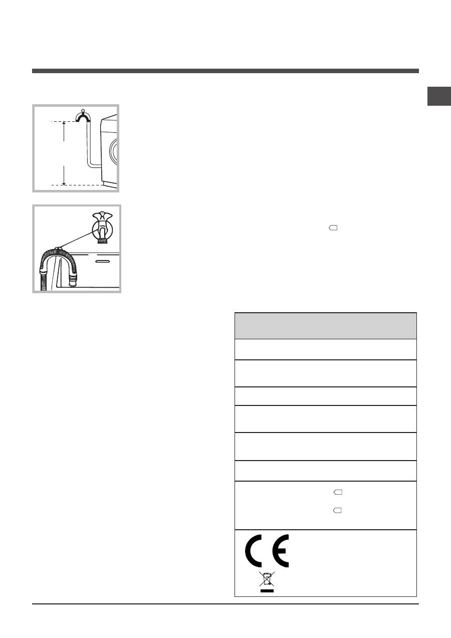
Connecting the drain hose
Connect the drain hose,
without bending it, to a drai-
nage duct or a wall drain
located at a height between
65 and 100 cm from the
floor;
alternatively, rest it on
the side of a washbasin
or bathtub, fastening the
duct supplied to the tap
(
see figure
). The free end
of the hose should not be
underwater.
!
We advise against the use of hose extensions; if it is
absolutely necessary, the extension must have the same
diameter as the original hose and must not exceed 150 cm
in length.
Electrical connections
Before plugging the appliance into the electricity socket,
make sure that:
• the socket is earthed and complies with all applicable
laws;
• the socket is able to withstand the maximum power load
of the appliance as indicated in the Technical data table
(see opposite);
• the power supply voltage falls within the values indicated
in the Technical data table
(see opposite);
• the socket is compatible with the plug of the washing
machine. If this is not the case, replace the socket or the
plug.
!
The washing machine must not be installed outdoors,
even in covered areas. It is extremely dangerous to leave
the appliance exposed to rain, storms and other weather
conditions.
!
When the washing machine has been installed, the elec-
tricity socket must be within easy reach.
!
Do not use extension cords or multiple sockets.
!
The cable should not be bent or compressed.
!
The power supply cable must only be replaced by autho-
rised technicians.
Warning! The company shall not be held responsible in the
event that these regulations are not respected.
The first wash cycle
Once the appliance has been installed, and before you use
it for the first time, run a wash cycle with detergent and no
laundry, using the wash cycle
(60°C).
65 - 100 cm
Technical data
Model
BWMD 742
Dimensions
width 59.5 cm
height 81.5 cm
depth 54.5 cm
Capacity
from 1 to 7 kg
Electrical
connections
please refer to the technical data plate
fixed to the machine
Water connections
maximum pressure 1 MPa (10 bar)
minimum pressure 0.05 MPa (0.5 bar)
drum capacity 52 litres
Spin speed
up to 1400 rotations per minute
Test wash cycles
in accordance
with directives
1061/2010 and
1015/2010
programme
(60°)
(
1st press of the button)
;
Standard Cotton 60°C
.
programme
(40°)
(
2nd press of the button)
;
Standard Cotton 40°C
.
This appliance conforms to the following
EC Directives:
- 2004/108/EC (Electromagnetic Compatibility)
- 2006/95/EC (Low Voltage)
- 2002/96/EC
4
GB
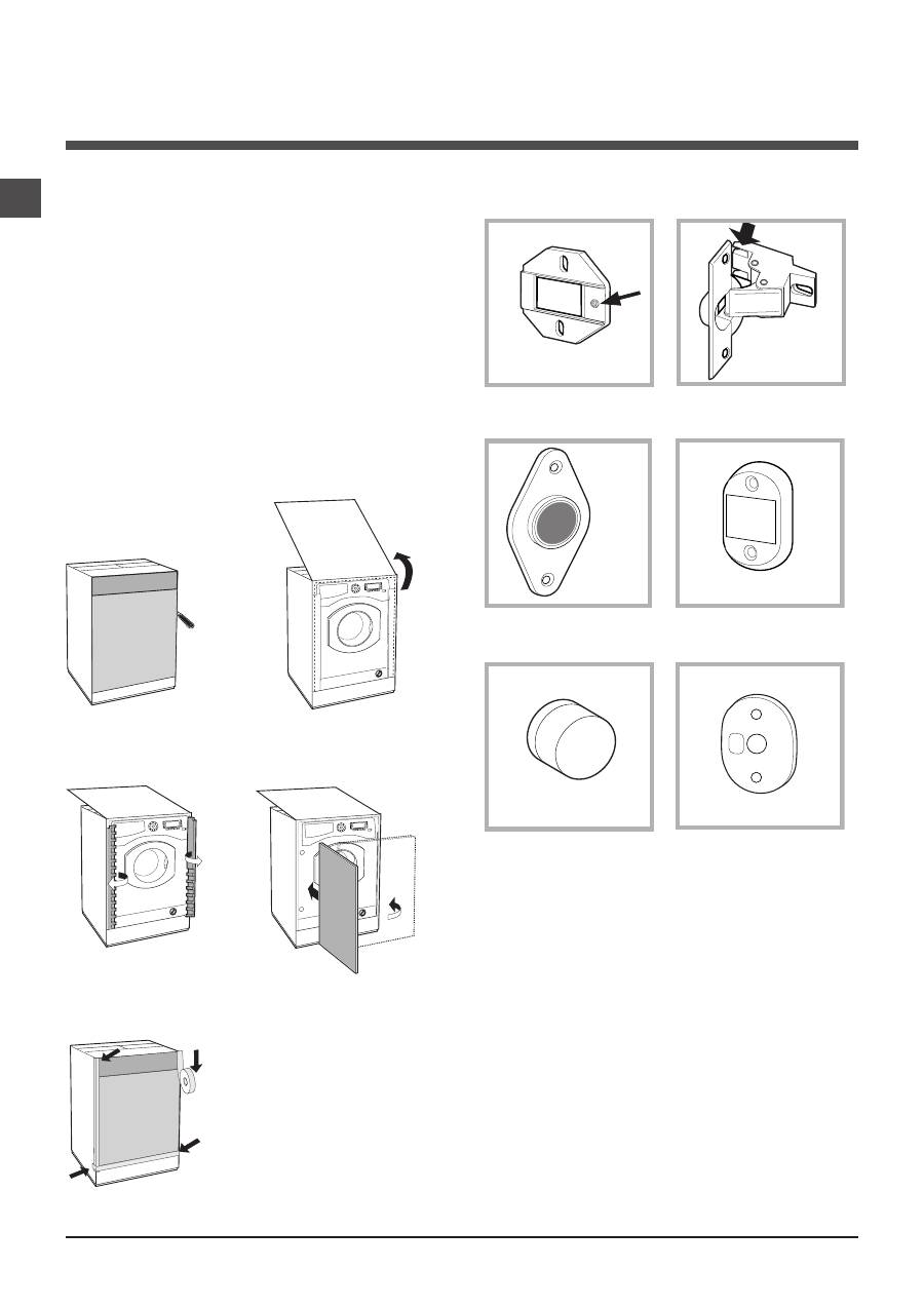
Instructions for the fitter
Mounting the wooden panel onto the door and inser-
ting the machine into cabinets:
In the case where the machine must be shipped for final
installation after the wooden panel has been mounted, we
suggest leaving it in its original packaging. The packaging was
designed to make it possible to mount the wooden panel
onto the machine without removing it completely
(see figures
below).
The wooden panel that covers the face of the machine must
not be less than
18 mm
in thickness and can be hinged on
either the right or left. For the sake of practicality when using
the machine, we recommend that the panel be hinged on the
same side as the door for the machine itself - the left.
A B C D E
Tur se
ite
Door Mounting Accessories
(Fig. 1-2-3-4-5).
Fig. 1
N° 2 Hinges
N° 1 Magnet
N° 1 Magnet plate
N° 1 Rubber plug
N° 2 Hinge Supports
N° 4 Spacers
Fig. 2
Fig. 3
Fig. 4
Fig. 5
Fig. 4/B
- No. 6 type
A
self-threading screws, l =13 mm.
- No. 2 type
B
metric, countersunk screws, l =25; for faste-
ning the magnet plate to the cabinet.
- No. 4 type
C
metric screws, l =15 mm; for mounting the
hinge supports to the cabinet.
- No. 4 type
D
metric screws, l =7 mm; for mounting the
hinges on the supports.
Mounting the Parts onto the Face of the Machine.
- Fit the hinge supports to the appliance front panel, positioning
the hole marked with an arrow in
fig. 1
so that it is on the inner
side of the front panel. Fit a spacer (
fig. 4/B)
between the
surfaces using type
C
screws.
- Fit the magnet plate at the top of the opposite side, using
type
B
screws to fix two spacers
(fig. 4/B)
between the plate
and the surface.
GB
5
Using the Drilling Template.
- To trace the positions of the holes on the left-hand side of
the panel, align the drilling template to the top left side of the
panel using the lines traced on the extremities as a reference.
- To trace the positions of the holes on the right-hand side of
the panel, align the drilling template to the top right side of the
panel.
- Use an appropriately sized router to mill the holes for the two
hinges, the rubber plug and the magnet.
Mounding the Parts onto the Wooden Panel (Door).
- Insert the hinges into the holes (the movable part of the hin-
ge must be positioned facing away from the panel) and fasten
them with the 4 type
A
screws.
- Insert the magnet into the top hole on the opposite side of
the hinges and fasten it with the two type
B
screws.
- Insert the rubber plug into the bottom hole.
The panel is now ready to be mounted onto the machine.
Mounting the Panel into the machine.
Insert the nib of the hinge (indicated by the arrow in
fig. 2
) into
the hole for the hinge and push the panel towards the front of
the machine. Fasten the two hinges with the type
D
screws.
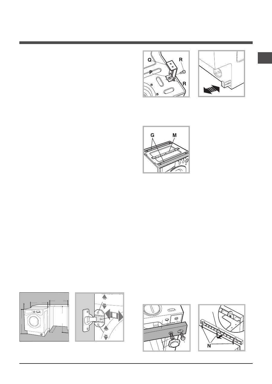
Fastening the plinth guide.
If the machine is installed at the end of a set of modular
cabinets, mount either one or both of the guides for the base
molding (as shown in
fig. 8
). Adjust them for depth based on
the position of the base molding, and, if necessary, fasten the
base to the guides
(fig. 9)
.
This is how to assemble the plinth guide
(fig. 8)
:
Fasten angle
P
using screw
R
, insert plinth guide
Q
into the
special slot and once it is in the desired position, lock it in
place using angle
P
and screw
R
.
Inserting the machine into the Cabinet.
- Push the machine into the opening, aligning it with the cabi-
nets
(fig. 6)
.
- Regulate the adjustable feet to raise the machine to the
appropriate height.
- To adjust the position of the wooden panel in both the
vertical and horizontal directions, use the
C
and
D
screws, as
shown in
fig. 7
.
Important:
close the lower part of the appliance front by
ensuring that the plinth rests against the floor.
Fig. 8
Fig. 9
Accessories provided for the height adjustment.
The following can be found inside the polystyrene lid
(fig. 10)
: 2
crossbars (
G
), 1 strip (
M
)
the following can be found inside
the appliance drum:
4 additional feet (
H
),
4 screws (
I
),
4 screws (
R
),
4 nuts (
L
),
2 plinth guides (
Q
)
Adjusting the appliance height.
The height of the appliance can be adjusted (from
815
mm to
835
mm), by turning the
4
feet.
Should you require the appliance to be placed higher than the
above height, you need to use the following accessories to
raise it to up to
870
mm:
the two crossbars (
G
); the 4 feet (
H
); the 4 screws (
I
); the 4
nuts (
L
) then perform the following operations
(fig. 11)
:
remove the
4
original feet, place a crossbar
G
at the front of the
appliance, fastening it in place using screws
I
(screwing them in
where the original feet were) then insert the new feet
H
.
Repeat the same operation at the back of the appliance.
Now adjust feet
H
to raise or lower the appliance from
835
mm
to
870
mm.
Once you have reached the desired height, lock nuts
L
onto
crossbar
G
.
To adjust the appliance to a height between
870
mm and
900
mm, you need to mount strip
M
, adjusting feet
H
to the requi-
red height.
Insert the strip as follows:
loosen the three screws
N
situated at the front of the Top cover
of the appliance, insert strip
M
as shown in
fig. 12
, then fasten
screws
N
.
D
C
C
570
mi
n
81
5
540
595
820 ÷ 900
600 min
Fig. 6
Fig. 7
L
I
H
G
M
Fig. 11
Fig. 12
Fig. 10
Оглавление
- Installation
- Description of the washing machine
- Running a wash cycle
- Wash cycles and functions
- Detergents and laundry
- Precautions and tips
- Care and maintenance
- Troubleshooting
- Service
- Istruzioni per l’uso
- Installazione
- Descrizione della lavabiancheria
- Come effettuare un ciclo di lavaggio
- Programmi e funzioni
- Detersivi e biancheria
- Precauzioni e consigli
- Manutenzione e cura
- Anomalie e rimedi
- Assistenza
- Manual de instrucciones
- Instalación
- Descripción de la lavadora
- Cómo efectuar un ciclo de lavado
- Programas y funciones
- Detergentes y ropa
- Precauciones y consejos
- Mantenimiento y cuidados
- Anomalías y soluciones
- Asistencia
- Руководство по эксплуатации
- Установка
- Описание стиральной машины
- Порядок выполнения цикла стирки
- Программы и функции
- Стиральные вещества и типы белья
- Предосторожности и рекомендации
- Техническое обслуживание и уход
- Неисправности и методы их устранения
- Сервисное обслуживание
