Hotpoint-Ariston C 3 VP6 R/HA: инструкция
Раздел: Бытовая, кухонная техника, электроника и оборудование
Тип: Плита
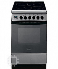
Инструкция к Плите Hotpoint-Ariston C 3 VP6 R/HA
Характеристики, спецификации
GB
COOKER AND OVEN
C3VP6R /HA
Operating Instructions
English, 1
GB
Ðóññêèé
, 12
R
S
Polski, 23
P
L
Magyar, 34
H
U
Cesky, 45
C
Z
Contents
Installation,
2-
3
Positioning and levelling
Electrical connection
Table of characteristics
Description
o
f
the
appliance,
4
Overall view
Control panel
S
tart
-
up
an
d
use,
5-8
Using the oven
Cooking modes
Practical cooking advice
Planning cooking with the programmer
Oven cooking advice table
U
sing
the
glass
cera
m
ic
ho
b
,
9
Switching the cooking zones on and off
Cooking zones
Precautions
an
d
tips,
1
0
General safety
Disposal
Respecting and conserving the environment
M
aintenance
an
d
care,
11
Switching the appliance off
Cleaning the appliance
Replacing the oven light bulb
Cleaning the glass ceramic hob
Assistance
2
GB
Before operating your new appliance please read
this instruction booklet carefully. It contains
important information concerning the safe installation
and operation of the appliance.
Please keep these operating instructions for future
reference. Make sure that the instructions are kept
with the appliance if it is sold, given away or moved.
The appliance must be installed by a qualified
professional according to the instructions provided.
Any necessary adjustment or maintenance must be
performed after the cooker has been disconnected
from the electricity supply.
Positioning
an
d
le
v
elling
It is possible to install the appliance alongside
cupboards whose height does not exceed that of the
hob surface.
Make sure that the wall in contact with the beck of
the appliance is made from a non-flammable, heat-
resistant material (T 90°C).
To install the appliance correctly:
Place it in the kitchen, dining room or the bed-sit
(not in the bathroom).
If the top of the hob is higher than the cupboards,
the appliance must be installed at least 200 mm
away from them.
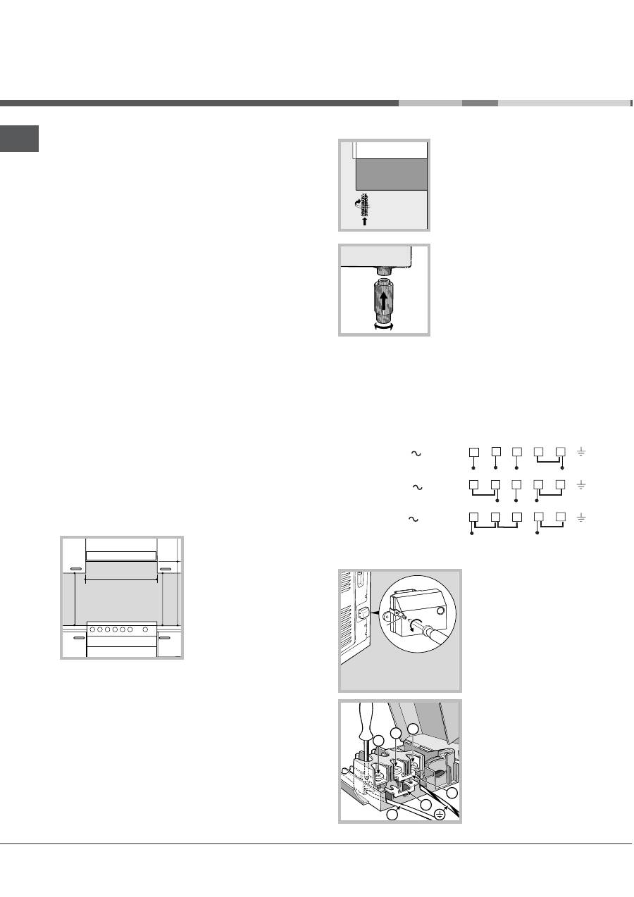
If the cooker is
installed underneath a
wall cabinet, there must
be a minimum distance
of 420 mm between this
cabinet and the top of
the hob.
This distance should be
increased to 700 mm if
the wall cabinets are
flammable (
see figure
).
Do not position blinds behind the cooker or less
than 200 mm away from its sides.
Any hoods must be installed according to the
instructions listed in the relevant operating manual.
L
evelling
If it is necessary to level the
appliance, screw the
adjustable feet into the places
provided on each corner of the
base of the cooker (
see
figure
).
The legs* fit into the slots on
the underside of the base of
the cooker.
E
le
ctr
i
ca
l
co
nne
ct
i
o
n
F
i
tt
ing
th
e
po
w
e
r
supp
l
y
ca
b
le
The cable should be suited to the type of electrical
connection used, according to the following
connection diagram:
1
2
3
4
5
1
2
3
4
5
1
2
3
4
5
R
S
T
N
R
S
N
R
N
400 3N
H05RR-F 5x2.5 CEI-UNEL 35363
400V 2N
H05RR-F 4x4 CEI-UNEL 35363
230V
H05RR-F 3x4 CEI-UNEL 35363
To install the power supply cable correctly:
1. Loosen the screw V
in the terminal board
and pull the cover to
open it (
see figure
).
2. Position the
connection supports A
(
see figure
) according
to the connection
diagram shown above.
The terminal board is
designed for single-
phase 230 V
connection: terminals 1,
2 and 3 are connected
I nstallation
HOOD
420
Min.
min.
650
mm. with hood
min.
700
mm. without hood
mm.
600
Min.
mm.
420
Min.
mm.
V
1
2
3
N
A
B
*
Only available in certain models.
GB
3
to each other; jumper 4-5 is located in the lower area
of the terminal board.
3. Position the wires N and
6
as shown in the
diagram (
see figure
) and proceed with the
connection process, tightening the terminal screws
as far as possible.
4. Position the remaining wires on terminals 1-2-3
and tighten the screws.
5. Fix the power supply cable in place by fastening
the cable clamp screw.
6. Close the terminal board cover by tightening the
screws V.
C
onnecting
the
supply
cable
to
the
mains
Install a standardised plug corresponding to the
load indicated on the appliance data plate (
see
Technical data table
).
The appliance must be directly connected to the mains
using an omnipolar circuit-breaker with a minimum
contact opening of 3 mm installed between the
appliance and the mains. The circuit-breaker must be
suitable for the charge indicated and must comply with
NFC 15-100 regulations (the earthing wire must not be
interrupted by the circuit-breaker). The supply cable
must be positioned so that it does not come into
contact with temperatures higher than 50°C at any point.
Before connecting the appliance to the power
supply, make sure that:
The appliance is earthed and the plug is compliant
with the law.
The socket can withstand the maximum power of
the appliance, which is indicated by the data
plate.
The voltage is in the range between the values
indicated on the data plate.
The socket is compatible with the plug of the
appliance. If the socket is incompatible with the
plug, ask an authorised technician to replace it.
Do not use extension cords or multiple sockets.
Once the appliance has been installed, the power
supply cable and the electrical socket must be
easily accessible.
The cable must not be bent or compressed.
The cable must be checked regularly and replaced
by authorised technicians only.
T
he
manufacturer
declines
any
liability
should
these
safety
measures
not
be
observed
.
*
Only available in certain models.
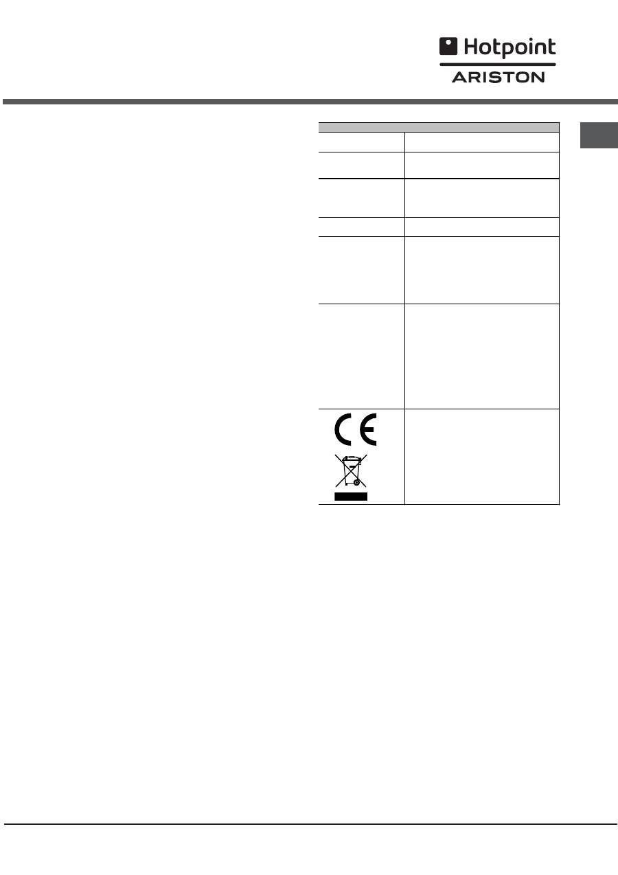
TABLE OF CHARACTERISTSICS
Dimensions
Oven HxDxW
34x41x38
Volume
53 l
Useful
measurements
relating to the oven
compartment
width 42 cm
depth 44 cm
height 17 cm
Voltage and
frequency
see data plate
Ceramic hob
Front Left
Back Left
Back Right
Front Right
Max. ceramic hob
consumption
1200 W
1800 W
1200 W
1800 W
6000 W
ENERGY LABEL
Directive 2002/40/EC on the label of
electric ovens.
Standard EN 50304
Energy consumption for Natural
convection – heating mode:
a
Traditional mode;
Declared energy consumption for
Forced convection Class – heating
mode:
u
Baking mode.
This appliance conforms to the following
European Economic Community
directives: 73/23/EEC dated 19/02/73
(Low Voltage) and subsequent
amendments - 89/336/EEC dated
03/05/89 (Electromagnetic
Compatibility) and subsequent
amendments - 93/68/EEC dated
22/07/93 and subsequent amendments.
2002/96/EEC
4
GB
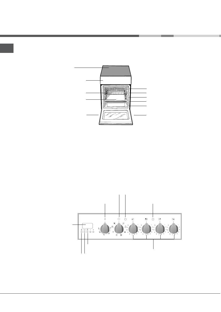
D e scription of the appliance
Overall
view
Control
panel
Control panel
GRILL
rack
DRIPPING PAN
GUIDE RAILS
for the sliding racks
position 3
position 2
position 1
Glass
ceramic hob
Adjustable
foot
Adjustable
foot
position 5
position 4
Electronic
cooking
programmer
TIMER
button
COOKING END TIME
button
COOKING TIME
button
THERMOSTAT
knob
HOTPLATES
indicator light
HOTPLATES
knob
SELECTOR
knob
THERMOSTAT
indicator light
Оглавление
- I nstallation
- D e scription of the appliance
- S tart -u p an d u s e
- U sin g the glass ceramic hob
- Preca u tions an d ti p s
- C are a n d mai n te n a n ce
- Ð óêîâîäñòâî ïî ýêñïëóàòàöèè
- Ó ñ ò àí î âêà
- Î ï èñàíèå è çä å ë è ÿ
- Â ê ë þ ÷ åíèå è ý êñ ïë ó à ò à ö è ÿ
- Ñò åê ëî êåðà ì è ÷ åñêà ÿ âàð î÷ íà ÿ ï àíå ëü
- Ïðå äî ñ òî ð îæ í î ñ ò è è ðåê îì åí ä à ö èè
- Ò å õ íè ÷ åñê î å îá ñ ë ó æ èâàíèå è ó õîä
- I nstrukcja o b s³ugi
- I nstala c j a
- O pis u rz¹dz enia
- U r u c h o m ienie i u¿y t k owanie
- U ¿y t k owanie c e r a m i cz ne j p ³ y t y g rz e j ne j
- Z ale c enia i r o d k i ost r o ¿ no c i
- K onse r wa c j a i u t rz y m anie
- Návod k instalaci a obsluze
- Instalace
- Popis spotřebiče
- Uvedení do chodua používání
- Použití sklokeramickévarné desky
- Opatření a rady
- Péče a údržba


