Vitek VT-3539: Remote sensors: OPERATING CONTROLS
Remote sensors: OPERATING CONTROLS: Vitek VT-3539
Table of contents
- WEATHER STATION USER INSTRUCTIONS Features: Block with main display:
- Remote sensors: OPERATING CONTROLS
- READ BEFORE USING For best results: GETTING STARTED Step 1: Setting up the remote sensor:
- Step 2: Receiver settings SYNCHRONIZING THE OUTDOOR TEMPERATURE READING Auto-detect function: Manual learning function (Search for remote sensor signals):
- SETTING THE TIME AND ALARM Setting the time:
- WEATHER CONDITIONS DISPLAY
- Hi and Lo symbols on the display Temperature trend indicator The temperature trend indicator shows the temperature trend registered by a separate sensor over the past half-hour. TEMPERATURE CONDITIONS REPORT Temperature conditions reporting symbols Black ice warning
- TEMPERATURE ALARM SETTINGS High temperature alarm Low temperature alarm When the alarm will be heard
- BACKLIGHT USING AN EXTERNAL WIRED SENSOR LOW BATTERY INDICATOR Receiver:
- Remote sensor:
- RESOLVING MALFUNCTIONS Problem Resolution
- TECHNICAL CHARACTERISTICS Meteorological station receiver Meteorological station remote sensor MINIMUM SERVICE LIFE - 3 YEARS
ENGLISH
• Indications in Celsius or Fahrenheit
• Battery type: 2 x AA
Remote sensors:
• Weather-proof construction with liquid crystal display
• Jack for connecting external sensor
• External wired sensor
• Display of temperature readings in Celsius or Fahrenheit,
• Humidity display
• Transmission distance: up to 40 m in an open area
• Battery type: 2 x AA
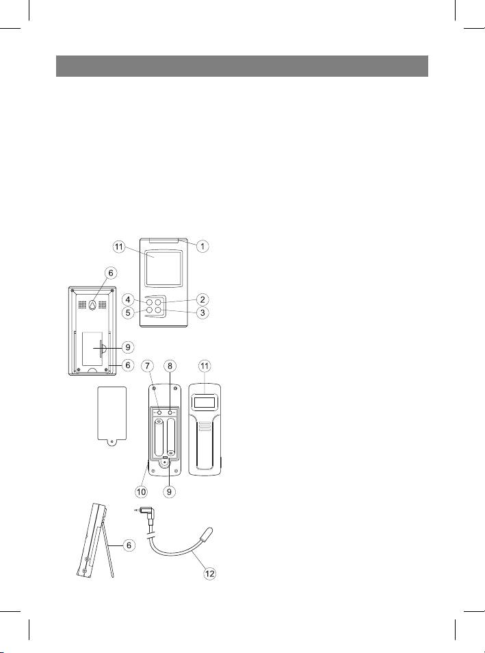
OPERATING CONTROLS
1. Mode/Snooze – switching display modes
between time, alarm, high and low tempera-
ture alarms in temperature control points;
temporary alarm deactivation.
2. Hour/+/Max – hour advance; maximum
temperature display.
3. Minute/-/Min – minutes advance; mini-
mum temperature display.
4. Alarm/°C/°F – switching between Celsius
and Fahrenheit, between 12-hour and 24-
hour time format, turning the alarm on and
off, erasing previous temperature alarm set-
tings.
5. Channel – switching between remote
control channels (from 1 to 4)
6. Wall mount and tabletop stand
7. SET: entering the home code and activat-
ing the channel settings mode
8. C/F: switching from °C to °F, changing the
channel or home code
9. Battery compartment
10. External sensor jack
11 . Liquid crystal display
12 . External wired sensor
3
35391.indd 335391.indd 3 23.05.2006 17:08:5123.05.2006 17:08:51


