Ridgid NaviTrack II: инструкция
Раздел: Электроинструменты
Тип:
Инструкция к Ridgid NaviTrack II


NaviTrack® II
1
General Safety Information
WARNING!
Read these instructions
and the accompanying safety booklet
carefully before using this equipment.
If you are uncertain about any aspect of
using this tool, contact your RIDGID distributor
for more information.
Failure to understand and follow all instructions
may result in electric shock, fire, and/or serious
personal injury.
SAVE THESE INSTRUCTIONS!
•
Do not probe high voltage lines
.
Battery Precautions
•
Use only the size and type of battery specified. Do
not mix cell types (e.g. do not use alkaline with
rechargeable).
Do not use partly discharged and fully
charged cells together (e.g. do not mix old and new).
•
Recharge batteries with charging units specified by the
battery manufacturer.
Using an improper charger can
overheat and rupture the battery.
•
Properly dispose of the batteries.
Exposure to high
temperatures can cause the battery to explode, so do
not dispose of in a fire. Some countries have regulations
concerning battery disposal. Please follow all applicable
regulations.
Personal Safety
•
Use proper accessories.
Do not place this product on
any unstable cart or surface. The product may fall causing
serious injury to a child or adult or serious damage to the
product.
•
Prevent object and liquid entry.
Never spill liquid of any
kind on the product. Liquid increases the risk of electrical
shock and damage to the product.
•
Avoid Traffic. Pay close attention to moving vehicles
when using on or near roadways. Wear visible clothing
or reflector vests.
Such precautions may prevent serious
injury.
NaviTrack® II Use and Care
•
Use equipment only as directed.
Do not operate the
NaviTrack® II unless you have read the owner manual
and been trained in its use.
•
Do not immerse the antennas in water. Store in a
dry place.
This will reduce the risk of electric shock and
instrument damage.
•
Store idle equipment out of the reach of children and
other untrained persons.
Equipment is dangerous in
the hands of untrained users.
•
Maintain the instrument with care.
Properly
maintained diagnostic instruments are less likely to
cause injury.

NaviTrack® II
2
•
Service
•
Diagnostic instrument service must be performed only
by qualified repair personnel.
Service or maintenance
performed by unqualified repair personnel could result in
injury.
•
When servicing a diagnostic instrument, use only
identical replacement parts.
Follow instructions in the
maintenance section of this manual. Use of unauthorized
parts or failure to follow maintenance instructions may
create a risk of electrical shock or injury.
•
Conduct a safety check.
Upon completion of any service
or repair of this product, ask the service technician to
perform safety checks to determine that the product is in
proper operating condition.
•
Damage to the product that requires service.
Remove
the batteries and refer servicing to qualified service
personnel under any of the following conditions:
o If liquid has been spilled or objects have fallen into
product;
o If product does not operate normally by following the
operating instructions;
o If the product has been dropped or damaged in any
way;
o When the product exhibits a distinct change in
performance.
If you have any questions regarding the service or repair of this
machine, contact your distributor or Ridge Tool directly.
In any correspondence, please give all the information shown
on the nameplate of your tool including model number and
serial number.
Important Notice
The NaviTrack® II is a diagnostic tool that senses electro-
magnetic fields emitted by objects underground. It is meant
to aide the user in locating these objects by recognizing
characteristics of the field lines and displaying them on
the screen. As electromagnetic field lines can be distorted
and interfered with, it is important to verify the location of
underground objects before digging.
Several utilities may be underground in the same area.
Be sure to follow local guidelines and one-call service
procedures.
Exposing the utility is the only way to verify its existence,
location and depth.
Ridge Tool Co., its affiliates and suppliers, will not be
liable for any injury or any direct, indirect, incidental or
consequential damages sustained or incurred by reason of
the use of the NaviTrack® II.
NaviTrack® II
3
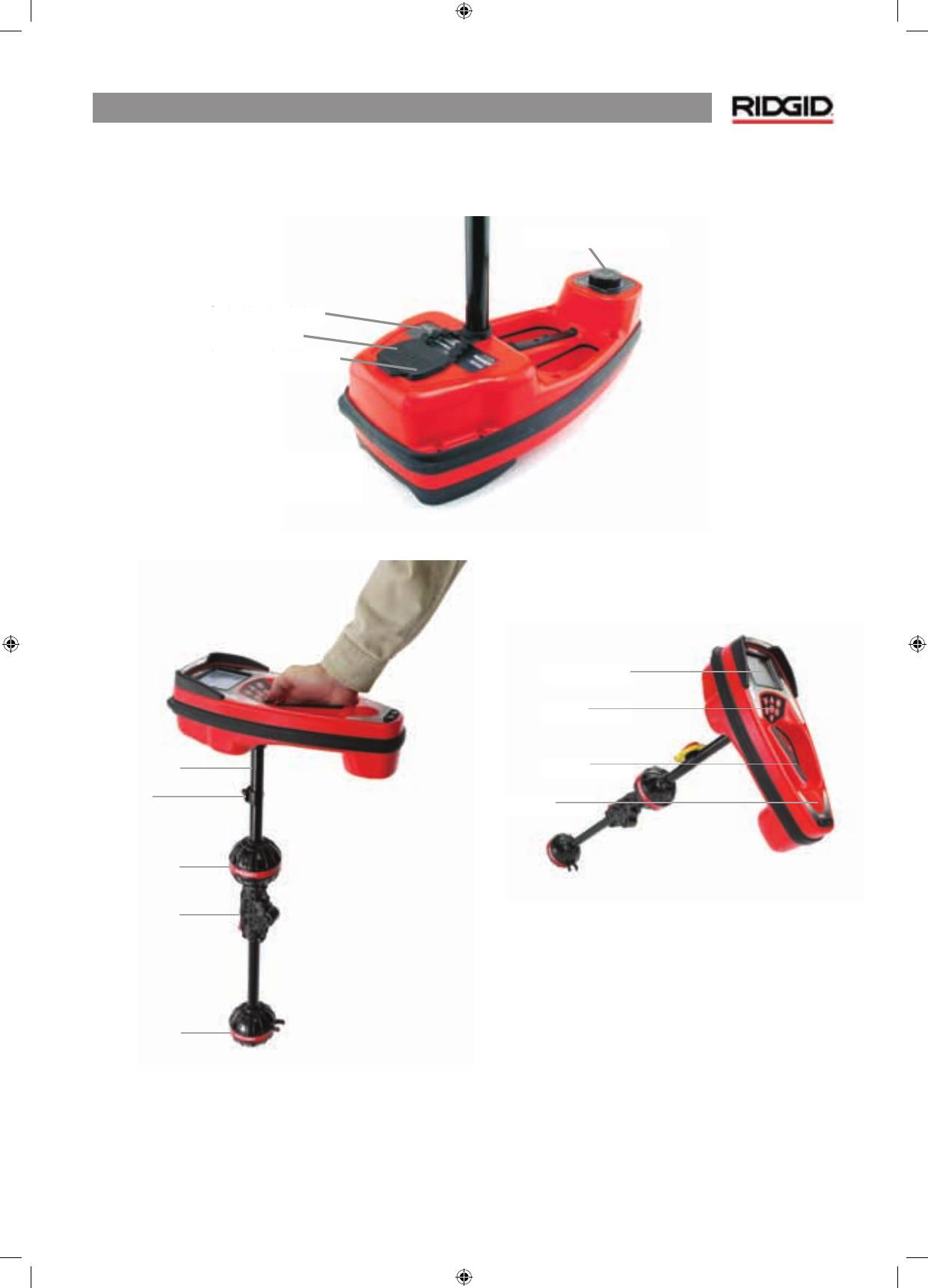
NaviTrack® II Components
Figure 1: NaviTrack® II Components
Display Screen
Keypad
Handle
Speaker
Antenna Mast
Markers
Upper Antenna
Node
Folding Joint
Lower Antenna
Node
Battery Compartment
Serial Label
USB Connector
Serial Port Connector
NaviTrack® II
4
Introduction to the NaviTrack® II
Getting Started
Installing/Changing Batteries
To install batteries into the NaviTrack® II turn the unit over to
access the battery compartment. Turn the knob on the battery
cover counter clockwise. Pull straight up on the knob to remove
the door. Insert the batteries as shown on the inside decal and
make sure they drop to full contact.
Fit the door into the case and turn the knob clockwise while
lightly pressing down to close. The battery cover can be
installed in either orientation.
Figure 2: Battery Case
When the NaviTrack® II is powered on, it takes a few seconds
to check the batteries. Until then the battery level will show
as “empty”.
WARNING!
Do not allow debris or moisture into battery
compartment. Debris or moisture in the battery compartment
may short the battery contacts, leading to rapid discharge of
the batteries, which could result in electrolyte leakage or risk
of fire.
Folding Mast
To begin operation, unfold the antenna mast and lock the
folding joint into place. When locating is complete, press the
red release lever to fold the antenna mast for storage.
WARNING:
Do not snap or whip the NaviTrack® II to open or
close it. Open it and close it by hand only.
NOTE:
Avoid dragging the lower antenna node on the ground
while locating with the NaviTrack® II. It may cause signal noise
which will interfere with results, and may eventually damage
the antenna.
Figure 3: Folding Antenna Mast and Release Button
NaviTrack® II
5
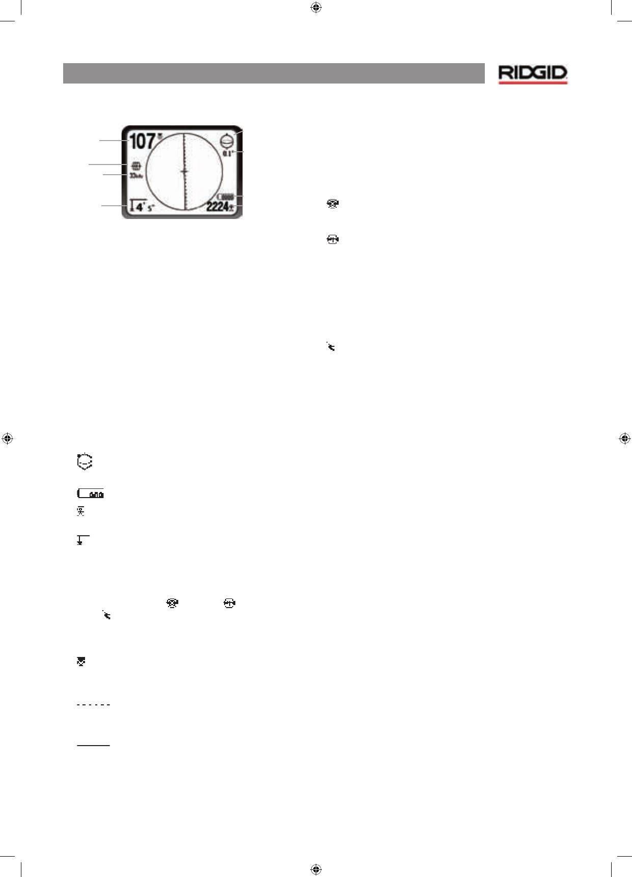
Display Screen
Figure 4: Elements of the Display Screen
(Default, Line Trace Mode)
Features
A beginning locator and a sophisticated and experienced
locator can use the NaviTrack® II with equal ease. While the
NaviTrack® II offers advanced features which make the most
complex locate easier, many of its features can be turned off
or hidden to make the display simpler and clearer when doing
basic locating in uncomplicated situations.
Basic Features
The “basic features” of the NaviTrack® II are turned on by default.
They can be customized easily to suit the user’s requirements.
The default display screen as shipped will show the following
features:
•
Angle –
Angle toward the field’s center graphically
displayed; numeric value displayed below the graphic.
•
Battery Level –
Indicates level of battery power.
•
Signal Strength –
Strength of signal as sensed by the
lower Omnidirectional antenna.
•
Depth/Distance –
Displays depth when receiver is
touching the ground directly over signal source. Displays
distance when the antenna mast is pointed at signal
source in some other manner. Default setting displays feet/
inches.
•
Mode –
Icon for Sonde
, Line Trace,
, or Power (Passive
Trace) mode.
•
Frequency –
Shows current frequency setting in Hertz or
kiloHertz.
•
Proximity Signal –
Numerical indication showing how
close the signal source is to the locator. Displays from 1 to
999.
•
Upper Antenna Signal Trace –
line shows the
apparent direction of the field as detected at the upper
antenna.
•
Lower Antenna Signal Trace –
line shows the
apparent direction of the field as detected at the lower
antenna.
•
+ Map Center –
shows where the receiver/locator is relative
to the map display.
Default Frequencies
The frequencies that are activated in the default setting can
be cycled through when locating simply by pressing the
Frequency button. Default frequencies include:
Sonde
•
512 Hz
Line Trace
•
128 Hz
•
1 kHz
•
8 kHz
•
33 kHz
•
262 kHz
Power (Passive Trace)
•
50/60 Hz
The use of these features is described in the Line Tracing, Sonde
Locating and Passive Tracing sections.
Mode Frequency
Depth/Distance
2D Horizontal Field Angle Indicator
Numeric Horizontal Angle Indicator
Battery Level
Seignal Strength
Proximity
Signal
Frequency
Depth/
Distance
2D Horizontal Field
Angle Indicator
Numeric Horizontal
Angle Indicator
Battery Level
Signal Strength
Mode
NaviTrack® II
6
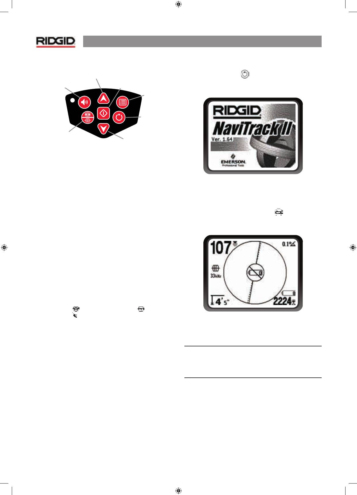
Keypad
•
Power On/Off –
Turns NaviTrack® II on. Turns the NaviTrack® II
off after a 3-second countdown. The countdown can be
interrupted before shutdown by pressing any key.
•
Up and Down Arrows –
Used for locating choices during
menu selection; used for setting the Volume Control when the
sound key has been pressed.
•
Select Key –
Used to make a choice during Menu selection; in
normal operation, used to force a depth reading and re-center
audio tone.
•
Menu Key –
Used to display a “tree” of choices including
frequency selections, display element choices, brightness and
contrast, and restoring default settings. In a menu, will move
up one level.
•
Volume Key –
Used to raise or lower the volume setting; will
cycle the volume through high to zero. Pressing the volume
opens the Volume control panel if it is closed, and closes it if
it is open. Volume can also be raised and lowered using the
arrow keys when in the Volume control panel.
•
Frequency Key –
Used to set the working frequency of the
NaviTrack® II from the set of activated frequencies. The list of
frequencies which have been activated can be modified via
the menu. Frequencies are grouped into
four sets
: Sonde
Frequencies (
), Line Trace Frequencies (
), and Power
Frequencies ( ).
Operation Time
Using alkaline cells, typical operation time is from about 12 to
24 hours depending on sound volume and how often the
backlight is on. Other factors that affect the operation time
will include chemistry of the battery (many of the new high
performance batteries, such as the “Duracell® ULTRA” last
10%-20% longer than conventional alkaline cells under high
demand applications). Operation at lower temperatures will
also reduce battery life.
The NaviTrack® II display can also show random symbols when
the battery power is too low to drive the internal logic circuits
correctly. This is remedied by simply putting fresh batteries
into the unit.
To preserve battery life the NaviTrack® II will automatically shut
down after 1 hour of no key presses. Simply turn the unit on
to resume use.
Starting Up
After pressing the Power
key on the keypad, the RIDGID®
logo displays, and the software version number will appear in
the lower left corner.
Figure 5: Start-up Screen
Low Battery Warning
When the battery gets low, a battery icon
will appear in the
map area on the screen. This indicates that the batteries need
to be changed and that the unit will soon shut down.
Figure 6: Low-Battery Warning
Just before complete shut down there will be a non-
interruptible power down sequence.
NOTE
: Voltage on rechargeable batteries may sometimes drop
so quickly that the unit will just shut down. The unit will turn
off and restart. Just replace the batteries and turn the unit
back on.
Volume Controle Key
Up Key
Menu Navigation
Select Key
Menu Item Select
Menu Key
Power ON/OFF Key
Down Key
Menu Navigation
Frequency Key
Volume Controle Key
Up Key
Menu Navigation
Frequency Key
Select Key
Menu Item Select
Menu Key
Power ON/
OFF Key
Down Key
NaviTrack® II
7
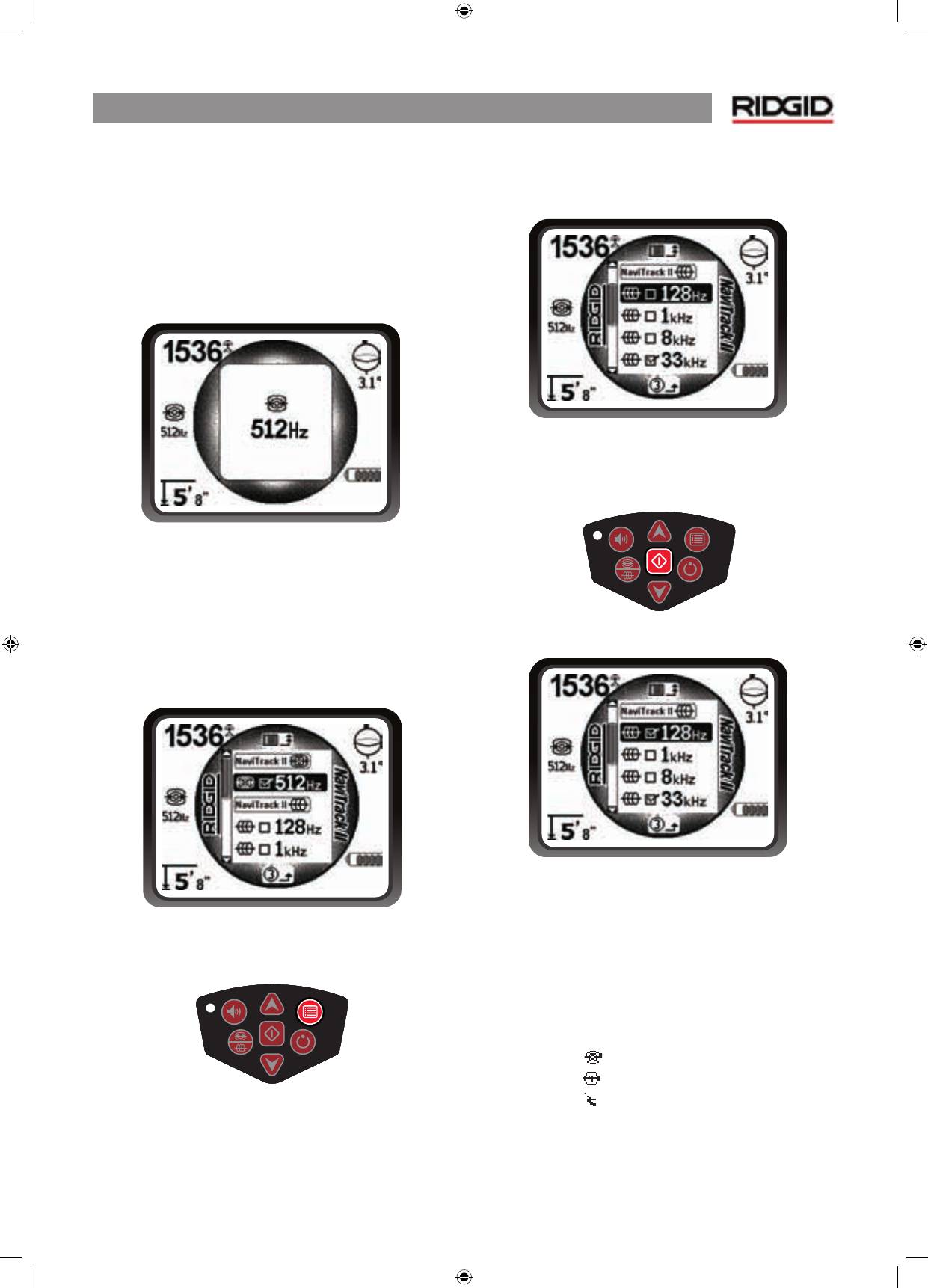
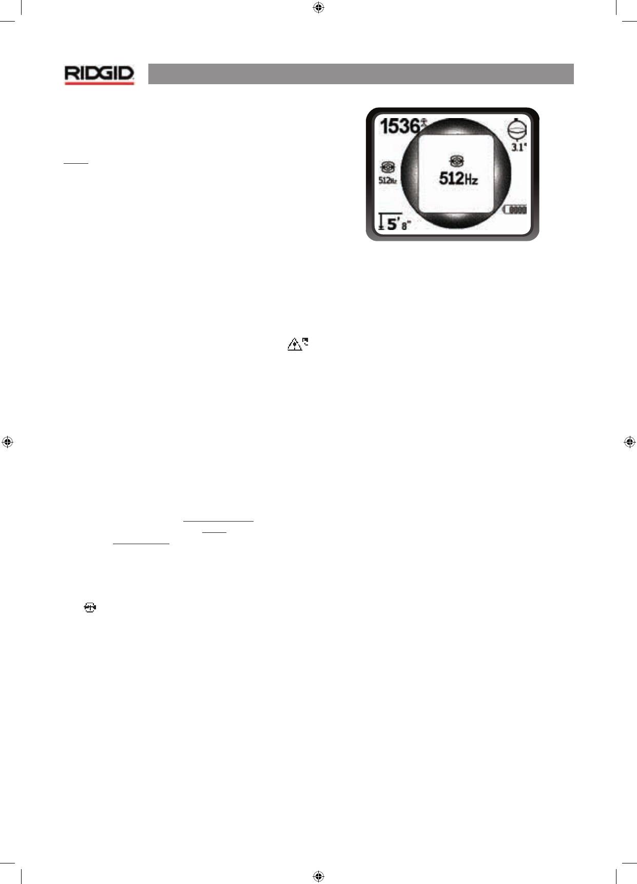
Set Up
Once the NaviTrack® II is up and running the next step is to set
up the frequencies needed that match the transmitter, sonde,
or line to be located.
Frequencies that are already turned on appear in sequence by
pressing the Frequency key. (For example, the default Sonde
frequency of 512 Hz is available by pressing the Frequency
key.)
Figure 7: Sonde Frequency Selected With Frequency Key
Note that the usual Sonde Frequency, 512 Hz, is turned on
by default.
Other frequencies can be added to the set of activated, turned-
on frequencies so they will be available using the Frequency
Key.
Each is turned on for use by selecting it from a list in the Main
Menu.
Figure 8: Main Menu
1. Push the menu key:
Figure 9: Menu Key
2. Using the up and down arrows, highlight the frequencies
desired. In this example, the operator is activating a
128 Hz frequency.
Figure 10: Highlighting a Desired Frequency (128 Hz)
3. Press the select key (shown below) to check the box for
each frequency intended for use.
Figure 11: Select Key
Figure 12: Desired Frequency Checked
4. Frequencies that have been selected for use will show a
check in the box next to them. (Menu key exits to operating
display.)
The Main Menu lists all available
activated
frequencies. Different
frequencies can be turned on or off for different jobs from the
activated frequencies list, by checking them or unchecking
them using the Select key.
Frequencies are grouped by category:
Sonde
Line Trace
Power
NaviTrack® II
8
Adding Frequencies
Additional
frequencies can be added to the Main Menu list
of available frequencies by going to the
Frequency Select
Submenu
and selecting the desired mode.
To activate frequencies go down to the Frequency Selection
submenu, and highlight the category of the
desired frequency.
Figure 13: Selecting a Frequency Category
Then use the arrow keys to scroll through the available
frequencies. Highlight the desired frequency to add it to the
Main Menu list.
Figure 14: Highlighting a Frequency To Activate
Checking a frequency (using the Select key) will include it in
the activated frequencies on the Main Menu. Unchecking it
will hide it from the active frequency set.
Figure 15: Selecting a Frequency to Activate
Checking or unchecking a frequency, selects or deselects it
to be included on the Main Menu. To switch frequencies from
among those that are activated, press the Menu key and go
down the Main Menu to the desired frequency; then return
to the map display. The NaviTrack® II will show the chosen
frequency and its icon on the left of the screen.
Pressing the Menu key when done will return to the map
display, one menu level at a time.
Selected frequencies in the activated set can be switched while
the NaviTrack® II is in use, by pressing the Frequency button.
The NaviTrack® II will cycle through the set of active frequencies
from low to high and repeat. Unchecking a frequency in the
Main Menu will deselect it even though it is “activated”, and it
will then not appear when pressing the Frequency button.
NOTE
: If a frequency seems to have “disappeared” first look to
make sure it is in the Main Menu activated frequencies list. If it
is, select it by checking it using the Select key. If not, go to the
Frequency Selection menu and the appropriate sub-category
and activate it there by checking it, using the Select key. Make
sure it is “checked” at
both menu levels
for it to appear in the
current working set of frequencies.
Other Options
The Main Menu also includes options for changing the
display units (feet or meters), adjusting the backlight (on/
off/automatic) and adjusting the contrast setting for the LCD.
Selecting from the Main Menu by pressing the Select key will
display the options or a submenu.

NaviTrack® II
9
Sounds of the NaviTrack® II
In normal use the sound level is driven by the proximity to the
target. The closer to the target, the higher the sound level will
be. A rising tone indicates increasing signal. If the sound level
reaches its highest point, it will “re-scale” to a medium level
and continue signaling from the new starting point.
If desired, force the sound to re-center at a medium level by
pressing the Select key during operation.
NaviTrack® II
10
Sonde Locating
The NaviTrack® II can be used to locate the signal of a sonde
(transmitter) in a pipe (must be a non-metallic pipe !!), so that
its location can be identified above ground. Sondes can be
placed at a problem point in the pipe using a camera push rod
or cable. They can also be flushed down the pipe.
IMPORTANT!
–
Signal strength is the key factor in
determining the sonde’s location
. To ensure an accurate
locate, take care to maximize the signal strength prior to
marking an area for excavation.
The following assumes that the sonde is in a horizontal pipe,
the ground is approximately level and the NaviTrack® II is
held with the antenna mast vertical.
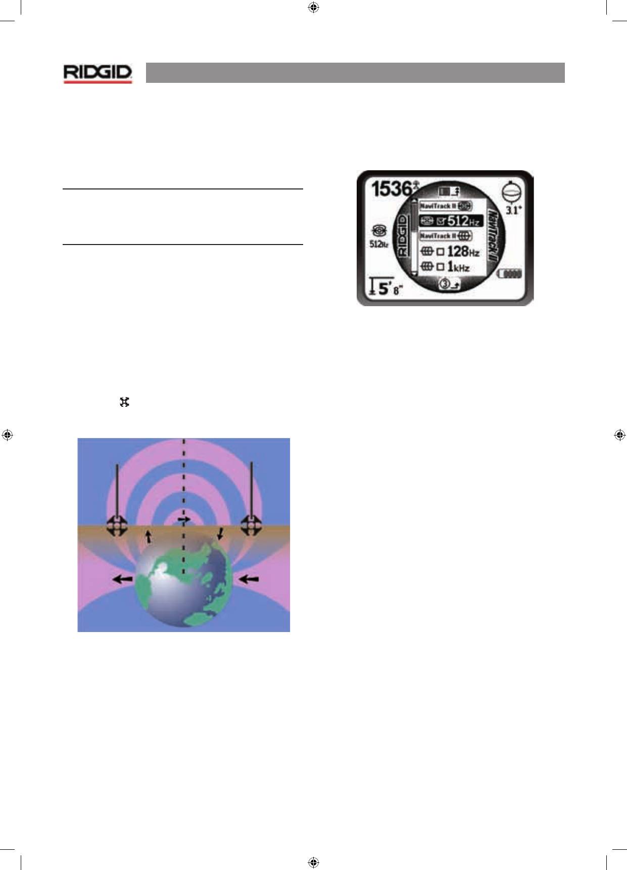
The field of a sonde is different in form than the circular field
around a long conductor such as a pipe or cable. It is more like
the field around a bar-magnet, with a north pole and a south
pole. Because of differences in the two kinds of fields, the
display in Sonde mode shows signal strength in the upper left
corner, rather than Proximity signal.
In the sonde’s field, the NaviTrack® II will detect the points
at either end where the field lines curve down toward the
vertical, and it will mark these points on the map display with
a “pole” icon ( ). The NaviTrack® II will also show a line at
90 degrees to the sonde, centered between the poles, known
as the “equator”, much like the equator on a map of the Earth.
Figure 16: The Earth’s Dipole Field
To get an idea of a dipole field, imagine the sonde underground
with a field similar to the Earth’s magnetic field, as shown in
Figure 16.
When locating a sonde set up the locate in the following
manner:
•
Activate the sonde before putting it in the line.
Select the same frequency on the NaviTrack® II and
make sure it is receiving the signal.
Figure 17: Sonde Frequencies On the Main Menu
•
After the sonde has been sent into the pipe, go to the
suspected sonde location. If the direction of the pipe is
unknown, push the sonde a shorter distance into the
line (~4-5 m from the access is a good starting point).
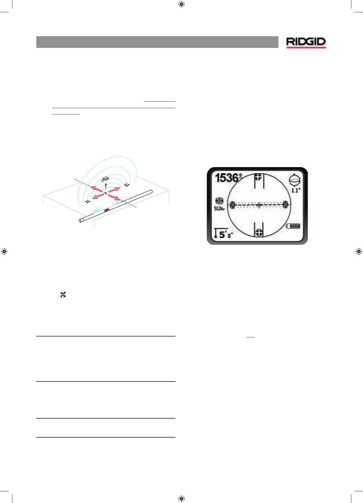
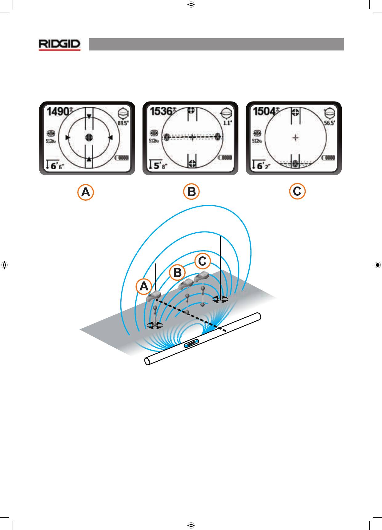
Location Methods
There are three major parts to locating a sonde. The first
step is to find
direction
. The second part is homing in on (or
“localizing”) the
area
of the sonde. The third is completing
the locate by
pinpointing
its location.
Step 1: Finding the Direction
1. Hold the NaviTrack® II so the antenna mast is pointing
outward. Sweep the antenna mast in the suspected
direction of the sonde while observing the signal
strength and listening to the sound. The signal will
be highest when the antenna mast is pointing in the
direction of the sonde.
2. Lower NaviTrack® II to its normal operating position
(antenna mast vertical) and walk in the direction of the
sonde. Approaching the sonde, the signal strength will
increase and the audio tone will rise in pitch. Use the
signal strength and the sound to maximize the signal.
Ground
Ground
Pole
Equator
Pole
Pole
Pole
Equa
tor
NaviTrack® II
11
Step 2: Localize the Area
1. Maximize the signal strength. When it appears to
be at its highest point, place the NaviTrack® II close
to the ground over the high-signal point. Note the
Signal Strength and move away from the high point
in
all
directions. Move the NaviTrack® II far enough in
all directions to verify that the Signal Strength drops
significantly on all sides. Mark the point of highest
signal strength with a yellow marker.
2. If while “getting closer” a stable equator appears on the
screen it can be followed toward an increasing signal
strength to localize the sonde.
Figure 18: Poles and Equator of a Sonde
3. If while “getting closer” a pole appears first, localize the
sonde by centering in on the pole icon (the icon may
move closer in to the sonde as the receiver approaches
it).
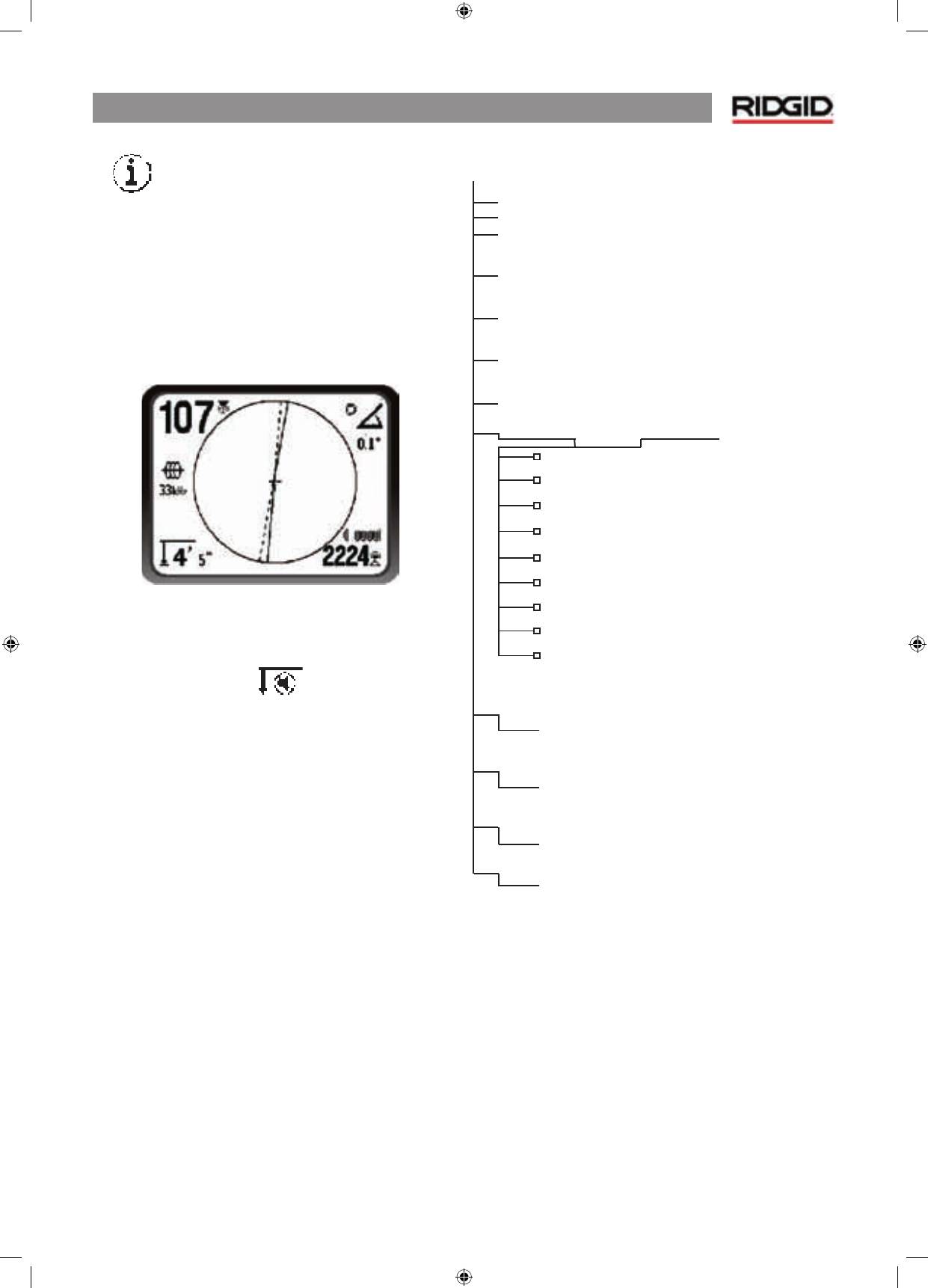
Step 3: Pinpoint the Sonde
The poles should appear on either side of the maximum
signal point, an equal distance on either side if the sonde
is level. If they are not visible on the screen at the point of
maximum signal strength, move from the maximum point
perpendicular to the dotted line (equator) until one appears.
Center the locator over the pole.
The dotted line represents the equator of the sonde.
If the sonde is not tilted, the equator will intersect the
sonde at maximum signal strength and minimum depth.
NOTE:
being on the equator does not mean that the locator is
over the sonde. Always verify the locate by maximizing signal
strength and marking both poles.
1. Mark the first pole location found with a red triangular
marker. After centering on the pole, a double-line
indicator will appear representing the direction of the
sonde
When the locator gets close to a pole, a focusing ring will
appear centered on the pole, allowing precision centering.
2. The second pole will be a similar distance from the
sonde location in the opposite direction. Locate it in the
same manner and mark it with a red triangular marker.
3. If the sonde is level, the three markers should be aligned
and the red pole markers should be at similar distances
from the yellow sonde marker. If they are not, a tilted
sonde may be indicated.
Verify
. It is important to verify the sonde’s location by
crosschecking the receiver’s information.
4. Double-check. Move the NaviTrack® II away from
the maximum signal strength, to make sure that the
signal drops off on all sides. Make sure to move the
unit far enough to see a significant signal drop in each
direction.
Figure 19: Sonde Locate: Equator
5. Double-check the two pole locations.
6. Notice that the depth reading at the maximum signal
strength location is reasonable and consistent. If it
seems far too deep or too shallow, recheck that there is
an actual
maximum
signal strength at that location.
7. Notice that the poles and the point of highest signal
strength line up.
IMPORTANT! – Remember that being on the Equator does
NOT mean one is over the sonde.
Note that seeing two poles
aligned on the display is not a substitute for centering over
each pole separately and marking their locations as described
above.
NaviTrack® II
12
If the poles are not in evidence, extend the search. The object is
a maximum signal point which falls off in all directions.
For best accuracy the NaviTrack® II should be level.
The
antenna mast must be vertical when marking the Poles and
Equator, or their locations will be less accurate.
Figure 20: Screen Display In Different Locations (Sonde)
On the pole
On the equator
Approaching the 2nd pole
NaviTrack® II
13
Operating Tips for Locating a Sonde
Figure 21: Locating a Sonde
Tilted Sondes
If the sonde is tilted, one Pole will move closer to the sonde
and the other farther away so that the sonde location no
longer lies midway between the two poles. The signal strength
of the nearer Pole becomes much higher than that of the more
distant Pole.
As the sonde tilts to vertical, one Pole moves to a point directly
above the sonde and this Pole will also correspond to the point
of maximum signal strength. The other Pole will not be seen.
Therefore even if the sonde is vertical, as it could be if it fell into
a break in the line it can still be located.
What is seen on the screen when the sonde is
vertical
is a single
Pole at the point of maximum signal strength.
It is important to realize that a severely tilted sonde can cause
the pole locations and the equator to appear out of true
because of the angle of the sonde; but the signal strength will
still guide to the best location for the sonde.
Figure 22: Tilted Sonde, Poles and Equator
Note the right-hand pole is closer to the equator, due to tilt.
Floating Sondes
Some sondes are designed to be flushed or to drift down a
pipe pushed by water flow. Because these sondes swing much
more freely than a torpedo-shaped sonde in a pipe, they can
be oriented any which way.
This means the equator may be distorted by tilting, and the
location of the poles may vary. The only guarantee of having
located a floating sonde is maximizing the signal strength and
double-checking that the signal falls away on every side of the
maximum signal location.
Normal
Maximum Signal Strength
Tilted
Normal
Max.
Tilted
NaviTrack® II
14
Measuring Depth
The NaviTrack® II measures depth by comparing the strength
of the signal at the lower antenna to the upper antenna.
Depth is measured correctly when the mast is held vertical and
the bottom antenna is touching the ground directly above the
signal source.
1. To measure depth, place the locator on the ground,
directly above the sonde or the line.
2. Depth will be shown in the lower left-hand corner of
the NaviTrack® II’s display screen.
3. A depth reading can be forced by pressing the select
key during a locate.
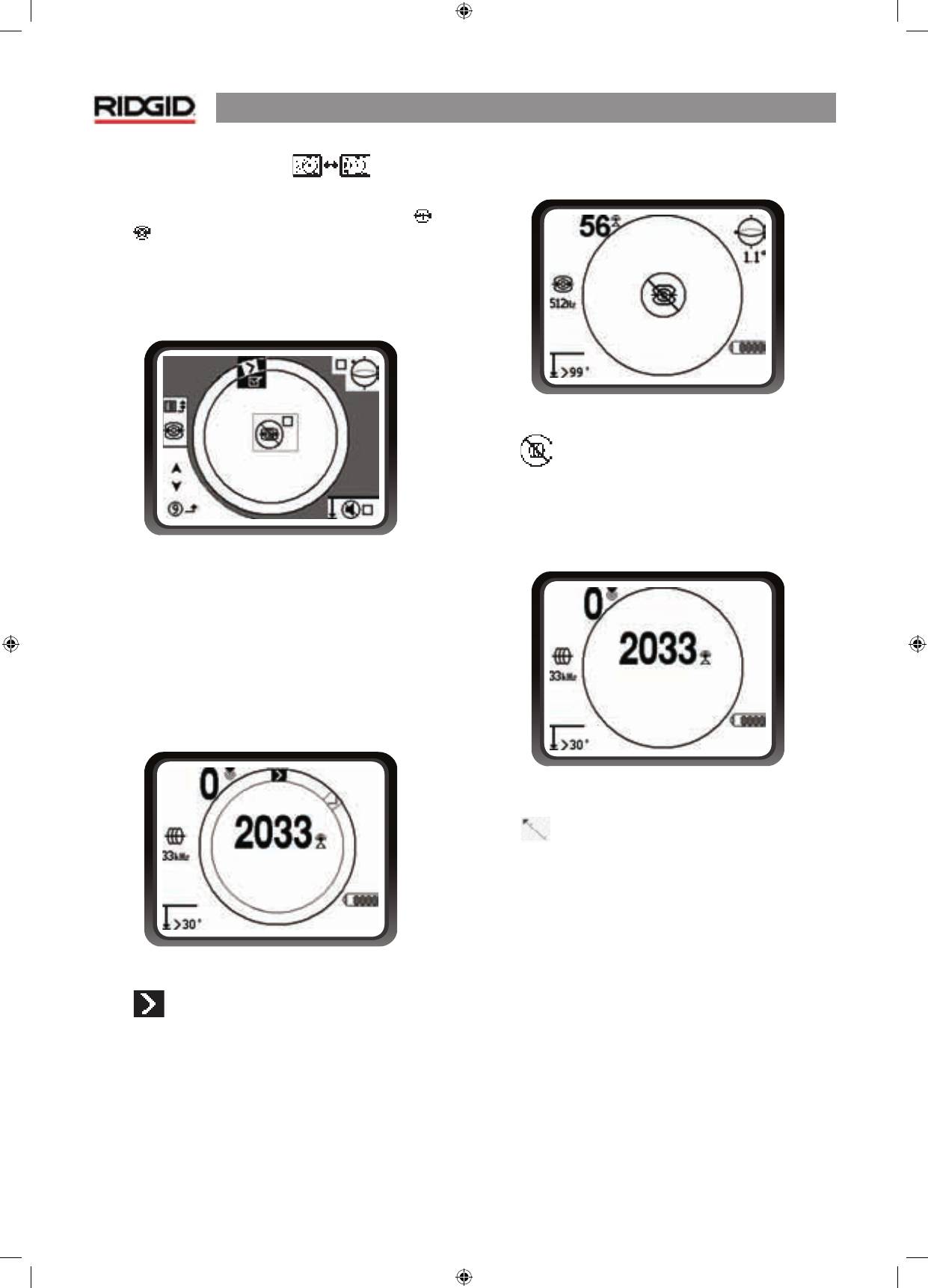
Clipping
Occasionally the signal strength will be strong enough that the
receiver will be unable to process the whole signal, a condition
known as “clipping”. When this occurs a warning symbol
will appear on the screen. It means that the signal is particularly
strong. When locating a line, if clipping persists, remedy it by
reducing the strength of the current from the transmitter.
Clipping is unlikely to occur in Sonde locating, and would
indicate the receiver was very close to the sonde.
Active Line Tracing
In active line tracing, underground lines (lines that can “carry”
an electromagnetic signal (thus plastic pipes cannot be located
this way)) are energized with a line transmitter. This active
signal is then traced using the NaviTrack® II. A line transmitter is
different from a sonde in that it is used for tracing an energized
line, rather than acting as a target for a locate as a sonde is. Line
transmitters energize lines by direct connection with clips, by
directly inducing a signal using a clamp, or by inducing the
signal using inductive coils built in to the transmitter.
1. Energize the line according to the manufacturer’s
instructions. Select the transmitter frequency.
Set the frequency used on the NaviTrack® II to the same
frequency used on the transmitter. Be sure it has a line trace
icon
. Push the main menu button to return to the map
display.
Figure 23: Line Trace Frequency Chosen
With the Frequency Button
2. Observe the Proximity Signal to ensure the NaviTrack® II
is picking up the transmitted signal. The signal should
peak over the line and drop off on either side.
3. When tracing, the direction the pipe or cable is running
will be shown on the screen with 2 lines, one solid and
one dashed. The dashed line is the signal as seen by the
upper antenna node and the solid line is the signal as
seen by the lower one. The angle indicator will be near
zero if over the center of the field.
4. Use the Proximity Number, Signal Strength, and Signal
Trace Lines to guide the line trace. These three pieces
of information are generated from discrete signal
characteristics to help the locator discern the quality
of the locate. An
undistorted
signal emitted from a
line is strongest directly over that line. By maximizing
the Proximity Signal, and centering the Signal Trace
Lines on the screen the confidence in a “good” locate
is high. Confirm a locate by testing whether the depth
reading is stable and reasonable. One way to test for
the consistency of the depth reading by raising the
NaviTrack® II a known distance (say, 35 cm exactly) and
observing whether the depth indicator increases by
the same amount. Small variation is acceptable, but if
the depth does not change, or changes drastically, it is
an indication of a “distorted” field, or very low current
on the line. (As always, the only way to be completely
certain of the location of a utility is through visual
inspection by exposing the utility.)
NaviTrack® II
15
Figure 24: High Probability Locate
CAUTION:
Care should be taken to watch for signal interference
that may give inaccurate readings. Depth readings should be
taken as estimates and
actual depths should be verified by
exposing the line before digging
.
Using a Line Transmitter
In active Line Tracing, the NaviTrack® II works in conjunction
with an active line transmitter unit. There are three ways to
connect a line transmitter.
Direct Connection
The best way to connect a transmitter is usually by directly
connecting it (metal to metal) to one end of a target utility
pipe, trace-wire or cable, and sending the transmitted current
directly along the target.
Clamp Connection
Where direct connection is not possible, it is often possible to
fix an inductive clamp connector around the target conductor,
which energizes it inductively. To effectively induce a signal
using a clamp, the line must be metallic, and must have both
ends of the line grounded. (Signal can not be induced onto
a line in one direction unless current is able to flow in both
directions.)
Inductive Transmission
The transmitter can be used in an inductive mode
without
a
direct connection. This requires making sure the transmitter is
directly over a known segment of the target line and activating
the transmitter’s “inductive mode” which will illuminate the
line at a selected frequency.
NOTE:
Refer to the manual provided with the transmitter
being used to ensure it is properly connected and grounded,
and set to the correct frequency.
Each of these methods has advantages depending on the
situation. Direct connection is usually most reliable in that the
signal is being applied directly to a known line; but situations
exist where induction may be the only option, or may work
better.
Passive Line Tracing
In passive mode the NaviTrack® II senses alternating current, or
AC fields generated by wires already carrying current, without
a transmitter being attached. Buried power lines typically do
not emit any traceable signal unless power is flowing in the
wires. For example streetlights that are turned off are hard
to trace passively. Due to coupling (either through induction
or through capacitance), all metallic lines in an area can be
energized passively. Because of this it is possible to locate lines
passively but it can be difficult to identify
which
line the locator
is tracing.
WARNING:
In passive locating or when signals are extremely
weak, the depth will generally read too DEEP and the actual
buried depth may be MUCH shallower.
1. Select a Passive AC Trace Frequency with the passive
line trace icon.
Figure 25: 60 Hz Passive Trace Frequency
2. The NaviTrack® II has two passive AC tracing frequency
settings. They are 50 Hz, and 60 Hz. They are identified
with the power icon. The 50 Hz and 60 Hz respond to a
harmonic of commonly used AC frequencies. European
installations are typically 50 Hz.
When passive tracing, it is important to remember that T’s,
curves, other conductors in the vicinity, and nearby masses of
metal
can
add distortion to the field requiring closer scrutiny
of the data to determine the path of the target.
In general, passive tracing is the least effective option.

NaviTrack® II
16
Operating Tips for Line Tracing
•
The NaviTrack® II quickly identifies distorted fields. If the
lines are not centered on the map, and Proximity Signal
or signal strength is maximized, distortion is creating a
complex rather than circular field. To improve the tracing
circuit:
a) Try changing the frequency used to a lower one.
b) Move the ground stake position away from the line
being traced.
c) Make sure that the line is not commonly bonded to
another utility. Undo common bonds only if safe to
do so.
d) Move the transmitter to a different point on the line
and try doing the trace in the opposite direct (B to A
instead of A to B).
•
If the lines will not center or if they move across the screen
erratically, then the NaviTrack® II may not be receiving a
clear signal. The depth and the Proximity Signal may also
scroll up and down under these circumstances.
a) Check the transmitter to be sure that it is operating
and well grounded.
b) Test the circuit by pointing the lower antenna at
either transmitter lead.
c) Check that the NaviTrack® II and transmitter are
operating on the same frequency.
d) Try different frequencies, starting with the lowest,
until the line can be picked up dependably.
e) Re-locate the ground connection for a better circuit.
Ensure there is enough contact (ground stake is
sufficiently deep) especially in dryer soils.
•
While tracing, the signal should maximize, and the depth
minimize, at the same place where the lines center on the
display. If this is not the case, the utility may be changing
direction or other coupled signals may be present.
•
Higher frequencies bleed over more but may be needed to
jump breaks in tracer wires or go over insulating couplers.
If the line is ungrounded at the far end, higher frequencies
may be the only means to make the line visible (see Figure
37).
•
When using the transmitter inductively, be sure to begin
the locate about 10 m feet away to avoid “direct coupling”,
also known as air coupling or “air lock”. This occurs when
the NaviTrack® II picks up the signal from the transmitter
directly through the air and not from the line to be traced.
To test for air coupling, point the NaviTrack® II directly
at the transmitter; if signal strength increases, then the
transmitter is too close to the receiver to trace accurately.
•
While tracing, the mapping display operates best under
the following conditions:
1. The Line is level
2. The NaviTrack® II Locator is above the target utility
level
3. The NaviTrack® II antenna mast is held approximately
vertical
If these conditions are not met, pay close attention to
maximizing Proximity Signal and signal strength.
In general, if the NaviTrack® II is used in a zone over the target
line within a sweep area of about two “depths” of the line, the
map will be useful and accurate. Be aware of this when using
the map if the target or line is very shallow. The useful search
area for the map can be small if the line is extremely shallow.
Measuring Depth
The NaviTrack® II measures depth by comparing the strength
of the signal at the lower antenna to the upper antenna.
Depth is measured correctly in an undistorted field when the
bottom antenna is touching the ground directly above the
signal source.
1. To measure depth, place the locator on the ground,
directly above the sonde or the line.
2. Depth will be shown in the lower left hand corner. A
depth reading can be forced by pressing the Select
key.
Clipping
Occasionally the signal strength will be strong enough that the
receiver will be unable to process the whole signal, a condition
known as “clipping”. When this occurs a warning symbol will
appear on the screen. It means that the signal is particularly
strong. If clipping persists, it can be remedied by reducing the
strength of the current from the transmitter.
NOTE:
In Line Trace mode, pressing the Select key will force a
depth reading and will force the angle indicator to change to
current. If sound is turned on, it will also re-center the audio
tone.
NaviTrack® II
17
Menus and Settings
Pressing the Menu key brings up a series of choices which let
the individual operator configure the NaviTrack® II.
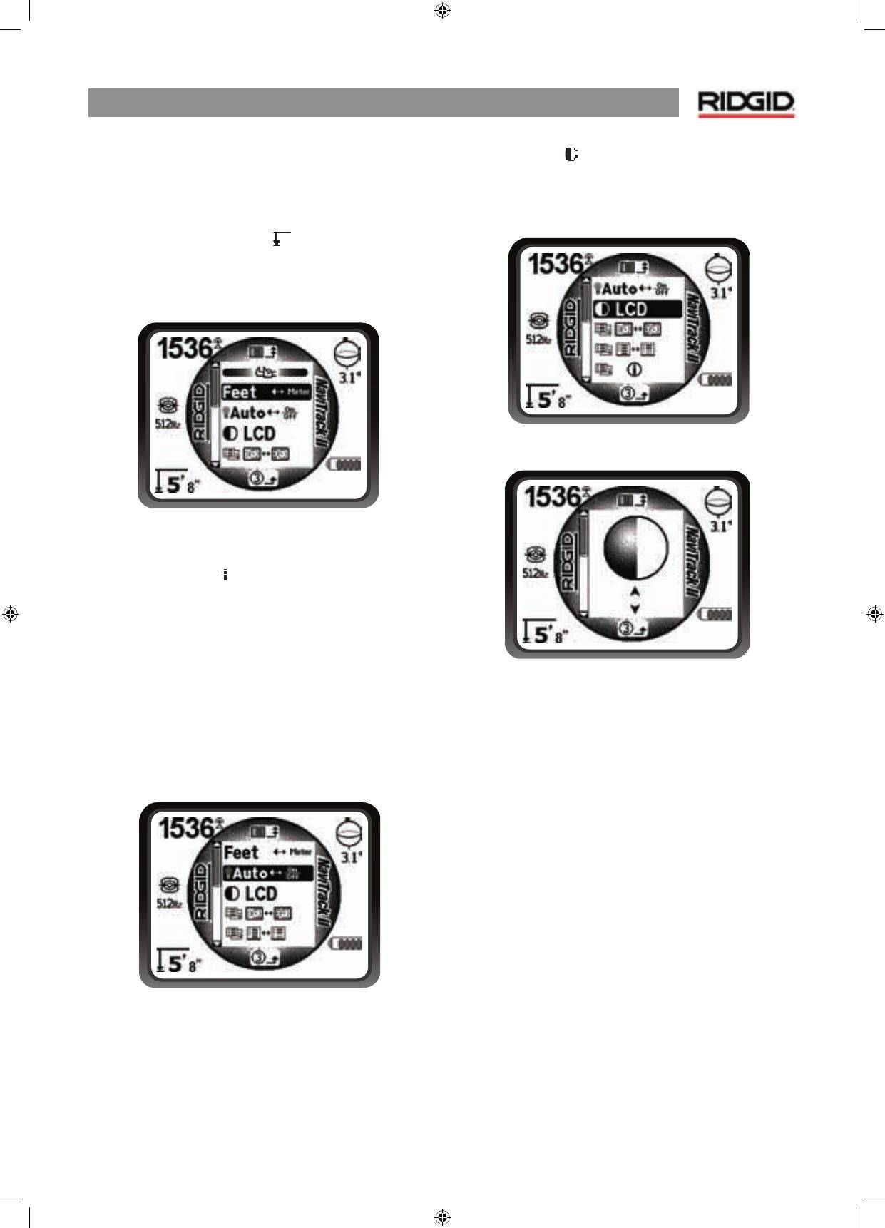
Change of Depth Units
The NaviTrack® II can display depth in either Feet or Meters. To
change these settings highlight the Units selection in the Menu
and press the select key to toggle between feet or meters.
Figure 26: Selecting Units (Feet/Meters)
Auto Back Light
A light detector built into the upper left corner of the keypad
senses low light levels. The backlight can be forced on by
blocking the light to this sensor.
The automatic LCD backlight is factory set to only turn on
under fairly dark conditions. This is to conserve battery power.
As the batteries near depletion, the backlight will appear dim.
Near the end of battery life, the backlight operates at a very
low level to conserve battery power.
To set the backlight to be always off, highlight the light bulb
icon in the tools section of the menu and press the select key
to toggle it between Auto, always ON and always OFF.
Figure 27: Setting Backlight Mode (On/Off/Auto)
LCD Contrast
When this is selected by pressing the select key the contrast
can be adjusted. Use the up and down arrows to make the
screen lighter or darker.
Figure 28: Contrast Setting Option
Figure 29: Increasing/Decreasing Contrast
NaviTrack® II
18
Display Elements Menu
Selecting the icon representing two small display screens will
bring up the Display Selection Menu for either Trace
or
Sonde
mode. This control is used to turn screen elements
on and off. The NaviTrack® II is shipped with some of the
elements turned off for simplicity. To turn an element on or
off, press the up or down arrow to
highlight
the selection then
use the
select key
to
check
or
uncheck
the box. Checked display
elements are turned on for the selected mode
Figure 30: Screen Elements (Sonde Mode)
Optional Features
Advanced features of the NaviTrack® II can be turned on by
using the Menu key to show the menu tree. Select the Display
Elements selection menu (for display elements – described on
page 18) or the Frequency Selection menu (to activate other
frequencies – described on page 8).
Optional Features
include:
Figure 31: Racetrack with Watermark and Pointer
•
Watermark
The watermark is a marker which appears in the outer ring of
the display. It is a graphic representation of the highest signal
strength reached. It is “chased” by a solid pointer which shows
the current signal strength. If the signal strength pointer
goes higher than the watermark, the watermark moves up
accordingly to show the new highest level graphically.
It is turned off by default but can be turned on in the Display
Elements selection menu.
Figure 32: “No-Signal” Display
•
No-Signal Icon
When the NaviTrack® II is not receiving any meaningful signal
on the selected frequency it will display the mode sign with
a line through it, indicating no signal is being detected. This
reduces the confusion of trying to interpret the random noise
that some locators display in the absence of a signal.
Figure 33: Signal Strength Centered
•
Center Signal Strength Option
Turning the option on in the Menu Selection screen will force
the number representing signal strength to be displayed
in the center of the display area
anytime when no Proximity
Signal is available
. This may occur when signal is weak. When a
Proximity Signal again becomes available, the signal strength
number returns to the lower right corner of the screen as usual.
(Line Trace Mode only.)
NaviTrack® II
19
•
Information Screen
The information screen appears at the bottom of the menus
choices list. Pressing the Select button displays information
about the locator, including software version, serial number of
the receiver, and its calibration date.
Pressing Select a second
time will display the Restore Factory Defaults option.
•
Restore Factory Defaults
This option is turned on by selecting the checked box (√). If
the “X” option is chosen, no change from current settings will
be made.
Figure 34: Defaults Restored (Line Trace Mode)
Pressing the Menu key without changing either checkbox will
exit the option and leave things as they were.
•
Sound Muting > 99’
This option enables the automatic muting of the sound when
the depth is greater than 99 feet. If it is unchecked, the sound
will not mute automatically.
Menu Tree
The following graphic shows the options and controls built into
the NaviTrack® II menus. Pressing the menu key from the active
screen moves the display to the top of the menu tree. Move
through the choices using the arrow keys. Pressing the Select
key when any choice is highlighted will show that submenu.
Pressing the menu key within a sub-menu will move up one
level. Checkboxes are turned on and off by pressing the Select
key.
Activated Frequencies
Sonde
Line Trace
Power (Passive Trace)
Units of Measure
Feet/Meters
Backlight Options
On/Off/Auto
LCD Contrast
Increase/Decrease
Display Elements Select
(Check On/Off)
Trace Mode
Sonde Mode
Watermark
No-Signal Indicator
Sound Signals
Center Signal Strength*
Signal Strength
Angle Indicator
Mute > 99’
Tracing Lines*
*=Line Tracing Display Only
Frequency Select
(Check On/Off)
Sonde
16 Hz, 512 Hz, 640 Hz, 850 Hz, 8 kHz,
16 kHz, 33 kHz
Line trace
128 Hz, 1 kHz, 8 kHz, 33 kHz, 200 kHz,
262 kHz
Power
50 Hz, 60 Hz
Information Menu
Restore Default Settings
(Check Yes/No)
