Ridgid SLIDING LADDER RACK 250: инструкция
Раздел: Техника
Тип:
Инструкция к Ridgid SLIDING LADDER RACK 250
RID 085-210-024.10
RIDGE TOOL COMPANY
GB p. 1
DE p. 7
NL p. 13
IT p. 19
PT p. 25
SV p. 31
DA p. 37
FI p. 43
HR p. 49
RO p. 55
RU p. 61
TU p. 67
p. 73
SLIDING
LADDER
RACK
MODEL 250
Tools For The Professional
TM
SLV
cover_manual_SLR250.indd 3
30/04/2009 15:31:07

Tools For The Professional
TM
SLIDING LADDER RACK
Ridge Tool Company
1
GB
Operating Instructions
SLIDING LADDER RACK
MODEL 250
www.ridgid.eu/jobsitestorage
TOOLS REQUIRED
• Electric Drill
• 5/16” Hex Driver Bit
• Phillips Screw Driver
• Ruler
• 7/16” Wrench
• 7/16” Deep Well Socket
• Ratchet Wrench
• Lithium Grease
PARTS LIST
To reduce the risk of serious personal injury, read and follow all instructions and warnings before installing or using this
product.
RIDGID recommends the Model 250 sliding ladder rack be installed in service or delivery vans equipped with a bulkhead.
A bulkhead divider between cargo and driver/passenger compartment reduces the likelihood material will come forward and
cause personal injury during a vehicle accident.
WARNING
–ATTENTION–
NOTE: This product is only intended for use inside a van, enclosed trailer or truck with metal cap.
(1) Cord guide
(24)1/4” Flat Washer
(1) Front cradle
(2) Connecting bracket
(4) Strut channel nut
(1) Pan head machine
screw, 1/4 x 20 x 7/8
(1) Inside side catch
(3) Mounting bracket
(2) Stop plate
(2) Shock cord
(1) Outside side catch
(1)Vinyl cap
(1) 1.25 OD Washer
(4) Lock washer
(1) Fixed catch
(8) 1/4 x 14 self drilling
screw
(4) Hex head cap screw,
1/4 x 20 x 1
(1) Adjustable mount
(17)Carriage bolt,
1/4 x 20 x 3/4
(1) Rear mounting bracket
(20) Nylon lock nut, 1/4 x 20
(1) Fixed mount
(1) Safety cable assy.
(2) Carriage bolt,
1/4 x 20 x 1-1/2
(1) Adjustable arm
(3) Rail
sliding_eng.indd 1
27/04/2009 11:04:01
Tools For The Professional
TM
SLIDING LADDER RACK
Ridge Tool Company
2
To reduce the risk of serious personal injury from the ladder falling or becoming a projectile during hard braking or a vehicle
accident:
• Read and follow all instructions and warnings before installing or using this product.
• The sliding ladder rack should only be used for transporting ladders. Never modify or use the sliding ladder rack for any
other purpose.
• Rack must be installed per instructions.
• Only mount the sliding ladder rack in a van, enclosed trailer, or metal truck cap.
• Maximum ladder weight should not exceed 36Kg
• When using power tools, follow tool manufacturer’s warnings and instructions.
• Protect your eyes. Wear safety goggles.
• Never install the sliding ladder rack system inside passenger compartments.
• Check for electrical wiring in areas where holes are to be drilled. Consult the vehicle’s shop manual for wiring paths.
INSTALLATION INSTRUCTIONS
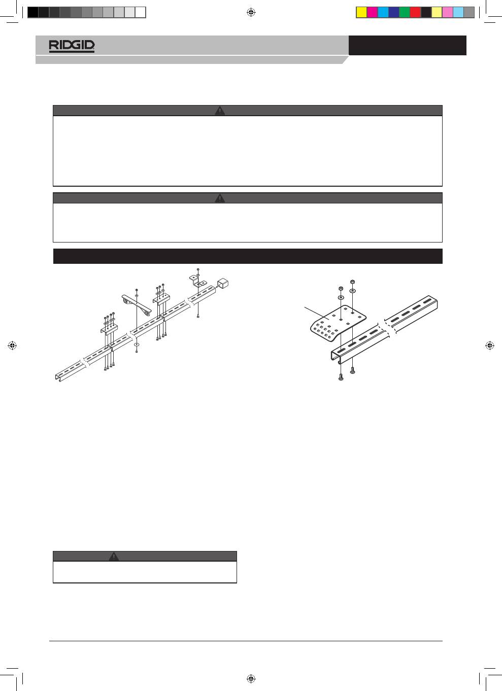
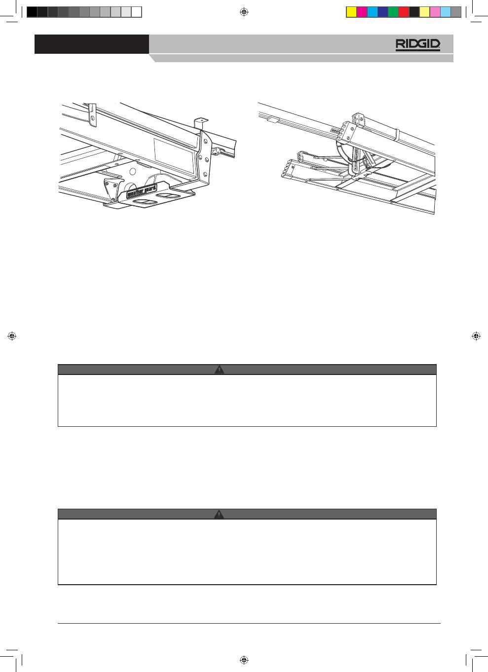
Step 1: RAIL ASSEMBLY INSTALLATION
Using connecting brackets (2), connect rail sections (3) us-
ing eight 1/4-20 x 3/4” carriage bolts, 1/4” flat washers and
1/4-20 nylon lock nuts.
NOTE:
The installation instructions below are written for the
installation of this product to the roof ribs of a van or truck
cap. This rack can be mounted to the side wall of a trailer if
desired, using the same steps described below.
NOTE:
Depending on the size and type of your vehicle, the
rail assembly may need to be cut to length for proper instal-
lation, Measure the distance inside the van, and cut the
assembled rail to the correct length.
Determine the rail mounting location inside vehicle (center,
offcenter, side). Measure the first three van rib locations
from the rear of the van, starting from the upper inside of
the rear door jamb, and measuring forward. Record those
dimensions.
• Rail assembly must be attached to all three roof ribs for
proper installation.
Fasten the rear mounting bracket to the rear of the rail
assembly(end opposite cut end) using two 1/4-20 x 3/4”
carriage bolts, 1/4” flat washers and 1/4-20 nylon lock nuts.
See Figure 1a.
From the rear of the rear mounting bracket, mark the rail
assembly at the recorded rib locations. Fasten a mounting
bracket just tight enough to be adjusted by hand, centered
at each mark, using one 1/4-20 x 3/4” carriage bolt, 1/4” flat
washer and 1/4-20 nylon lock nut each.
Place the rail assembly in the vehicle in position. Determine
whether the rear mounting bracket needs to be modified.
It may be offset to the rail assembly or have a portion of it
removed or the angle of the flange changed to meet the
door jamb flush, if necessary. Adjust the mounting bracket
locations on the rail assembly if necessary, to insure that
the mounting brackets can be properly fastened to the roof
ribs.
Remove the rail assembly from the roof ribs, and tighten the
mounting brackets securely.
Place the rail assembly back in position, and fasten it to the
roof ribs and rear door jamb with two 1/4-14 x 3/4” self drill-
ing screws and 1/4” flat washers per bracket.
Fasten the cord guide approximately 30” in from the rear of
the rail assembly, using a 1/4-20 x 7/8” pan head machine
screw, 1-1/4” OD washer, 1/4” flat washer and 1/4-20 nylon
lock nut. Adjust the 30” dimension for obstructions if neces-
sary.
Figure 1
Figure 1a
Rear
Mounting
Bracket
WARNING
WARNING
CAUTION
sliding_eng.indd 2
27/04/2009 11:04:03
Tools For The Professional
TM
SLIDING LADDER RACK
Ridge Tool Company
3
Figure 2
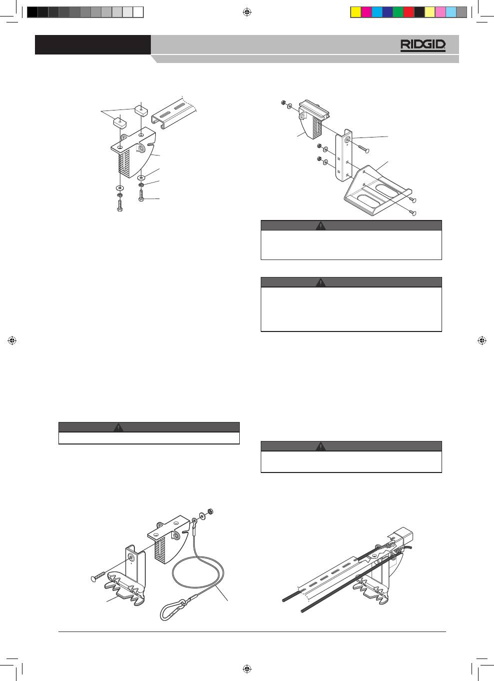
Step 2: INSTALLING FIXED MOUNT
Measure from the foot of the ladder to the bottom rung.
From the back of the rail assembly measure the same dis-
tance and mark the rail. This will be the approximate loca-
tion of the fixed mount. Install the fixed mount with grooves
facing the front of the vehicle. Allow for position adjustment
using fasteners shown in Figure 2.
Step 3: INSTALLING SLIDING MOUNT
Insert the sliding mount into the rail assembly with the
grooved portion facing the rear of the vehicle. Install the
vinyl cap over the cut end of the rail assembly.
Step 4: FRONT CRADLE ASSEMBLY
INSTALLATION
NOTE:
If installing this sliding ladder rack to the side wall of
a trailer, proceed to Step 10 for the side catch assembly.
Using two 1/4-20 x 7/8” carriage bolts, 1/4” flat washers,
and 1/4- 20 nylon lock nuts, affix front cradle to exten-
sion arm. Attach to sliding mount. With one 1/4-20 x 1-1/2”
carriage bolt, 1/4” flat washer, and 1/4-20 nylon lock nut,
adjust the depth of the cradle to fit the height of your ladder.
Tighten carriage bolt completely (Figure 3).
Do not over tighten fasteners.
Step 5: FIXED CATCH
Using one 1/4-20 x 1-1/2” carriage bolt, 1/4” flat washer, and
1/4- 20 nylon lock nut, affix the fixed catch and safety cable
to the fixed mount allowing for adjusting the depth to fit the
bottom rung of the ladder. Tighten carriage bolt completely
(Figure 4).
Step 6: ADJUSTING MOUNTING POSITIONS
Place ladder onto the front cradle and slide forward to the
stowed position. Place the bottom rung of the ladder onto
the fixed catch. This will be the final position of the fixed
catch assembly. Gently remove the ladder so as not to
move the fixed catch and finish securing the fixed catch as-
sembly in place.
Step 7: SHOCK CORD INSTALLATION
• Slide the shock cords through the adjustable mount shock
cord holes. Make sure the hog ring is at the back of the unit.
Next slide the cords through the shock cord guide holes,
and then through the fixed mount shock cord holes.
• Safety cable must be attached per instructions for lad-
der to be properly secured to rack and vehicle.
• Do not over tighten fasteners.
• Fixed Catch assembly is not completely secured at this
point. When placing ladder into position it could fall.
• Do not allow anyone directly underneath or to the side
of ladder during this installation step, except to help
with mounting.
• Elastic cords can snap back and strike your eye. Do not
over stretch. Keep your body and face clear.
• Place ladder onto rack and slide forward while holding the
shock cord. When the ladder is in the stowed position, firmly
pull the shock cord and slide it into the holding slot on the
back of the fixed mount (see figure 5).
CAUTION
WARNING
CAUTION
WARNING
Fixed Mount
1/4” Flat Washer
Lock Washer
1/4-20 x 1
Hex Head
Cap Screw
Strut
Channel
Nut
Adjustable
mount
Adjustable Arm
Front Cradle
Figure 3
Figure 4
Fixed Catch
Figure 5
Safety Cable
sliding_eng.indd 3
27/04/2009 11:04:05
Tools For The Professional
TM
SLIDING LADDER RACK
Ridge Tool Company
4
Elastic cords can snap back and strike your eye. Do Not overstretch. Keep your body and face clear.
Front Stop Plate must be installed to prevent the sliding catch from dislodging during hard braking or in a vehicle accident.
Before loading ladder into rack:
1. RIDGID recommends the Model 250 sliding ladder rack be installed in service or delivery vans equipped with a bulk head.
A bulkhead divider between cargo and driver/passenger compartment reduces the likelihood material will come forward
and cause personal injury during a vehicle accident.
2. The sliding ladder rack is designed to be loaded from the back of a cargo van or pickup truck with a metal cap.
3. Before loading a ladder, make sure the elastic cords and the stop bracket are installed and positioned correctly. See
Installation steps 7 & 8 on pages 3 & 4. If a different size ladder is to be loaded then the stop bracket and the elastic cords
must be adjusted or the ladder will fall from the rack.
4. Inspect the parts of the ladder rack before using. If any part is broken, bent or damaged in any way do not use rack. See
Maintenance section for replacement parts.
USAGE INSTRUCTIONS
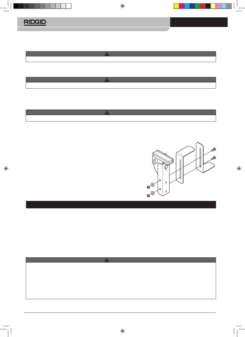
Figure 6
WARNING
Elastic cords must be properly adjusted. Failure to adjust cord tension for length of ladder may allow ladder to fall.
Step 8: INSTALL FORWARD AND REAR STOPS
Recommended position of the forward stop is approximately 1” in front of the sliding mount in the stowed position. The posi-
tion of the stop should allow just enough travel to slide the ladder forward to place the bottom rung onto the adjustable catch
as well as ladder removal.
Step 9: RAIL LUBRICATION
Apply a generous amount of lithium grease to the inside of
the rail allowing for smooth travel of the sliding front cradle.
Optional Installation
Step 10: SIDE MOUNTING INSTALLATION
INSTRUCTIONS
(ONLY)
Install side catch brackets to adjustable mount with two 1/4-
20 x 7/8” carriage bolts, 1/4” flat washers, and 1/4-20 nylon
lock nuts as shown in Figure 6. Install rail assembly to side
of enclosed trailer.
• Inspect the sliding ladder rack before each use. Do not use rack if it is damaged or deteriorated in any way.
• Do not place shorter ladder in rack adjusted for longer ladder. Always adjust stop plate and elastic cords for length of lad-
der being loaded.
• Incorrect loading or unloading of the sliding ladder rack could allow ladder to fall and cause serious personal injury or prop-
erty damage.
• Never operate the rack with persons seated below or near the rack and ladder.
• Be careful when loading ladder into the sliding ladder rack if standing on slick or icy ground.
• Do not load or unload ladder when vehicle is moving.
• Make sure to have enough tension on the shock cord to securely hold the ladder in place. Tie a double knot into the end of
the shock cord at this point, and insert the cords in the slots in the fixed mount. Tuck the excess into the back of the fixed
mount (see figure 5).
WARNING
WARNING
Rear stop should be placed far enough forward to limit travel of the sliding mount allowing you to pull the ladder easily off of the
front cradle assembly without hitting the fixed catch.
WARNING
sliding_eng.indd 4
27/04/2009 11:04:05
Tools For The Professional
TM
SLIDING LADDER RACK
Ridge Tool Company
5
• Always attach safety cable around ladder step. Safety cable reduces the risk of the ladder coming free during a vehicle
accident.
• Inspect ladder before each use. Ladder can be damaged from road shock and vehicle vibration. Bouncing and side-to-side
motion may cause wear and weaken the ladder. Using a damaged ladder could lead to structural collapse and result in
serious injury or death.
• Keep hands clear of area where ladder engages rack.
Loading ladder into rack:
1. Ensure the ladder is clean and dry.
2. Open van’s rear doors or truck hatch to access rack.
3. Pull on elastic cords to move the sliding catch toward the
rear.
4. Position the ladder with the step side down (non-step
side up).
5. Lift the top of the ladder and place it in the front cradle.
See Figure 7.
6. Moving to the foot of the ladder, lift and push forward,
causing the sliding mount to move forward and the elastic
cords to become tight. Stop if elastic cords become tan-
gled with the ladder. Straighten cords and continue.
7. With a firm two hand grip on the ladder, push and lift so
that the undersize of the bottom step is aligned with the
face of the fixed catch. Ease your forward pressure and
Un-Loading ladder from rack:
1. To un-load ladder from rack, reverse the loading process
above while following these steps.
2. Make sure you have secure footing and a clear path
behind your vehicle to walk the ladder out.
3. Check that the ladder has not shifted in the rack and is
still securely held by the fixed catch.
4. Remove the safety cable from around the step.
Figure 7
Figure 8
allow the elastic cords to push the step against the fixed
catch.
Note:
The face of the fixed catch is designed to engage a
variety of step designs. If the bottom step on your
ladder does not engage securely with the fixed catch
try to reposition the step. If you need to adjust the
fixed catch’s mounting position, refer to the installa-
tion instructions in Step 4 on page 3.
8. Ensure the ladder is properly engaged with the fixed
catch.
9. Loop the safety cable around the bottom step and clip
it back on itself as shown in Figure 8. Always attach the
safety cable around a step. Other parts of the ladder may
not be strong enough to hold the ladder in a vehicle ac-
cident.
5. Push the ladder forward and then down to disengage the
step from the face of the fixed catch. Be prepared for the
push-back from the elastic cords.
6.Walk away from the vehicle until the top of the ladder has
slid to near the fixed catch.
7. For long or heavy ladders, set the bottom of the ladder
down to the ground and then move up the side of the lad-
der to a position and lift the top from the front cradle.
• Do Not operate vehicle without the safety cable in place. Safety cable reduces the risk of the ladder from ladder falling or
becoming a projectile during a vehicle accident.
• Never allow persons to sit below or near the stowed ladder while vehicle is in motion.
• If your vehicle is involved in an accident or you have applied your brakes excessively hard, STOP immediately and check
to make sure ladder has not moved out of position in rack.
• Travel over rough terrain or a hard, jarring bump may cause the ladder to fall. Additional securing of the ladder may be
required to insure the ladder stays in place.
WARNING
WARNING
sliding_eng.indd 5
27/04/2009 11:04:06
Tools For The Professional
TM
SLIDING LADDER RACK
Ridge Tool Company
6
Conduct periodic inspection of your sliding ladder rack for wear and tear, damage or loose parts. Repair or replace as neces-
sary.
Apply a generous amount of lithium grease to the inside of the rail allowing for smooth travel of the sliding front cradle.
Check the elastic cords for damage and wear. If cloth covering is frayed, cord could break unexpectedly. Replace the cords
before using the rack.
Check the safety cable for damage or breakage. Look for broken strands. If found replace cable before using the rack.
GENERAL MAINTENANCE
• To reduce the risk of personal injury:
• Do Not use ladder rack with missing or damaged parts.
• Inspect elastic cords for wear. If cloth covering is frayed, cord could break unexpectedly. Do not use rack.
• Maintain grease on rail.
Any modification or unintended use of this product shall immediately void all manufacturers warranties. Manufacturer dis-
claims all liability for injuries to persons or property resulting from any modification to, or unintended use of this product.
LIMITED WARRANTY
This LIMITED WARRANTY is made by RIDGID on-site storage equipment, 420 E. Terra. Cotta Ave., Crystal Lake, Illinois to the original
retail purchaser of RIDGID
®
products.
RIDGID on -site storage equipment WARRANTS THAT RIDGID PRODUCTS WILL BE FREE FROM DEFECTS IN MATERIAL AND
WORKMANSHIP FOR A PERIOD OF THREE (3) YEARS FROM DATE OF PURCHASE BY THE ORIGINAL RETAIL PURCHASER.
THIS WARRANTY IS SPECIFIC TO THIS STORAGE EQUIPMENT. WARRANTIES FOR OTHER RIDGID PRODUCTS MAY VARY
If, before the expiration of the Warranty period, purchaser discovers that the RIDGID product fails to fulfill the Warranty, purchaser
shall contact RIDGID on-site storage equipment to make arrangements for an inspection of the product. If RIDGID determines a defect
exists, RIDGID shall, at its option and expense, repair or replace any defective part. All Warranty repairs shall be made by an authorized
RIDGID product dealer or RIDGID approved service company.
This Warranty shall not apply if the RIDGID product has been subjected to misuse, abnormal service or handling, improper
maintenance, or alterations made by anyone other than RIDGID Product dealer or a RIDGID approved service company.
THE WARRANTY PRINTED ABOVE IS THE ONLY WARRANTY APPLICABLE TO THIS PURCHASE. ALL OTHER WARRANTIES,
EXPRESS OR IMPLIED, INCLUDING BUT NOT LIMITED TO THE IMPLIED WARRANTIES OF MERCHANTABILITY AND FITNESS
FOR A PARTICULAR PURPOSE ARE HEREBY DISCLAIMED.
RIDGID on -site storage e quipment SHALL NOT BE LIABLE FOR ANY INCIDENTAL OR CONSEQUENTIAL DAMAGES ARISING
OUT OF ANY BREACH OF THIS WARRANTY NOR SHALL THE DAMAGES EXCEED THE RETURN AMOUNT OF THE PURCHASE
PRICE PAID BY THE ORIGINAL PURCHASER
This Warranty is in lieu of all Warranties express or implied. The terms of this Warranty shall not be modified by any party, their succors
and assigns. This Warranty gives you specific legal rights, and you may also have other rights which vary from state to state.
WARNING
–NOTICE–
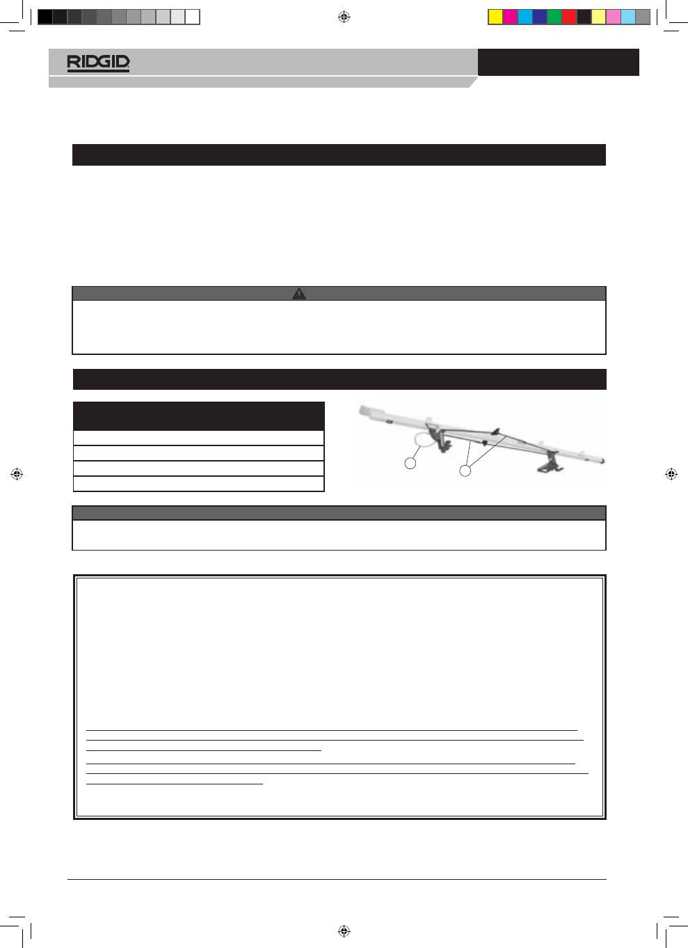
SERVICE PARTS
2
1
FOR REPLACEMENT PARTS GO TO
www.ridgid.eu/jobsitestorage
ITEM NO.
PART NO.
DESCRIPTION
1
34213
Safety Cable
2
34208
Shock Cord (1 pair)
3
34218
Bolt Kit (not shown)
Ridge Tool Europe, Interleuvenlaan 50, B-3001 Leuven www.ridgid.eu
sliding_eng.indd 6
27/04/2009 11:04:06
