Ridgid 3814 (E): инструкция
Раздел: Электроинструменты
Тип:
Инструкция к Ridgid 3814 (E)
RIDGE TOOL COMPANY
3801 (E)
3802 (E)
3811 (E)
3812 (E)
3813 (E)
3814 (E)
Tools For The Professional
TM
GB p. 1
DE p. 6
FR p. 11
NL p. 17
IT p. 22
ES p. 27
PT p. 32
SV p. 38
DA p. 43
NO p. 48
FI p. 53
HR p. 58
PL p. 63
RO p. 68
CZ p. 73
HU p. 78
GR p. 84
RU p. 90
3801(E), 3802(E), 3811(E), 3812(E), 3813(E), 3814(E)
Ridge Tool Company
1
WARNING! Read these instructions
and the accompanying safety booklet
carefully before using this equipment. If
you are uncertain about any aspect of using this
tool, contact your RIDGID distributor for more
information.
Failure to understand and follow all instructions
may result in electric shock,
fi
re, and/or serious
personal injury.
SAVE THESE INSTRUCTIONS!
Assembling
1. a. 1 1/4”, 2” and 3” machines.
Place the bending frame with its supports on the
fl
oor and slip the ring
over the front of the pump cylinder.
Place the U-bracket through the holes in the ring block of the bending
frame. The pump cylinder and pipe bending frame are now
fi
xed in the
correct position.
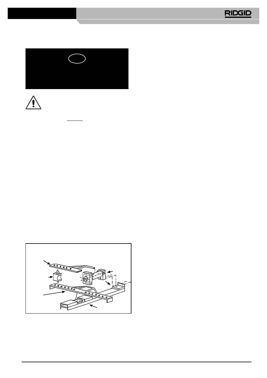
1. b. 4” machine.
- Place the base beam on the
fl
oor.
- Place the lower wing on the base beam.
- Place the bending-pump on the base beam, hook the lower wing
into the pump and secure the pump at the rear with two M10 bolts.
- Place the corner-supports and where applicable the bending-
former that you will be using, on the lower wing.
- Place the upper wing on the corner-supports and hook it into the
pump.
- Insert
the
fi
xing-pins through the wings and the corner-supports.
ASSEMBLING OF THE 4” MACHINE
4” pump
Upper wing
Corner support
with
fi
xing pins
Lower wing
Base beam
2. Mount a bending former according to the diameter of the pipe to be
bent, on the ram top. The corner supports must be placed between, or
on the bending frame. They are fastened by means of the
fi
xing-pins.
The holes in the frame allow the corner supports to be adjusted to the
desired outside diameters. The holes are marked accordingly. Ensure
that the
fi
xing pins for corner supports are properly
fi
tted through both
wings or through the bending frame to prevent damage.
Bending
1. The
fi
lling cap is pierced for air release. Whenever the bending
machine is transported this
fi
lling cap must be tightly closed, but
released a little when in use.
2. Before bending, the pipe should be slightly greased. The pipe is then
slipped between the corner supports and bending former. The relief
spindle must be locked tightly. By moving the handle up and down the
pump is put into operation. The ram moves out and the pipe is bent.
The bending operation should be continued until the desired curve
is reached but not further than the bending former curve. It should
be remembered that the pipe will spring back a little according to the
quality of the pipe. This must be established by experience.
3. As soon as the pipe reaches its required shape, loosen the relief
spindle and the ram withdraws automatically. Disconnect one of the
corner supports and the pipe can be removed. The models equipped
with an open frame have the advantage that the bent tube can
removed easier, especially long pieces of tubes with several bends,
thus saving a lot of time.
4. If a bend has been bent too far this can be corrected by means of
the straightener. The ram must be reversed and the tube turned over
against the corner supports. The straightener is placed on the ram top
and the bend can now be pushed back to its desired shape. On the
1 1/4” bending machine a bend of 90° cannot normally be corrected.
This also applies to the 3” machine for 2 1/2” and 3”, for the 4”
machine for 3” and 4” pipes.
5. For 3” and 4” model only.
When bending 2 1/2”, 3” and 4” pipes an extension piston should be
applied to the ram when the tube has been bent past 75°. The stroke
of the ram is not enough to bend a 90° bend in one operation.
6. 1 1/4”, 2”, 3”, 4” electro-hydraulic pipe bending machines.
The electro-hydraulic pipe bending machines are equipped with a
single phase 115 V, 220 V, AC or 380 V 3 phase motor. The motor has
a special safety switch. Once the motor is running the movement of
the ram is controlled by means of a relief spindle which can be either
opened or closed. The motor does not have to be switched off. The
machine also features a pressure safety valve. This is factory set so
that heavy wall pipe (steam pipe) can be bent without any problem.
The pressure safety valve is situated in the pump housing and can
only be set by means of a manometer.
Bending of Hairpin Shapes of 180°
For this, additional accessories are required which can be delivered on
request.
Assembling
1. See under assembling bending machine.
2. The bending former (180°) according to the size of the pipe to be
bent, is placed on the ram. Next, the plates (spare frames) with 3 rolls
(diabolos) are adjusted between or in the frame. The
fi
xing-pins for
corner supports must be put in the holes 1 1/4” through the center
lock; the removable diabolo must be removed and the pipe to be bent
run through. The pipe must now touch the center diabolo with one side
and the 180° bending form with the other side. Bending can now be
started.
Bending
1. See under bending.
2. If the bending is more than 90°, the ram must be reversed, by
releasing the relief spindle. Adjust the removable diabolos and bend
up to 180°. To remove the bent pipe, see Bending.
GB
3801(E), 3802(E), 3811(E), 3812(E), 3813(E), 3814(E)
Operating Instructions

3801(E), 3802(E), 3811(E), 3812(E), 3813(E), 3814(E)
Ridge Tool Company
2
Maintenance
The bender is delivered with a
fi
lled oil container. However, the oil level
must be checked regularly as otherwise the stroke of the ram will become
too short. Oil must always be level with the bottom of the
fi
lling cap. If oil
needs to be added, use only hydraulic oil.
Caution
1. Ensure that corner supports are always adjusted symmetrically in
the holes, according to the size of the pipe to be bent. If not placed
properly, the ram instead of the pipe may be bent and the machine
badly damaged.
2. Also take care that
fi
xing-pins for corner supports are properly
fi
tted
through the holes in the upper and under wing of the bending frame,
and all the way through on the open bending frame.
3. The ram must not be moved out beyond the groove mark.
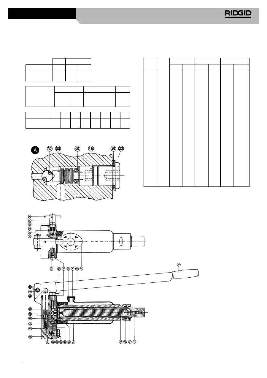
Faults which may occur and how they can be corrected
Numbers in brackets refer to electric machines.
FAULT
POSSIBLE CAUSE
HOW TO CORRECT
1. The ram (33) will not move out far enough.
a. The
fi
lling cap (37) is not loosened suf
fi
ciently.
b. The oil container is not
fi
lled suf
fi
ciently.
c. Air vent in
fi
lling cap (37) is blocked.
a. Release
fi
lling cap (37) about 1 or 1 1/2 turns.
When removing the machine take care that
fi
lling cap is closed tightly.
b. Re
fi
ll oil container until oil is level with bottom of
fi
lling cap. The ram should not be pumped out
beyond the groove mark on the ram.
c. Clean air vent hole.
2. The ram (33) will not move out at all.
a. The relief spindle (7) is not tightened enough.
b. Ball (32) does not lock when pressing; possibly
dirt on ball cone.
c. Filter (42) and/or oil supply channel is clogged.
a. Tighten the relief spindle.
b1. Clean ball cone under ball (32).
Eventuallly knock ball on cone for tighter
fi
t.
b2. Please contact supplier.
c. Remove lock pin (34). Clean
fi
lter and oil supply
channel.
3. The ram (33) gives only little or no pressure at
all.
a. Relief spindle (7) is not tightened.
b. Because of dirt between cone and ball (32) of
the relief spindle (7), oil is leaking back to the
oil container.
c. Ball (32) does not lock because of dirty cone.
d. Packing under safety screw for pull spring (27)
is leaking.
e. Packing (40) is leaking.
f. Press packing (46) is leaking.
a. Tighten the relief spindle.
b. Detach relief spindle (7), ring nut (8), packing
(9) and bottom rings (10). Clean cone for ball
(31). See 2b1. (If necessary contact supplier).
c. Detach safety screw for pull spring (27) and pull
out the ram about 2 cm (1”). See 2b1.
d. Tighten this screw and if necessary replace
joint ring (28).
e. Replace packing. Take care that it is properly
locked. For detaching ram see 3c.
f. Replace
packing.
4. The pump handle (16) will not come up again.
a. Press spring (30) is damaged.
a. Replace press spring.
5. The ram (33) will not reverse when relief
spindle is loosened.
a. Pull spring (29) is damaged.
b. Ram (33) is bent. This can only happen
because of unsymmetrically placed corner
supports.
a. Replace pull spring. Please contact supplier.
b. Please contact supplier.
6. Oil leaks from press ram (20).
a. Scraper packing (41) is leaking.
a. Replace scraper packing. If necessary also
replace packing (46).
3801(E), 3802(E), 3811(E), 3812(E), 3813(E), 3814(E)
Ridge Tool Company
3
Pos. no.
Model
3801/
3811
QTY
Model
3802/
3812
QTY
Model
3813
QTY
Model
3814
QTY
Model
3801 E
QTY
Model
3802 E
3812 E
QTY
Model
3813 E
QTY
Model
3814 E
QTY
Pos. no.
Screw
01
21256
4
21256
4
21256
4
28256
4
01
Covering cap
02
21266
1
21266
1
21266
1
21266
1
02
Screw
03
21276
4
21276
4
21276
4
21276
4
03
Driving case
04
21286
1
21286
1
21286
1
28736
1
04
Electro motor
05
See table 1 See table 1 See table
1 See table 1
05
Notch pin for relief spindle
06
21126
1
21126
1
21126
1
21126
1
21126
1
21126
1
21126
1
21126
1
06
Relief
spindle
07 21116 1 21116 1 21116 1 21116 1 21116 1 21116 1 21116 1 21116
1
07
Ringnut for relief spindle
08
21106
1
21106
1
21106
1
21106
1
21106
1
21106
1
21106
1
21106
1
08
Rubber
packing
09*
1 1 1 1 1 1 1
1
09
Copper bottom ring
10*
2
2
2
2
2
2
2
2
10
Screw
11
21376
1
21376 2
21376
2
21376 2 11
Safety ring
12
21386
1
21386 1
21386
1
21386 1 12
Lock nut
13
21396
1
21396 1
21396
1
21396 1 13
Ball bearing
14
21406
1
21406 1
21406
1
21406 1 14
Excentric
15
21416
1
21416 1
21416
1
28606 1 15
Hand lever
16
20846
1
20846 1
20846
1
28726
1
16
Handle
17*
1 1 1 1 1 1 1
17
Safety ring
18
21076
2
21076
2
21076
2
28746
2
21076
2
21076 2
21976
2
18
Notch pin
19
21066
1
21066 1
21066
1
28516
1
21066
1
21066 1
21066
1
19
Press ram
20
20866
1
20866 1
20866
1
28596
1
21466
1
21466 1
21466
1
21466 2 20
Press ram housing
21
21476
1
21476 1
21476
1
21476 2 21
Notch pin dia 4 x16
22
21486
1
21486 1
21486
1
21486 2 22
Terminal plug G 1/4”
23
20926
1
20926 1
20926
1
20926
1
20926
1
20926 1
20926
1
20926 2 23
Carrying yoke
24
21426
1
21426 1
21426
1
24
Scraper packing for press ram 25*
1
1
1
1
1
1
1
2
25
O-Ring
26*
2
2 2
4
26
Safety screw for pull spring 27
20916
1
20916 1
20916
1
28636
1
21526
1
21526 1
21526
1
28866 2 27
Joint ring PP 45 B
28*
2
2
2
2
3
3
3
4
28
Pull spring 1 1/4”
29
21166
1
21176 1
21176
1
28496
1
21166
1
21176 1
21176
1
28496 1 29
Push spring
30
20896
1
20896 1
20896 1
28476 1
21536
1
21536 1
21536
1
21536 2 30
Ball cone
31
21546
1
21546 1
21546
1
21546 2 31
Ball
5/16”
32*
3 3 3 3 4 4 4
6
32
Ram 1 1/4”
33
21186
1
21196 1
21206
1
28586
1
21186
1
21196 1
21206
1
28586 1 33
Plug G 1/2”
34
21026
1
21026 1
21126
1
21026
1
21026
1
21026 1
21026
1
21026 1 34
Push spring for
fi
lter
35
21576
1
21576 1
21576
1
21576
1
21576
1
21576 1
21576
1
21576 1 35
Joint ring PP 45 D
36*
1
1
1
1
1
1
1
1
36
Filling cap
37
20946
1
20946 1
20946
1
20946
1
20946
1
20946 1
20946
1
20946 1 37
Cork packing for
fi
lling
cap
38*
1 1 1 1 1 1 1
1
38
Pump body
39
1
1
1
1
1
1
1
1 39
Packing 1 1/4”
40* 20996
1
21006 1
21016
1
28466
1
20996
1
21006 1
21016
1
28466 1 40
Scraper
packing
41*
1 1 1 1 1 1
1
1
41
Filter
42*
1
1 1 1 1 1 1 1
42
Pin for pull spring
43
21136
1
21146 1
21156
1
28556
1
21136
1
21146 1
21156
1
28556 1 43
Disc
44
21246
1
21246 1
21246
1
21246
1
21246
1
21246 1
21246
1
21246 1 44
Hydraulic
fl
uid (2,5 l)
45
14061
1
14061 1
14061
1
14061
1
14061
1
14061 1
14061
1
14061 1 45
Press packing
46*
1
1
1
1
46
Pin for press packing
47
20886
1
20866 1
20866
1
20886
1
47
Plug for safety valve
48
28576
1
28576 1
28576
1
28576 1 48
Spring
49
28486
24
28486 24
28486
24
28486 24 49
Ballcone
50
28626
1
28626 1
28626
1
28626 1 50
O-ring
51*
28426
1
28426 1 51
Plug for ram 4”
52
28616
1
28616 1 52
Seal kits (includes items with*)
21906
21916
21926
33226
21936
21946
21956
33236
Motor 110V 1Ø
28276
Capacitor
230V = 40
μ
F
34306
Switch 110V
57786
230V 1Ø
21316
110V = 110
μ
F 34316
230V
1Ø
57776
400V 3Ø
21306
400V
3Ø
57766
3801(E), 3802(E), 3811(E), 3812(E), 3813(E), 3814(E)
Ridge Tool Company
4
3801(E), 3802(E), 3811(E), 3812(E), 3813(E), 3814(E)
Ridge Tool Company
5
Accessories
3802
3812
3813
180° Attachment
22366
22346
22356
See bending formers
40 x 8 mm
Bar attachment
22446
22436
22456
See below for formers
Stroke
adjustment
3801 E / 3811 E2
3802 E / 12 E / 13 E
3814 E
220 V
360 V
115 V
26896
26906
35116
26916
26926
34916
29126
29116
35726
Radius (mm)
60
70
80
90
100
110
120
130
40 x 8 mm
Bar formers
22466 22476 22486 22496 22506 22516 22526 22536
Bending Formers
Nominal
Size
Outside
Ø
mm
Standard formers
Boiler tube
180 Deg. bends
Radius Cat. No. Radius Cat. No. Radius
Cat. No.
1/4 13.5
60 28286
130 22376
3/8
17.2
45 21806
18 18
60 27816
20 20
70 27826
1/2 21.3
50 21816 110 22236 130 22386
22 22
80 27836
25 25
115 22116
3/4” 26.9 65 21826 137 22246 130
22396
28 28
70 35066
30 30
140 22126
32 32
140 22136
1 33.7 100 21836
190 22256 130 22406
35
35
100
35076
38
38
170
22146
40
40
125
35086
42
42
125
35096
1 1/4” 42.4
130
21846
220
22266
130
22416
44.5
44.5
190
22156
1 1/2 48.3
160
21856
220
22166
140
22426
50
50
140
35106
51
51
220
22176
57
57
250
22186
2
60.3
220
21866
270
22196
190
28766
63.5
63.5
270
22206
70
70
315
22216
2 1/2 76.1
320
21876
420
22226
3
88.9
380
21886
4
114.3
600
28756
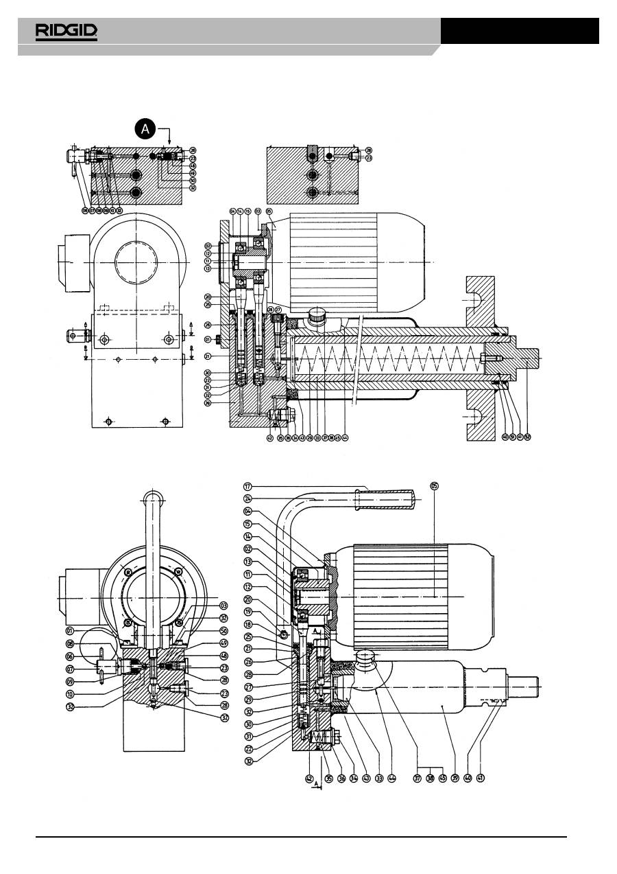
DETAIL OF MAXIMUM
PRESSURE VALVE
ELECTRO-HYDRAULIC PUMPS
MAXIMUM PRESSURE 420 ATO
Оглавление
- Operating Instructions
- Bedienungsanleitung
- Instructions d’utilisation
- Gebruiksaanwijzing
- Istruzioni operative
- Instrucciones de uso
- Instruções de Funcionamento
- Driftsinstruktioner
- Betjeningsvejledning
- Brukerveiledning
- Käyttöohjeet
- Upute za rukovanje
- Instrukcja obs ł ugi
- Instruc ţ iuni de exploatare
- Návod k obsluze
- Használati útmutató
- Οδηγίες λειτουργίας
- Инструкция по эксплуатации
