Ridgid K-1000: инструкция
Раздел: Электроинструменты
Тип:
Инструкция к Ridgid K-1000

K-1000 Rodder
K-1000 Rodder
WARNING!
Read this Operator’s Manual
carefully before using this
tool. Failure to understand
and follow the contents of
K-1000 Rodder
this manual may result in
Record Serial Number below and retain product serial number which is located on nameplate.
electrical shock, fire and/or
Serial
serious personal injury.
No.

K-1000 Rodder
Table of Contents
Recording Form For Machine Serial Number......................................................................................................................................................1
Safety Symbols......................................................................................................................................................................................................................3
General Safety Information ...........................................................................................................................................................................................3
Work Area Safety ...............................................................................................................................................................................................................3
Personal Safety ..................................................................................................................................................................................................................3
Tool Use and Care .............................................................................................................................................................................................................3
Service ...................................................................................................................................................................................................................................4
Specic Safety Information ...........................................................................................................................................................................................4
Machine Safety ..................................................................................................................................................................................................................4
Description, Specications and Standard Equipment .................................................................................................................................5
Description ..........................................................................................................................................................................................................................5
Specications .....................................................................................................................................................................................................................5
Standard Equipment.......................................................................................................................................................................................................5
Machine Assembly ..............................................................................................................................................................................................................6
Instructions for Installing Handle and Throttle Cable ......................................................................................................................................6
Instructions for Engine ...................................................................................................................................................................................................6
Instructions for Assembling Rods and Tools ........................................................................................................................................................6
Machine Inspection ............................................................................................................................................................................................................6
Machine and Work Area Set-Up ..................................................................................................................................................................................7
Operating Instructions .....................................................................................................................................................................................................7
Operating Rodder ............................................................................................................................................................................................................8
Accessories ..............................................................................................................................................................................................................................9
Maintenance Instructions...............................................................................................................................................................................................9
Torque Limiter ....................................................................................................................................................................................................................9
Torque Limiter Adjustment Using Torque Wrench ...........................................................................................................................................9
Torque Limiter Adjustment Using Spring Scale .............................................................................................................................................. 10
Engine ................................................................................................................................................................................................................................. 11
Transmission .................................................................................................................................................................................................................... 11
Centrifugal Clutch ......................................................................................................................................................................................................... 11
Wheel Assemblies ......................................................................................................................................................................................................... 11
Checking Engine Idle (RPM) Speed ....................................................................................................................................................................... 11
Throttle Adjustment ..................................................................................................................................................................................................... 11
“V” Belt Tension Adjustment ..................................................................................................................................................................................... 11
Main Bearings .................................................................................................................................................................................................................. 11
Storing of Rods ............................................................................................................................................................................................................... 11
Tool Storage ......................................................................................................................................................................................................................... 11
Service and Repair ........................................................................................................................................................................................................... 12
Lifetime Warranty ........................................................................................................................................................................................... Back Cover
* Original instructions - English
2

K-1000 Rodder
Safety Symbols
In this operator’s manual and on the product, safety symbols and signal words are used to communicate important
safety information. This section is provided to improve understanding of these signal words and symbols.
This is the safety alert symbol. It is used to alert you to potential personal injury hazards. Obey all safety messages that
follow this symbol to avoid hazardous possible injury or death.
DANGER
DANGER indicates a hazardous situation which, if not avoided, will result in death or serious injury.
WARNING
WARNING indicates a hazardous situation which, if not avoided, could result in death or serious injury.
CAUTION
CAUTION indicates a hazardous situation which, if not avoided, could result in minor or moderate injury.
NOTICE
NOTICE indicates information that relates to the protection of property.
Remove adjusting keys before turning the
General Safety Information
tool ON. A wrench or a key that is left attached to
a rotating part of the tool may result in personal
WARNING
injury.
Read and understand all instructions. Failure to fol-
low all instructions listed below may result in fire
Do not over-reach. Keep proper footing and
and/or serious personal injury.
balance at all times. Proper footing and balance
enables better control of the tool in unexpected
SAVE THESE INSTRUCTIONS!
situations.
Keep this manual with the equipment for use by the
Use safety equipment. Always wear eye pro-
operator.
tection. Dust mask, non-skid safety shoes, hard
hat, or hearing protection must be used for ap-
Work Area Safety
propriate conditions.
Keep your work area clean and well lit. Clut-
tered benches and dark areas invite accidents.
Tool Use and Care
Do not operate power tools in explosive atmo-
Do not force tool. Use the correct tool for your
spheres, such as in the presence of ammable
application. The correct tool will do the job bet-
liquids, gases, or dust. Tools create sparks which
ter and safer at the rate for which it is designed.
may ignite the dust or fumes.
Store idle tools out of the reach of children
Keep bystanders, children, and visitors away
and other untrained persons. Tools are danger-
while operating a tool. Distractions can cause
ous in the hands of untrained users.
you to lose control.
Maintain tools with care. Keep cutting tools
Keep the engine at least one meter (3 feet) away
sharp and clean. Properly maintained tools with
from buildings and other equipment during op-
sharp cutting edges are less likely to bind and are
eration. Do not place ammable objects close to
easier to control.
engine. Procedures should be followed to prevent
Check for misalignment or binding of moving
re hazards and to provide adequate ventilation.
parts, breakage of parts, and any other condition
that may aect the tools operation. If damaged,
Personal Safety
have the tool serviced before using. Many acci-
Stay alert, watch what you are doing and use
dents are caused by poorly maintained tools.
common sense when operating a power tool.
Use only accessories that are recommended
Do not use tool while tired or under the inu-
by the manufacturer for your tool. Accessories
ence of drugs, alcohol, or medications. A mo-
that may be suitable for one tool may become
ment of inattention while operating power tools
hazardous when used on another tool.
may result in serious personal injury.
Keep handles dry and clean; free from oil and
Dress properly. Do not wear loose clothing
grease. Allows for better control of the tool.
or jewelry. Contain long hair. Keep your hair,
clothing, and gloves away from moving parts.
Loose clothes, jewelry, or long hair can be caught
in moving parts.
3

K-1000 Rodder
Service
When striking an obstacle that causes the
tool to hang-up, do not attempt to force the
Tool service must be performed only by quali-
machine by manually pushing on the ex-
ed repair personnel. Service or maintenance
posed rods. Do not uncouple rods that are in
performed by unqualied repair personnel could
a stressed condition. This will cause kinking and
result in injury.
whipping of the rods which could cause serious
When servicing a tool, use only identical re-
injury.
placement parts. Follow instructions in the
Do not overstress rods. Do not use badly worn
Maintenance Section of this manual. Use of
or bent rods. Be sure torque limiter is adjust-
unauthorized parts or failure to follow mainte-
ed properly to 50 ft.-lbs. (68 Nm) maximum.
nance instructions may create a risk of injury.
Overstressing rods because of obstruction can
be dangerous to operators as rods may twist or
Specific Safety Information
kink.
Use caution when handling gasoline. Refuel
WARNING
in well-ventilated area. Do not overll fuel
Read this operator’s manual carefully before using
tank and do not spill fuel. Make sure tank cap
the RIDGID K-1000 Rodder. Failure to understand
is closed properly. Gasoline is extremely am-
and follow the contents of this manual may result
mable and is explosive under certain conditions.
in fire and/or serious personal injury.
Never run the engine in an enclosed or con-
Call the Ridge Tool Company, Technical Service Depart-
ned area. Exhaust contains poisonous carbon
ment at (800) 519-3456 if you have any questions.
monoxide gas; exposure may cause loss of con-
SAVE THESE INSTRUCTIONS!
sciousness and may lead to death. Exhaust also
contains chemicals that the State of California be-
Keep this manual with the K-1000 Rodder for use by the
lieves may cause cancer or reproductive harm.
operator.
Be careful not to touch the muer while it is
hot. To avoid severe burns or re hazards, let
Machine Safety
the engine cool before transporting or storing
Wear leather gloves provided with the ma-
it indoors. The muer becomes very hot during
chine. Never grasp a rotating rod with a rag or
operation and remains hot for a while after stop-
loose tting cloth glove. Could become wrapped
ping the engine.
around the rod and cause serious injury.
Only use the K-1000 to clean straight drain
Wear safety glasses and rubber soled, non-slip
lines 8” to 24” (200 mm - 600 mm) in diameter.
shoes. Use of this safety equipment may prevent
Follow instructions on the use of the machine.
serious injury.
Other uses or modifying the rodder for other ap-
Never operate machine with guards removed.
plications may increase the risk of injury.
Fingers can be caught between the chain sprocket.
Do not use tool if releasing the throttle does
Do not operate machine in (REV) reverse.
not stop the rod rotation. Any tool that cannot
Operating machine in reverse can result in rod
be controlled is dangerous and must be repaired.
damage and is used only to back tool out of an
obstruction.
The EC Declaration of conformity (890-011-320.10)
will accompany this manual as a separatebooklet
Shift lever must also be in NEUTRAL (straight up)
when required.
position when adding or removing tools and rod
If you have any question concerning thisRIDGID®
or any other time when machine is not in use. Pre-
product:
vents unexpected rotation of rods.
– Contact your local RIDGID distributor.
Disconnect spark plug when performing
– Visit www.RIDGID.com orwww.RIDGID.eu to nd
maintenance on Rodder or engine. This action
your localRIDGID contact point.
will prevent accidental starting and serious injury.
– Contact RIDGID Technical Services Departmentat
Operate rodder properly. Do not operate with
rtctechservices@emerson.com,or in the U.S. and
more than 20 feet (6 m) of rod between ma-
Canada call (800) 519-3456.
chine and manhole. The arcing of rod at man-
hole should not exceed 3 feet (90 cm). This will
minimize the possibility of kinking rods and seri-
ous injury.
4

K-1000 Rodder
Rods
Description, Specifications and
Standard Equipment
Catalog
Model
No.
No. Description
60355 A-2474 3' (0,9 m)Solid Sectional Rod, includes R-1 Male
Description
and R-2 Female Couplings
The RIDGID Model K-1000 Rodder is a gasoline, engine-
60360 A-2475 5' (1,5 m) Solid Sectional Rod, includes R-1
Male and R-2 Female Couplings
driven machine for cleaning straight line work in sewer
mains, drain tile, water mains and process piping. Will
60365 A-2475 10' (3,0 m) Solid Sectional Rod, includes R-1
Male and R-2 Female Couplings
clean drains 8” to 24” (200 mm - 600 mm) in diameter
and 500 feet (152 m) in length. The machine uses sec-
tional solid rods that have a quick coupler for connect-
ing or disconnecting tools and rods.
Tools and Replacement Blades
Catalog
Model
Specifications
No.
No. Description
62045 T-300 Spear Head
Line Capacity..................................... 8” – 24” (200 mm - 600 mm) dia.
1
Drain/Sewer Line
62050 T-301 Round Stock Corkscrew, 1
/
2
” (30 mm)
62055 T-302 Round Stock Corkscrew, 2” (50 mm)
Transmission (2 speed):
1
62060 T-303 Round Stock Corkscrew, 2
/
2
” (65 mm)
FWD Gear...................... 133 RPM
62065 T-304 Round Stock Corkscrew, 3” (75 mm)
REV Gear........................
133 RPM
1
62070 T-305 Round Stock Corkscrew, 3
/
2
” (90 mm)
Throttle................................................ Variable speed, returns
62075 T-306 Double Corkscrew, 3” (75 mm)
speed to idle when operator
releases grip
62080 T-307 Double Corkscrew, 4” (100 mm)
Engine.................................................. 4 cycle, gasoline, 6hp
62085 T-308 Double Corkscrew, 5” (125 mm)
Vertical shaft
62090 T-309 Square Stock Corkscrew, 3” (75 mm)
Clutch................................................... Centrifugal clutch open when
operator releases throttle
62095 T-310 Square Stock Corkscrew, 4” (100 mm)
62100 T-311 Square Stock Corkscrew, 5” (125 mm)
Length................................................. 32” (81 cm)
62105 T-312 Square Stock Corkscrew, 6” (150 mm)
Width.................................................... 26” (66 cm)
62370 T-313 Square Stock Corkscrew, 8” (200 mm)
Height (assembled
with handle........................................
40” (102 cm)
62375 T-314 Square Stock Corkscrew, 10” (250 mm)
Weight
62380 T-315 Square Stock Corkscrew, 12” (280 mm)
Machine only....................................
160 lbs. (73 kg)
62110 T-316 Auger, 3” (75 mm)
Standard Equipment
62115 T-317 Auger, 4” (100 mm)
62120 T-318 Auger, 5” (125 mm)
Catalog
Model
No.
No. Description
62125 T-319 Auger, 6” (150 mm)
59175 K-1000 Rodder Machine, includes:
62385 T-320 Auger, 8” (200 mm)
– B-3542 Rod Driver
62390 T-321 Auger, 10” (250 mm)
– A-2704 Tool Driver
62140 T-326 Pick-Up Tool
– A-3567 Drive Pin
– R-0 Rod Turner
– A-4558 Torque Adapter
– A-12 Coupling Pin Key
– A-1 Operator’s Mitt (LH)
– A-2 Operator’s Mitt (RH)
84295 K-1000 Rodder Machine, same as above, plus:
5
– 20 Sections of A-2475,
/
16
” (8 mm) Rod, Total
of 100 feet (30 m)
– T-300 Spear Head Cutter
– T-317 Auger
– T-326 Pick-Up Tool
5

K-1000 Rodder
The following Heavy-duty Cable Tools are also
Instructions for Engine
recommended for use with rod.
1. Engine is shipped without oil. Fill with oil prior to
starting engine (See enclosed Engine Owner’s Man-
Catalog
Model
Replacement
No.
No. Description
Blade(s)
ual for details).
61800 T-2 Heavy-Duty Straight Auger —
61790 T-4 Heavy-Duty Funnel Auger —
CAUTION
Failure to ll engine with oil will result in
63200 T-7 Hook Auger —
61960 T-16 Spiral Bar Cutter, 4” (100 mm) 97855
engine failure.
61850 T-17 Spiral Bar Cutter, 6” (150 mm) 97955
Instructions for Assembling Rods and Tools
61855 T-18 Spiral Bar Cutter, 8” (200 mm) 97960
1. To connect rods, align and snap the couplings to-
63085 T-23 Spiral Sawtooth Cutter,
97850
4” (100 mm)
gether for a solid connection (Figure 2).
1
59765 T-24 4-Blade Cutter, 2
/
2
” (65 mm) 97940
1
59770 T-25 4-Blade Cutter, 3
/
2
” (90 mm) 97975
1
59775 T-26 4-Blade Cutter, 4
/
2
” (115 mm) 97805
1
59780 T-26A 4-Blade Cutter, 5
/
2
” (140 mm) 97980
Figure 2 – Connecting/Disconnecting Rods
Machine Assembly
2. To disconnect, insert pin key and slide couplings
WARNING
apart.
To prevent serious injury, proper assembly of the
K-1000 Rodder is required. The following proce-
Machine Inspection
dures should be followed:
WARNING
Instructions for Installing Handle and
Throttle Cable
1. Insert handle assembly into handle openings in
3
base and attach by means of four
/
8
” bolts provid-
ed (Figure 1).
2. Attach free end of throttle cable to throttle handle
and secure cable to left side of handle with two
cable clamps provided.
To prevent serious injury, inspect your Rodder. The
following inspection procedures should be per-
formed on a daily basis:
Throttle Cable Handle
and Stop Nut
1. Check engine crankcase oil level. If low, add oil (see
enclosed Engine Owner’s Manual for details).
Throttle Cable
2. Check engine fuel level. If low, add unleaded gaso-
line with a pump octane rating of 86 or higher. (See
Shift Lever
enclosed Engine Owner’s Manual for details).
WARNING
Use caution when handling gasoline. Re-
fuel in well-ventilated area. Do not over ll fuel tank and
Handle
Assembly
do not spill fuel. Make sure tank cap is closed properly.
3. Inspect the rodder for any broken, missing, mis-
aligned or binding parts as well as any other con di-
tions which may aect the safe and normal opera-
tion of the machine. If any of these conditions are
Rod Holder
present, do not use the Rodder until any problem
has been repaired.
Figure 1
6

K-1000 Rodder
4. Lubricate the Rodder, if necessary, according to the
2. Place machine 20 feet (6 m) from manhole. Greater
Maintenance Instructions.
distance can result in kinking and whipping of rods.
5. Use tools and accessories that are designed for
3. Transmission shift lever should be in NEUTRAL
your rodder and meet the needs of your applica-
(straight up) position.
tion. The correct tools and accessories will allow
4. Select and install proper tool/cutter to end of rod.
you to do the job successfully and safely. Accesso-
To connect, snap the male and female couplings
ries suitable for use with other equipment may be
together. To disconnect, insert pin key and slip
hazardous when used with this rodder.
apart (Figure 2).
6. Clean any oil, grease or dirt from all equipment
5. Couple enough rod together to reach down into
handles and controls. This reduces the risk of injury
main and extend out no more than 20 feet (6 m).
due to a tool or control slipping from your grip.
7. Inspect the cutting edges of your tools. If neces-
Operating Instructions
sary, have them sharpened or replaced prior to us-
ing the Rodder. Dull or damaged cutting tools can
WARNING
lead to binding and rod kinking.
8. Inspect rod and couplings for wear and damage.
Rods should be replaced when they become se-
verely worn, corroded or bent.
WARNING
Worn or damaged rods can break causing
serious injury.
9. Depending on use, torque limiter should be
Rods may whip or kink. Fingers, hands or other
checked every month. The purpose of the torque
body parts can be crushed or broken. Carbon mon-
limiter is to minimize kinking of the rods because
oxide poisoning can occur if operated in a confined
of excessive torque caused by heavy blockage
area.
within pipe. Torque limiter must be adjusted to a
Wear gloves provided with machine. Never grasp a
maximum of 50 ft.-lbs. (600 in.-lbs.) (68 Nm). Refer
rotating rod with a rag or loose fitting cloth glove
to Adjustment Procedure in Main tenance Section.
that may become wrapped around the rod causing
WARNING
Improperly adjusted torque limiter can
serious injury.
result in kinking of the rods and serious injury.
Always wear eye protection to protect your eyes
against dirt and other foreign objects. Wear rubber
Machine and Work Area Set-Up
soled, non-slip shoes.
WARNING
WARNING
Always follow the correct operating pro-
cedure in order to maintain proper control of the ma-
chine and rods and prevent serious injury (Figure 3).
required. Machine operator and rod handler at
manhole.
To prevent serious injury, proper set-up of the ma-
rod between machine and manhole.
chine and work area is required. The following pro-
cedures should be following to set-up the machine.
feet (90 cm).
1. Check work area for:
-
chine before shifting transmission. Violent whip-
ping action of rods could cause serious injury.
-
chine by manually pushing in the exposed rods.
WARNING
Exhaust contains poisonous carbon
mon oxide gas. Exposure may cause loss of conscious-
ness and may lead to death.
7

K-1000 Rodder
Operating Rodder
WARNING
When striking an obstacle that causes
1. Transmission shift lever should be in NEUTRAL
tool to hang-up, do not attempt to force the machine by
(straight up) position.
manually pushing on the exposed rods. This will cause
2. Set choke control handle to CHOKE and turn en-
kinking and whipping of the rods.
gine over a few times with pull starter.
3. When engine catches, set at RUN and pull throttle
Leather Mittens
(Standard Equipment)
control to desired speed.
NOTICE
Squeeze throttle handle to REV engine at high
speed and immediately release so that engine returns to
idle.
WARNING
At idle speed, the drive shaft should not
be turning. If drive shaft does turn, make sure that throt-
3’ (90 cm)
tle control spring is connected or adjust idle speed at the
(Max.)
throttle cable handle by loosening stop nut and adjust-
20’ (6 m)
ing cable length (Figure 1).
(Max.)
4. Position rod assembly at manhole.
Warning:
5. Holding onto both ends of a piece of rope, lower
Do not ever shift transmission.
auger or probing tool into manhole, guiding tool
To release a kink in Rod, untill
towards lateral opening.
man at manhole is behind
machine. Violent whipping
6. Use a hand-operated rod turner and feed rod a
action of Rod could cause
serious injury.
short distance into lateral opening.
7. Release one end of rope and remove from manhole.
8. Couple rod to machine to rod holder (Figure 1).
Lateral Opening
Figure 3 – Operating Rodder
WARNING
Make certain that rod handler is wearing
standard equipment leather mittens with riveted palms.
4. If tool gets hung up in obstruction, release throttle
Use no substitute.
handle. Put machine in reverse gear, squeeze throt-
tle control and pull machine back to release tool.
9. Place transmission shift lever in FWD gear.
10. Squeeze throttle handle for desired rod (RPM) rota-
tion and push machine forward.
WARNING
Only operate machine in reverse to back
11. As machine is pushed forward, the rod handler
tool out of obstruction.
should push downward on rod with rod guided
between thumbs and palms of hands with ngers
WARNING
extended (Figure 3).
If kinking of rod occurs, move all people to rear
of machine before shifting transmission. Violent
WARNING
whipping action of rod could cause serious injury.
The arcing of rod at manhole should not exceed
3 feet (1 m).
1. If rod kinking occurs, release throttle to return en-
1. When machine is approximately 8 feet (2,5 m) from
gine to idle speed. Be sure all personnel are to the
manhole, release throttle handle and place transmis-
rear of the machine. Back the machine to remove
sion shift lever in NEUTRAL (straight up) position.
all slack from the rods. Shift transmission to neutral
2. Uncouple rod from rod holder, move machine back
to insure all torque is released.
approximately 10 feet (3 m) and connect additional
2. Proceed through obstruction with transmission
rods.
shift lever in FWD gear.
3. After clearing obstruction continue through line to
WARNING
Do not uncouple rod in stressed condi-
make sure that it is clear.
tions.
4. When completed, leave transmission shift lever
3. Continue feeding rod by following steps 9 through
in FWD gear and back machine away from sewer
13 until through an obstruction.
opening.
8

K-1000 Rodder
5. With approximately 20 feet (6 m) of rods are re-
Maintenance Instructions
moved from the manhole, place transmission shift
lever in neutral (straight up) position.
WARNING
6. Uncouple rod from rod holder and disconnect rods
Disconnect spark plug when performing mainte-
by inserting pin key and sliding coupling apart
nance on rodder or engine.
(Figure 2).
Torque Limiter
(Figures 4 & 5)
WARNING
Do not uncouple rod in stressed condi-
tion.
The purpose of the torque limiter is to minimize kink-
7. Move machine to manhole and connect rod to rod
ing of rods and excessive torque through the transmis-
holder. Place machine in FWD gear and follow steps
sion system. Kinking is caused by heavy blockage within
19 through 21 until all the rods have been removed
pipe and must be adjusted to no more than 50 ft.-lbs.
from the main.
(600 inch-lbs.) (68 Nm).
8. Move choke control handle to STOP position to
The torque limiter consists of two ber discs with one
shift o engine.
assembled on either side of the drive sprocket A-3569.
When clamped against sprocket, the torque limiter pro-
Accessories
duces the only connection between drive shaft B-3548
and drive sprocket A-3569.
WARNING
Only the following RIDGID products
have been designed to function with the K-1000 Rod-
Torque Limiter Adjustment Using Torque
der. Other accessories suitable for use with other tools
Wrench
may become hazardous when used on the K-1000. To
prevent serious injury, use only the accessories listed
(Figures 4 & 5)
below.
1. Disconnect spark plug wire.
2. Remove 3 screws and guard to expose torque limiter.
Catalog
Model
No.
No. Description
3. Back o three cap screws so they do not contact
59835 K-10 Complete Set of Quick-Connect Rod
backup plate. They are now free to be turned by
Couplings:
One Each R-1 and R-2
hand.
59560 R-1 Male Rod Coupling
4. Back o torque limiter threaded ring until it turns
59555 R-2 Female Rod Coupling
freely. Hand-tighten torque limiter threaded ring
61875 R-7 Male Tool Coupling, connects
against backup plate.
Tool Adapter to Rodding Tool
61885 R-8 Female Tool Coupling, connects
5. Hand-tighten three cap screws to make contact
Tool to Tool Adapter
with backup plate.
60700 A-2704 Tool Adapter, includes R-2 and R-7 Couplings
NOTICE
This insures that all three screws provide
62170 B-3542 Rod Holder For K-1000
even pressure against backup late at beginning of
61895 — Rod Driver for K-2000
torque adjustment.
62815 R-O Rod Turner, used to manually turn Rods in
3
6. Insert a
/
short runs
16
” hex key or pin through both sides of
chain near drive sprocket to lock chain.
59205 A-1 Left-Hand Mitt
59295 A-2 Right-Hand Mitt
7. Insert torque testing tool into shaft B-3548 and
lock in place with drive pin.
59360 A-3 Tool Box
8. Install a 1 inch socket on torque wrench and apply
59225 A-12 Coupling Pin Key
torque to torque testing tool. Record torque read-
ing at which torque limiter slips.
9. If torque reading is less than 50 ft.-lbs. (68 Nm)
tighten the 3 cap screws uniformly and recheck
torque reading. If torque reading is greater than
50 ft.-lbs. (68 Nm) loosen the 3 cap screws uniform-
ly and recheck torque reading.
1
NOTICE
Turn cap screws
/
4
turn for initial adjustment.
1
Reduce to
/
8
turn or less for nal adjustment to ob-
tain 50 ft.-lbs. (68 Nm) reading.
9
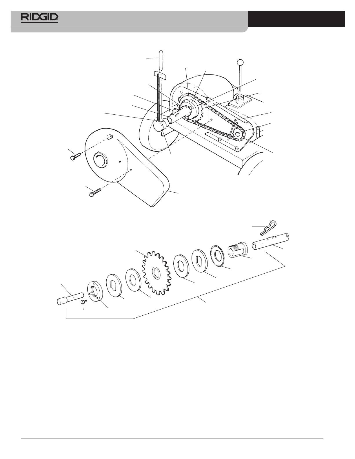
K-1000 Rodder
Torque Wrench
(50 Ft. Lb. (68 Nm)
Reading Required)
Threaded Ring
Backup Plate
Fiber Disc
Cap Screw (3)
Drive Sprocket A-3569
Drive Pin
Drive Shaft A-3548
1” Socket
Hex Key or Pin
Drive Sprocket
Screw (2)
Chain A-3568
Torque Testing Tool
Screw (Long)
Guard
Figure 4 – Adjusting Torque Limiter
Drive Pin
Drive Sprocket
Drive Shaft
Threaded Ring
Retainer
Pressure Plate
Torque Testing
Tool
Backup Plate
Fiber Disc
Fiber Disc
Backup Plate
Torque Limiter
Threaded Ring
Cap Screw (3)
Figure 5 – Torque Limiter, Torque Testing Tool, Drive Sprocket and Drive Shaft
10. Remove hex key or pin that was installed to secure
Torque Limiter Adjustment Using Spring
chain.
Scale
11. Remove torque wrench, drive pin and torque test-
1. Follow steps 1 through 7 of Torque Limiter Adjust-
ing tool.
ment using Torque Wrench.
12. Install guard and secure with 3 screws. One screw is
2. Snap socket drive handle into a 1 inch socket and
longer than others and is used in lower right hand
install on torque testing tool.
side.
3. Measure 12 inches (30 cm) from center of socket
13. Connect spark plug.
along socket drive handle and attach spring scale.
4. Pull on spring scale until torque limiter slips. Scale
should read 50 lbs (22 kg).
10

K-1000 Rodder
5. Repeat step 9 above until 50 lbs. (22 kg) reading is
“V” Belt Tension Adjustment
obtained.
“V” Belt should be checked at least once a month. Belt
tension should be just enough to drive maximum load
at high speed with throttle open. Excess belt tension will
Engine
cause the centrifugal clutch to creep at idle speed. “V”
Always check engine oil level. For complete directions
Belt is tightened by loosening engine mounting bolts
on engine maintenance, consult the Engine manual en-
and sliding engine to rear.
closed.
Main Bearings
Transmission
The Main Bearings should be greased after using ma-
The transmission needs no relubrication, however, a leak
chine on 12 jobs or once every three months, whichever
in a seal could allow grease to be depleted after several
comes rst. Guard must be removed to grease front
hours. Such a leak will be obvious and should be cor-
main bearing. Chain should be checked and greased
rected.
while guard is removed.
Centrifugal Clutch
WARNING
Do not use machine with guard re-
Centrifugal clutch will automatically engage when the
moved.
throttle is opened. No maintenance should be necessary.
However, if slippage should occur from dirt or grease en-
Storing of Rods
tering clutch, the foreign material should be removed.
Rods should be thoroughly ushed with water to pre-
vent damaging eect of some drain cleaning com-
Wheel Assemblies
pounds. Periodically, lubricate rods and couplings with
All four wheel assemblies should be greased once a year.
oil. When storing, uncouple rods. Do not store in a coil
The grease tting is located on the inside face of the
since this could cause bending and damage.
hub.
Checking Engine Idle (RPM) Speed
Tool Storage
After engine has started, squeeze throttle handle to rev
WARNING
Motor-driven equipment must be in-
engine at high speed and immediately release so that
doors or well covered in rainy weather. Store the ma-
engine returns to idle.
chine in a locked area that is out of reach of children and
people unfamiliar with machine. This machine can cause
serious injury in the hands of untrained users.
WARNING
At idle speed the drive shaft should not
be turning. If drive shaft does turn, make sure that Throt-
tle Control Spring is connected or adjust idle speed at
the throttle cable handle by loosening stop nut and ad-
justing cable length (Figure 1).
Throttle Adjustment
Throttle control is factory set and should not require ad-
justment. If idle speed seems too high or engine does
not speed up when throttle is pulled check throttle link-
age.
1. Check speed adjustment by adjusting cable posi-
tion; loosen clamp at bracket and move slightly.
2. For idle adjustment and mixture control, refer to
engine manual enclosed.
11

K-1000 Rodder
Service and Repair
WARNING
The “Maintenance Instructions” will take care of most
of the service needs of this machine. Any problems not
addressed by this section should only be handled by an
authorized RIDGID service technician.
Machine should be taken to a RIDGID Independent Au-
thorized Service Center or returned to the factory. All
repairs made by Ridge service facilities are warranted
against defects in material and workmanship.
WARNING
When servicing this machine, only iden-
tical replacement parts should be used. Failure to follow
these instructions may create a risk of serious injury.
For information on your nearest RIDGID Independent
Service Center or any service or repair questions:
- Contact your local RIDGID distributor.
- Visit www.RIDGID.com or www.ridgid.eu to nd
your local RIDGID contact point.
- Contact RIDGID Technical Services Department
at rtctechservices@emerson.com, or in the U.S.
and Canada call (800) 519-3456
12
