Ridgid SeekTech ST-305: инструкция
Раздел: Инструмент, электроинструмент, силовая техника
Тип: Линейный Передатчик
Инструкция к Линейному Передатчику Ridgid SeekTech ST-305
SeekTech
ST-305
GB p. 1
DE p. 13
FR p. 25
NL p. 39
IT p. 51
ES p. 63
PT p. 75
DA p. 87
NO p. 99
PL p. 111
RU p. 126
RIDGE TOOL COMPANY
Ridge Tool Company
1
Tools For The Professional
TM
®
SeekTech
ST-305
• Exposing the utility is the only way to verify its
existence, location, and depth.
GB
• Ridge Tool Co., its aliates and suppliers, will not be
liable for any injury or any direct, indirect, incidental
SeekTech ST-305
or consequential damages sustained or incurred by
reason of the use of the SeekTech ST-305.
Operating Instructions
DANGER
General Safety Information
• ALWAYS HOOK UP LEADS FIRST BEFORE POWERING THE
WARNING! Read these instructions
UNIT ON TO AVOID SHOCK.
and the accompanying safety booklet
• ALWAYS TURN UNIT OFF BEFORE DISCONNECTING
carefully before using this equipment.
LEADS.
If you are uncertain about any aspect of using
this tool, contact your RIDGID distributor for
• ELECTRIC SHOCK MAY RESULT FROM FAILURE TO
more information.
CONNECT LEADS BEFORE POWERING THE UNIT ON.
Failure to understand and follow all
• Do not handle the transmitter while you are connected
directly to ground yourself.
instructions may result in electric shock,
re, and/or serious personal injury.
• Wear appropriate heavy soled footwear as you would
when working with any high-voltage equipment.
SAVE THESE INSTRUCTIONS!
NOTE: The line transmitter is normally powered by internal
batteries, and is designed to protect the user from voltages
up to 250 VAC that may be accidentally encountered. Battery
CAUTION: Remove batteries entirely before shipping.
power is the sole power option available on the ST-305. The
High Voltage LED will light if the unit encounters more than
If you have any questions regarding the service or
approximately 62 VAC (RMS).
repair of this machine, contact your Ridgid distributor,
your local Ridgid oce or Ridge Tool Europe at
info.europe@ridgid.com.
WARNING: In compliance with Federal Standard
EN-50249, the ST-305 line transmitter is designed to
In any correspondence, please give all the information shown
withstand up to 250 VAC 50/60 Hz excitation between
on the nameplate of your tool including model number and
the two leads.
serial number.
The user is cautioned not to deliberately connect to live
power lines. If the transmitter indicates the presence of
DANGER
high voltage, use high voltage precautions to carefully
disconnect the line transmitter from the high voltage
• The SeekTech ST-305 is intended for use with a SeekTech
source.
locator/reciever. The locator is a diagnostic tool that senses
electromagnetic elds emitted by objects underground.
It is meant to aide the user in locating these objects by
NOTE: The unit must be disconnected from any external
recognizing characteristics of the eld lines and displaying
conductors before attempting to access the battery case or
them on the screen. As electromagnetic eld lines can be
change the batteries. The ST-305 is protected by an interlock
distorted and interfered with it is important to verify the
which isolates the unit when the battery case is opened, but
location of underground objects before digging.
standard safety awareness dictates disconnecting the leads
rather than relying solely on this feature.
• Several utilities may be underground in the same
area. Be sure to follow local guidelines and one-call
service procedures.
2
Ridge Tool Company
Tools For The Professional
TM
®
SeekTech
ST-305
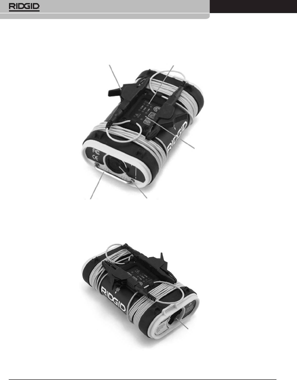
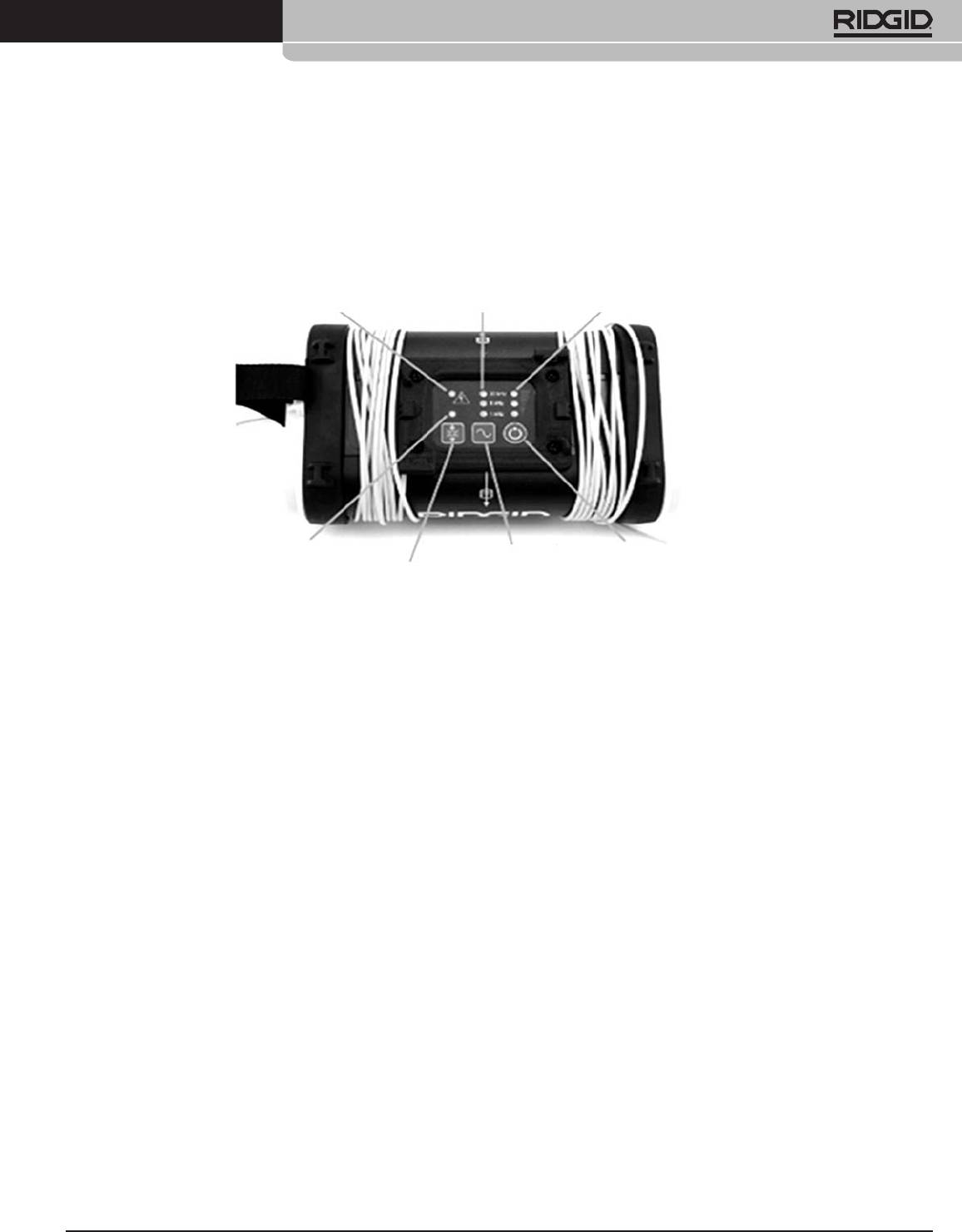
Transmitter Components
Frequency, Mode and Power LEDsConnection Leads and Clips
Keypad
Inductive Clamp Jack
Ground Stake Storage
Battery Case
Figure 1: ST-305 Components
Ridge Tool Company
3
Tools For The Professional
TM
®
SeekTech
ST-305
Keypad
High Voltage Warning Frequency Indicator
Power Indicator
Induction Mode Indicator
Frequency and
Power On/O/Select
Induction Mode Toggle
Mode Selection
Figure 2: Keypad and Display
• Frequency Indicator: Indicates frequency in use; indicates when dual-frequency mode is activated.
• Power Indicator: Indicates the relative level of output power; displays estimated battery power level on start-up.
• Frequency/Mode Selection: Selects desired frequency; used to initiate dual-frequency mode.
• Power On/O: Used to power the ST-305 on and o and to set current level.
• Induction Mode Toggle: Used to switch the ST-305 into Inductive Mode.
• Induction Mode Indicator: Flashes when unit is connected to an Inductive Clamp. Illuminated in Inductive Mode.
• High Voltage Warning: Warning light when high voltage is encountered (> ~62V AC RMS).

4
Ridge Tool Company
Tools For The Professional
TM
®
SeekTech
ST-305
Automatic Shut Down
Getting Started
To save energy, the ST-305 will automatically shutdown after
Installing/Changing Batteries
an interval which varies with the power setting:
Low Power 4 hours
Medium Power 2 hours
High Power 1 hour
Battery Check
At start-up, the ST-305 will check available power and will
indicate estimated battery levels by lighting one, two, or
three LEDs in the right hand column (power level) on the
control panel. These levels are only estimates based on a
rapid internal check. A rapid series of beeps will sound if the
battery levels run low in operation.
Figure 3: Removing the Battery Cover
Sounds of the ST-305 Transmitter
NOTE: When replacing batteries, use 6 C cells that are the
same type. Do not mix half used alkalines with brand new
Sounds are associated with specic events or states.
ones.
They include:
• Beeps – Beeps when current is owing; rate increases
CAUTION: Remove batteries entirely before shipping.
with current increase.
• Beeps – Turn ON (4 beeps)/OFF (3 beeps).
• Short Double Tone – Inductive Clamp connected.
Operation Time
• Long-Short-Short Tone – Inductive Mode.
Typical operation time varies for the ST-305, depending on
factors such as load, environment, and current transmitted.
• Rapid series of beeps – Low Battery Warning.
Other factors that aect the operation time will include
The sound may be toggled on or o by pressing the Frequency
chemistry of the battery (many of the new high performance
and Power buttons simultaneously.
batteries, such as the “Duracell ® ULTRA” last 10%-20%
longer than conventional alkaline cells under high demand
applications). Operation at low temperatures will also reduce
battery life.
Batteries often recover after being subjected to high loads.
If time is allowed, batteries may recover enough to oer
additional hours of operation.
Powering Up / Down
Turn the power ON by depressing the Power Key on the
keypad. The current frequency and power level LEDs will
light up. A beep will sound.
Turn the unit OFF by depressing the Power
Key on the
keypad for 2 seconds. Three tones will sound.

Ridge Tool Company
5
Tools For The Professional
TM
®
SeekTech
ST-305
Direct Connect – The transmitter’s leads are connected
Using the ST-305 Line Transmitter
directly to the target conductor and a suitable ground.
The ST-305 line transmitter can apply an active tracing signal
The ST-305 is capable of dual-frequency transmission
to a target conductor in three ways:
(sending two frequencies onto a line simultaneously) in
direct-connect mode. See page 7.
Inductive Clamp – The jaws of the inductive clamp encircle
the target conductor; there is no metal-to-metal contact.
(The inductive clamp is an optional accessory). See page 7.
Inductive Mode (internal coils) – The transmitter is placed
over, and in-line with, a conductor. Its internal antenna
generates a dipole eld which energizes the target conductor
below ground, inducing a current into the target conductor.
See page 8.
DANGER! Always connect leads before turning the
Figure 4
transmitter on to avoid electrical shock. Ensure transmitter
is well grounded.
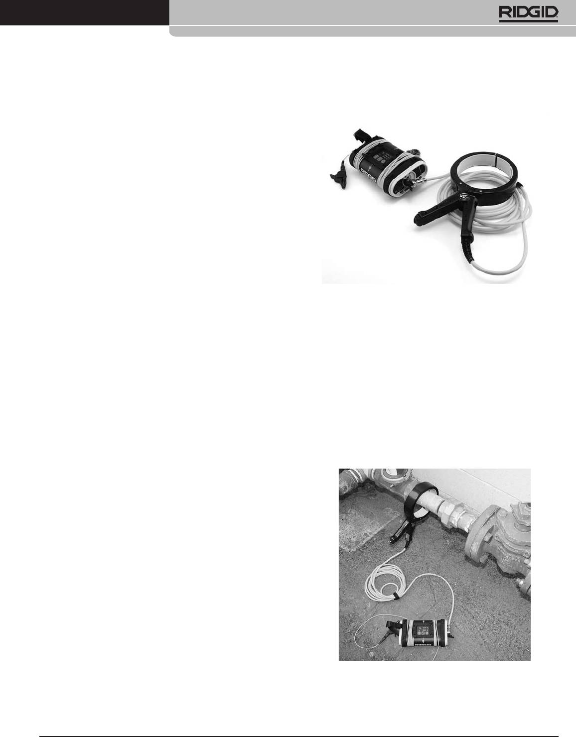
Direct-Connect Method
1. Attach the ST-305 line transmitter to
ground and to the target line
Insert the ground stake into the ground. Connect one of the
cable leads.
Connect the other lead to the target conductor.
Figure 5
Figure 7: Connecting the ST-305 to a Line
Figure 6
6
Ridge Tool Company
Tools For The Professional
TM
®
SeekTech
ST-305
Power Settings
WARNING! NEVER CONNECT TO LINES KNOWN TO BE
There are 3 power settings available:
ENERGIZED WITH A POTENTIALLY DANGEROUS ELECTRICAL
CURRENT. To increase safety, the ground lead should be
• Low power (approximately .5 watt)
attached rst. If there were an unknown high voltage
• Medium power (approximately 2.0 watts)
running through the target line, this would allow a means
of redirecting the current away from the transmitter and
• High power (approximately 5 watts)
operator.
Low power will provide the least current with the longest
battery life. Actual power output will vary with circuit
Power the ST-305 up.
resistance and frequency used. These values assume a
nominal 320-ohm load.
Select a Frequency on the Transmitter.
The transmitter’s maximum current output depends on the
Available frequencies are:
amount of resistance in the circuit.
1 kHz
CAUTION: If the transmitter is showing low or no current
8 kHz
(low or no beep rate), the signal may be too low to be detected
33 kHz
by the receiver locator and inadequate for tracing.
93 kHz
The selected frequency is shown by a lit LED. The 93 kHz
is shown by a rapid ashing of the 33 kHz LED. To set the
3. Check the Receiver
unit on 93 kHz, press the Frequency Key for more than one
second (long press). The 33 kHz LED will start ashing rapidly,
Conrm that the transmitter and receiver are set to the same
indicating a 93 kHz frequency.
frequency. Hold the receiver near the transmitter cables and
conrm a signal is being received.
2. Check the Circuit and Adjust Power
FCC Limits
Level
47 CFR 15.213 requires that from 9 kHz up to (but not
Conrm the circuit is grounded by checking the connection to
including) 45 kHz, peak output power shall not exceed 10 W.
the ground stake is secure and the stake is rmly embedded
From 45 kHz to 490 kHz, it must not exceed 1 W. When the
in the ground. To adjust the power level, press the power
ST-305 is set to 262 kHz (European version: 93 khz), the power
button briey. The ST-305 will cycle through the low, medium
output levels are limited:
and high power levels.
Low: 0.3 watt
NOTE: Higher power settings produce more current, which
Medium: 0.6 watt
gives a stronger signal. Less current prolongs battery life. Signal
High: 1 watt
strength measured by the receiver is directly proportional to
the amount of current on the line. More current will produce
These values assume a nominal load of 320 ohms.
a stronger signal received by the receiver.
Use only as much current as is needed to get a strong reading
on the receiver.
Generally the lower the resistance the more eciently current
can be added. A lower resistance indicates an ecient circuit
and requires less voltage to charge the line. Things that
increase resistance include paint or dirt on the connection
points, very dry soil, poor ground connection, poor insulation
on a wire, or breaks in the conductor.
Ridge Tool Company
7
Tools For The Professional
TM
®
SeekTech
ST-305
Useful Operating Tips
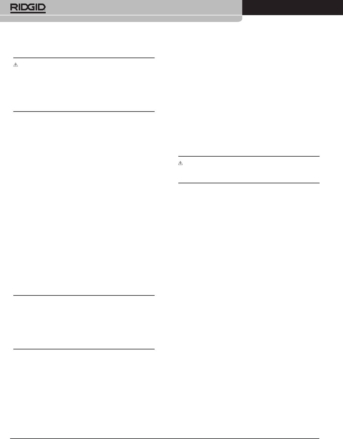
Inductive Clamp Method
• The lower the resistance, the more current will be put on
the line.
• Scrape away dirt, paint, and corrosion before connecting
to the target conductor or to the grounding spike.
• Insert the grounding spike as far as possible. Eventually
try wetting the area if necessary.
• Keep the transmitter leads short by stowing the excess
length on the transmitter’s body. This will reduce the
amount of interfering signals from the leads. Where
possible, place the transmitter away from the area of the
intended locate. This is especially true in Inductive Mode,
to avoid coupling through the air with the receiver.
• Start by using the lowest frequency and the least amount
of current needed to eectively illuminate the line. Lower
frequencies travel farther because they do not dissipate
Figure 8: ST-305 with Inductive Clamp
as quickly. Higher frequencies generally make it easier to
When using an inductive clamp, plug the inductive clamp
illuminate a line, but they don’t travel as far and are much
jack into the receptacle provided at the end of the transmitter.
more likely to couple onto other utility lines, distorting
The Inductive Mode LED will ash rapidly when a clamp
the signal and reducing the accuracy.
is connected. Clips and leads are not used. Note that for a
clear signal using an inductive clamp, both ends of the utility
Dual-Frequency Transmission
should be grounded.
The ST-305 can be placed in Dual-Frequency mode by
Clamp the inductive clamp around an accessible portion of
pressing the Frequency Key for over 1 second (long press). To
the line chosen to trace. The clamp will induce a signal into
exit Dual-Frequency mode, simply repeat the long press on
the conductor when the transmitter is powered on.
the Frequency Key. See Figure 2.
Select frequency and power as with the Direct Connect
When in Dual Frequency mode the Frequency Key will cycle
Method. Operational frequency choices for use with an
with
short presses through the following frequency settings:
Inductive Clamp are 1 kHz, 8 kHz, and 33 kHz.
1. 93 kHz only (rapid ashing 33kHz LED).
2. 33 kHz and 1 kHz dual-frequency transmission
(LEDs for 33 kHz and 1 kHz both lit).
3. 33 kHz and 8 kHz dual-frequency transmission
(LEDs for 33 kHz and 8 kHz both lit).
Dual-Frequency transmission is available only in direct
connect mode.
The advantage of dual frequency is that you combine the
advantage of a lower frequency (less risk to bleed over,
longer distance) with the advantage of the higher frequency
(a higher frequency can “jump” over small hurdles allowing
to continu the trace). Thus you start locating at a lower
frequency and when the signal stops due to eg a rusted valve,
you can switch to a higher frequency without the need to go
back to your transmitter and set the frequency at a higher
frequency.
Figure 9: Inductive Clamp Attached to a Conductor
8
Ridge Tool Company
Tools For The Professional
TM
®
SeekTech
ST-305
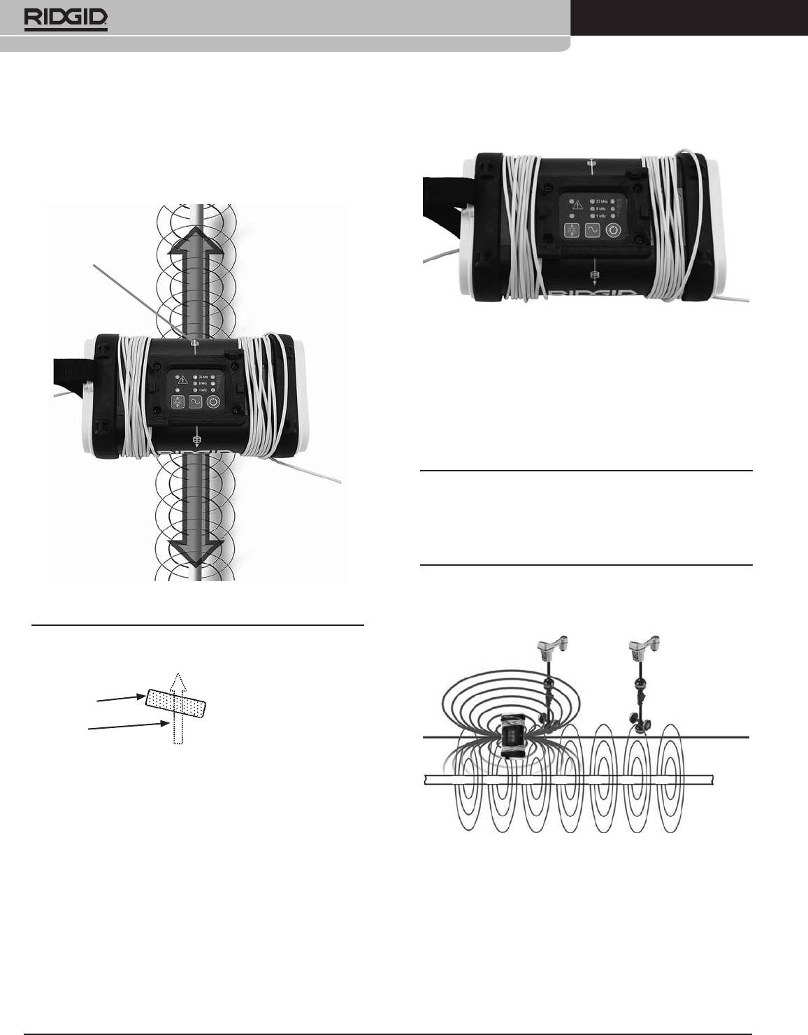
Inductive Mode
1. Be sure that the transmitter is positioned correctly
over the line.
Orientation
Guide
Figure 11: ST-305 in Inductive Mode at 33 kHz
4. Lower frequencies couple poorly. Therefore, the
ST-305 transmitter in Inductive Mode defaults to
33 kHz. Higher power is usually required for a clear
signal in Inductive Mode. Pressing the power key will
cycle through the three available power levels: 1 kHz,
8 kHz, and 33 kHz.
NOTE: If using the ST-305 in Inductive Mode, be certain to
switch Inductive Mode o if you are going to use the unit in
direct connect mode. Air coupling can create very confusing
signals if you inadvertently have the unit set to Inductive
Mode and are trying to use it in direct connect mode.
Figure 10: Orientation to the Line – Inductive Mode
Coupling through Air
NOTE: A slight tilt to the axis of the conductor can help
reduce the probability of air-coupling:
Transmitter
Conductor
2. Power the transmitter on. Push the Inductive Mode
switch to induce a signal onto the line without a direct
connection. (A long beep will sound when entering
Inductive Mode.) The Inductive Mode LED will light.
3. The transmitter will emit a series of regular beeps as
Figure 12: Near the transmitter, the receiver reads on the
long as it is in Inductive Mode.
local dipole eld around the transmitter.
It is important to set up the transmitter, when using the
Inductive Mode, a good 20 or 30 feet away from the region
where tracing occurs.

Ridge Tool Company
9
Tools For The Professional
TM
®
SeekTech
ST-305
High Voltage Indicator
Using High and Low Frequencies
Whenever the line transmitter encounters a live voltage on
High Frequencies:
the line higher than 62 VAC, it will ash a red LED at the top
• Don’t travel as far
of the keypad. Should this occur, carefully disconnect the
• Overcome some barriers
transmitter using high-voltage precautions.
• Bleed-over more
Useful Information
Low Frequencies:
• Travel further
Resistance and Impedance
• Lose signal when hitting barriers, gaskets, poor
insulation
Higher resistance reduces the amount of current that can
travel along an underground line. Factors that aect resistance
Do not bleed-over as much.
in the transmitter circuit are conductivity of the line itself,
As a general rule, detecting with lower frequencies is more
breaks or faults in the line, insulation problems with the line,
reliable for the reasons given above, IF you can get a good
and how well the transmitter is grounded. (Poor grounding
signal.
makes the return path of the circuit more resistive).
Grounding can be aected by soil conditions, length of
grounding rod, or how the line transmitter is connected to
Transportation and Storage
the grounding rod. Good grounding improves the signal
Before transporting make sure that the unit is powered OFF
by reducing the total resistance the transmitted current
to preserve battery power.
encounters.
Also make sure that the ST-305 line transmitter is secure
Impedance is a form of resistance which is caused by a back-
and does not bounce around or get bumped by loose
force in the electrical eld caused by alternating current (AC).
equipment.
Impedance can be thought of as “AC resistance” and adds to
the resistance in the circuit in proportion to the frequency
being used (i.e., higher AC frequencies add more impedance
CAUTION: Remove batteries entirely before shipping.
than lower ones).
The ST-305 line transmitter should be stored in a cool dry
place.
NOTE: If storing the ST-305 for an extended period of time,
the batteries should be removed.

10
Ridge Tool Company
Tools For The Professional
TM
®
SeekTech
ST-305
Maintenance and Cleaning
1. Keep the ST-305 line transmitter clean with a damp
cloth and some mild detergent. Do not immerse in
water.
2. When cleaning, do not use scraping tools or abrasives
as they may permanently scratch the display. NEVER
USE SOLVENTS to clean any part of the system.
Substances like acetone and other harsh chemicals
can cause cracking of the case.
Locating Faulty Components
For troubleshooting suggestions, please refer to the trouble
shooting guide at the end of the manual.
Service and Repair
The unit should be taken to a RIDGID Independent Authorized
Service Center. All repairs made by Ridge service facilities are
warranted against defects in material and workmanship.
If you have any questions regarding the service or repair of
this machine, contact your RIDGID distributor, local RIDGID
oce or Ridge Tool Europe at info.europe@ridgid.com.
Ridge Tool Company
11
Tools For The Professional
TM
®
SeekTech
ST-305
Trouble Shooting Guide
PROBLEM REMEDY
LEDs appear completely
Try Powering the unit OFF and then back ON.
dark, or completely light
Allow the unit to cool if it has been exposed to excessive heat from sunlight.
when unit is ON.
Receiver will not pick
Check that the correct frequency has been selected on both units.
up the line transmitter’s
(See manual for the specic receiver.) Higher or lower frequencies may be tried.
signal.
Check to make sure that the receiver and the line transmitter are in the same mode.
Make sure that the proper functions are activated on the receiver. e.g. activating the line trace
function for line tracing.(See manual for the receiver.)
Adjust power upward if possible.
Ensure grounding is adequate.
Unit will not turn ON. Check orientation of batteries.
Check that the batteries are fresh or charged.
Check to see that the battery contacts are OK.
93 kHz signal not
Check that receiver is set to the actual 93 kHz freguency of 93,696 Hz. Some receivers use a
received
dierent frequency for 93 kHz (93,622.9). Update SeekTech locator software.

12
Ridge Tool Company
Tools For The Professional
TM
®
SeekTech
ST-305
Specications
Standard Equipment
Weight:
Item Cat. #
• 1.6 lb. (0.772 Kg) w/o batteries, 2.5 lb. (1.1 Kg)
SeekTech ST-305 Transmitter
21948
w/batteries
Direct connect leads and clips 22538/18443
Dimensions:
Operator’s Manual
• Depth .....................................4.7” (11.9 cm)
6 C-cell batteries (Alkaline)
• Width ..................................... 7.75” (19.6 cm)
• Height ....................................3” (7.6 cm)
Standard Replacement Parts
Power Source:
Ground Spike 22528
• 6 Alkaline or rechargeable batteries. (C-Cells)
Clip Lead
22533
Power Settings:
• 25 mA to 5 W
Cable
22538
Output Power:
Battery Holder Cover Assembly
22543
• Nominal 5 watts.


