Ridgid SeekTech ST-510: инструкция
Раздел: Инструмент, электроинструмент, силовая техника
Тип: Линейный Передатчик
Инструкция к Линейному Передатчику Ridgid SeekTech ST-510

®
SeekTech
ST-510
GB p.1
FR p.19
ES p.39
DE p.59
NL p.77
PT p.95
IT p.113
SV p.131
DA p.149
FI p.167
NO p.185
HR p.203
PO p.221
RO p.239
CZ p.257
HU p.275
EL p.293
RU p.311
TR p.329
SL p.347
SK p.365
SB p.383
RIDGE TOOL COMPANY

®
SeekTech
ST-510 Line Transmitter
Table of Contents
Recording Form for Machine Serial Number..............................................................................................................1
Safety Symbols..............................................................................................................................................................2
General Safety Rules
Work Area ..................................................................................................................................................................2
Electrical Safety..........................................................................................................................................................2
Personal Safety ..........................................................................................................................................................2
Equipment Use and Care............................................................................................................................................3
Battery Use and Care ................................................................................................................................................3
Service........................................................................................................................................................................3
Specific Safety Information..........................................................................................................................................3
ST-510 Line Transmitter Safety..................................................................................................................................3
Description,Specifications and Standard Equipment
Description..................................................................................................................................................................4
Specifications..............................................................................................................................................................4
Standard Equipment ..................................................................................................................................................4
Transmitter Components..............................................................................................................................................5
Icon Legend ..................................................................................................................................................................5
Keypad ..........................................................................................................................................................................5
Display Screen ..............................................................................................................................................................6
Installing Batteries
Operation Time...........................................................................................................................................................6
Alternate Power Supply................................................................................................................................................6
Pre-Operating Inspection ............................................................................................................................................7
Set-Up and Operation
Direct-Connect Method ..............................................................................................................................................8
Inductive Clamp Method ............................................................................................................................................9
Inductive Mode............................................................................................................................................................9
Selecting A Frequency..............................................................................................................................................10
Check The Circuit ....................................................................................................................................................11
Adjust Current ..........................................................................................................................................................11
Main Menu................................................................................................................................................................12
Battery Saver Mode..................................................................................................................................................12
Auto Shut Off Adjustment ........................................................................................................................................12
Auto Back Light ........................................................................................................................................................13
Adjusting The LCD Screen Contrast ........................................................................................................................13
Cleaning Instructions..................................................................................................................................................13
Accessories ................................................................................................................................................................13
Transport And Storage ..............................................................................................................................................14
Service And Repair ....................................................................................................................................................14
Disposal ......................................................................................................................................................................14
Troubleshooting..........................................................................................................................................................15
Frequencies ................................................................................................................................................................16
Manufacturers Frequency Table ..........................................................................................................................16-17
ii
Ridge Tool Company

®
SeekTech
ST-510
10 Watt Pipe and Cable Line
Transmitter
WARNING!
Read this Operator’s Manual
carefully before using this
tool. Failure to understand
and follow the contents of
this manual may result in
electrical shock, fire and/or
serious personal injury.
®
SeekTech
ST-510 Line Transmitter
Record Serial Number below and retain product serial number which is located on nameplate.
Serial
No.
®
SeekTech
ST-510 Line Transmitter
Safety Symbols
In this operator’s manual and on the product, safety symbols and signal words are used to communicate important safety
information. This section is provided to improve understanding of these signal words and symbols.
This is the safety alert symbol. It is used to alert you to potential personal injury hazards. Obey all safety messages that follow this
symbol to avoid possible injury or death.
DANGER
DANGER indicates a hazardous situation which, if not avoided, will result in death or serious injury.
WARNING
WARNING indicates a hazardous situation which, if not avoided, could result in death or serious injury.
CAUTION
CAUTION indicates a hazardous situation which, if not avoided, could result in minor or moderate injury.
NOTICE
NOTICE indicates information that relates to the protection of property.
This symbol means read the operator’s manual carefully before using the equipment. The operator’s manual contains important
information on the safe and proper operation of the equipment.
This symbol means always wear safety glasses with side shields or goggles when handling or using this equipment to reduce
the risk of eye injury.
This symbol indicates the risk of electrical shock.
parts. Damaged or entangled cords increase the risk
General Safety Rules
of electric shock.
WARNING
• When operating equipment outdoors, use an ex-
Read all safety warnings and instructions. Failure to follow
tension cord suitable for outdoor use (marked “W-
the warnings and instructions may result in electric shock,
A” or “W”). Use of a cord suitable for outdoor use
fire and/or serious injury.
reduces the risk of electric shock.
SAVE THESE INSTRUCTIONS!
• If operating equipment in a damp location is un-
Work Area
avoidable, use a ground fault circuit interrupter
(GFCI) protected supply. Use of a GFCI reduces
• Keep work area clean and well lit. Dark areas invite
the risk of electric shock.
accidents.
• Keep all electrical connections dry and off the
• Do not operate equipment in explosive atmo-
ground. Do not touch equipment or plugs with
spheres, such as in the presence of flammable
wet hands. This reduces the risk of electrical shock.
liquids, gases or dust. Equipment can create sparks
which may ignite the dust or fumes.
Personal Safety
• Keep children and by-standers away while oper-
• Stay alert, watch what you are doing and use com-
ating equipment. Distractions can cause you to lose
mon sense when operating equipment. Do not
control.
use equipment while you are tired or under the in-
fluence of drugs, alcohol or medication. A moment
Electrical Safety
of inattention while operating equipment may result in
• Avoid body contact with earthed or grounded sur-
serious personal injury.
faces such as pipes, radiators, ranges and refrig-
• Use personal protective equipment. Always wear
erators. There is an increased risk of electrical shock
eye protection. Protective equipment such as dust
if your body is earthed or grounded.
mask, non-skid heavy soled safety shoes, hard hat or
• Do not expose equipment to rain or wet condi-
hearing protection used for appropriate conditions will
tions. Water entering equipment will increase the risk
reduce personal injuries.
of electrical shock.
• Do not overreach. Keep proper footing and balance
• Do not abuse the cord. Never use the cord for car-
at all times. This enables better control of the equip-
rying, pulling or unplugging the equipment. Keep
ment in unexpected situations.
cord away from heat, oil, sharp edges or moving
2
Ridge Tool Company

®
SeekTech
ST-510 Line Transmitter
Equipment Use and Care
tions concerning battery disposal. Please follow all
applicable regulations.
• Do not force equipment. Use the correct equipment
for your application. The correctequipmentwilldo the
Service
job better and safer at the rate for which it is designed.
• Have your equipment serviced by a qualified repair
• Do not use equipment if the switch does not turn it
person using only identical replacement parts.
ON and OFF. Any equipment that cannot be con-
This will ensure that the safety of the power tool is
trolled with the switch is dangerous and must be re-
maintained.
paired.
• Disconnect the plug from the power source and/or
the battery pack from the equipment before making
Specific Safety Information
any adjustments, changing accessories or stor-
WARNING
ing. Such preventive safety measures reduce the risk
This section contains important safety information
of injury.
that is specific to this equipment.
• Store idle equipment out of the reach of children
Read these precautions carefully before using the
and do not allow persons unfamiliar with the equip-
®
SeekTech
ST-510 Line Transmitter to reduce the
ment or these instructions to operate the equip-
risk of electrical shock, fire or serious personal in-
ment. Equipment is dangerous in the handsofuntrained
jury.
users.
SAVE THESE INSTRUCTIONS!
• Maintain equipment. Check for misalignment or bind-
Keep thismanualwith the machineforuseby the operator.
ing of moving parts, missing parts, breakage of parts
and any other condition that may affect the equip-
If you have any question concerning this Ridge Tool
ment’s operation. If damaged, have the equipment
product:
repaired before use. Many accidents are caused by
– Contact your local RIDGID distributor.
poorly maintained equipment.
– Visit www.RIDGID.com or www.RIDGID.eu to find
• Use the equipment and accessories in accordance
your local Ridge Tool contact point.
with these instructions, taking into account the
– Contact Ridge Tool Technical Services Department at
working conditions and the work to be performed.
rtctechservices@emerson.com, or in the U.S. and
Use of the equipment for operations different from
Canada call (800) 519-3456.
those intended could result in a hazardous situation.
ST-510 Line Transmitter Safety
• Use only accessories that are recommended by
the manufacturer for your model. Accessories that
• Do not operate this equipment if operator or ma-
may be suitable for one piece of equipment may be-
chine is standing in water. Operating machine while
come hazardous when used with other equipment.
in water increases the risk of electrical shock.
• Keep handles dry and clean; free from oil and
• The ST-510 Line Transmitter is not water resis-
grease. Allows for better control of the equipment.
tant. Do not expose the equipment to water or
rain. This increases the risk of electrical shock.
Battery Use and Care
• Do not use where a danger of high voltage contact
• Recharge only with the charger specified by the
is present. Do not attach leads to high voltage
battery manufacturer. A charger that is suitable for
line. The equipment is not designed to provide high
one type of battery may create a risk of fire when
voltage protection and isolation. Use high voltage pre-
used with another battery.
cautions to carefully disconnect leads.
• Under abusive conditions, liquid may be ejected
• Always attach leads before turning unit on and
from the battery; avoid contact. If contact acciden-
turn unit off before disconnecting leads to reduce
tallyoccurs,flush withwater. If liquid contactseyes, ad-
the risk of electrical shock.
ditionally seek medical help. Liquid ejected from the
• Locating equipment uses electromagnetic fields
battery may cause irritation or burns.
that can be distorted and interfered with. More
• Properly dispose of batteries. Exposure to high
than one utility may be present in a given area.
temperatures can cause the batteries to explode, so do
Follow local guidelines and one call/call before
not dispose of in a fire. Some countries have regula-
you dig service procedures. Exposing the utility is
Ridge Tool Company
3

®
SeekTech
ST-510 Line Transmitter
the only way to verify its existence, location and
Dimensions:
depth.
Length .........................7.0" (17.8 cm)
• Avoid traffic. Pay close attention to moving vehicles
Width...........................15" (38.1 cm)
when using on or near roadways. Wear visible clothing
Height..........................6.5" (16.5 cm)
or reflector vests.
Cable Length...............48' Extended (14m); 46" con-
tracted (1.1m)
• Use equipment only as directed. Do not use the
transmitter and related equipment unless the operator’s
Output Power ................Nominal 10 watts max. 1 watt
manual has been read.
maximum if frequency is
NOTICE
Ridge Tool Company, its affiliates and sup-
above 45kHz. Maximum out-
pliers, will not be liable for any injury or any direct, indi-
put voltage 30V RMS; ~ 48V
rect, incidental or consequential damages sustained or
peak
incurred by reason of the use of the SeekTech ST-510
Power Settings:.............4 mA, 15 mA, 50 mA, 150 mA,
line transmitter.
600 mA
Default Settings:............60 Hz Mode, 2 Hr. Shutoff,
Description, Specifications
30V-RMS Maximum,
And Standard Equipment
SeekTech frequencies loaded
Description
FCC Limits.....................47 CFR 15.213 says that from
®
The RIDGID
SeekTech ST-510 line transmitter is part of
9kHz up to (but not including)
the RIDGID SeekTech cable and pipe locating system. The
45kHz, peak output power
ST-510 is used to generate an “active” signal on a metal-
shall not exceed 10 W. From
lic underground line so that it may be traced with a com-
45kHz to 490kHz, it must not
patible receiver such as the SeekTech SR-20 or SR-60.
exceed 1W.
This allows the line’s location to be correctly marked so it
can be exposed for repair or avoided during excavation.
Standard Equipment
TheST-510 linetransmitter canapply an active tracing sig-
• SeekTech ST-510 Transmitter
nal to a target conductor in three ways:
• Direct connect leads and clips
• Operator’s Manual
1. Direct Connect Method – The transmitter’s leads are
connected directly to the target conductor and a suit-
• 8 D-cell batteries (Alkaline)
able ground (See page 8).
• Grounding Stake
2. Inductive Clamp Method (optional accessory) –
The jaws of the inductive clamp encircle the target
conductor; there is no metal-to-metal contact (See
page 9).
3. Inductive Mode – The transmitter is placed over,
and in-line with, a conductor. Its internal antenna in-
duces a signal onto the target conductor (See page
9).
Specifications
Power Source................8 Alkaline or rechargeable
batteries.(D-Cells)
High Voltage Indicator
Features: AUTO Shut Off,
Battery Saver Mode,
AutoBack Light
Weight...........................4.75 lbs (2.15 kg) w/o batteries,
7.5 lbs (3.4 kg) w/batteries
4
Ridge Tool Company
®
SeekTech
ST-510 Line Transmitter
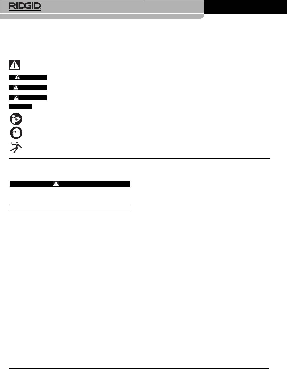
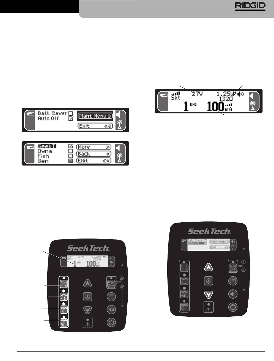
Transmitter Components
Icon Legend
Display Screen
High Voltage Present
Safety Alert
Keypad
Lead Clip
Handle
External Power
Coil Cord (48Ft.
Power ON/OFF
12-15VDC
(16m) Extended)
Shoulder
Inductive Clamp
Strap
Keypad
Display
Screen
Up/Down
Inductive
Arrows
Mode
On/Off
Figure 1 – Top View
Orientation
For
Inductive
Select
Mode
Main
menu
Sound
Frequency
On/Off
Selection
Power
Frequencies
On/Off
High Voltage
Indicator
128Hz
1kHz
Battery
Compartment/
Carriage
Jack For
Inductive
DC Power
8kHz
Clamp
Jack
Figure 2 – Back View
33kHz/
* Top frequency is 262 kHz on Cat. #21903
93kHz or 262kHz*
and 93 kHz on Cat. #21953
Figure 4 – Keypad
Serial Number
Label
Security
Cable Holes
(Can Be Used To Secure
Transmitter With Cable and Lock)
Grounding
Stake
Figure 3 – Bottom View
Ridge Tool Company
5
®
SeekTech
ST-510 Line Transmitter
clockwise to secure the holder in the case. The bat-
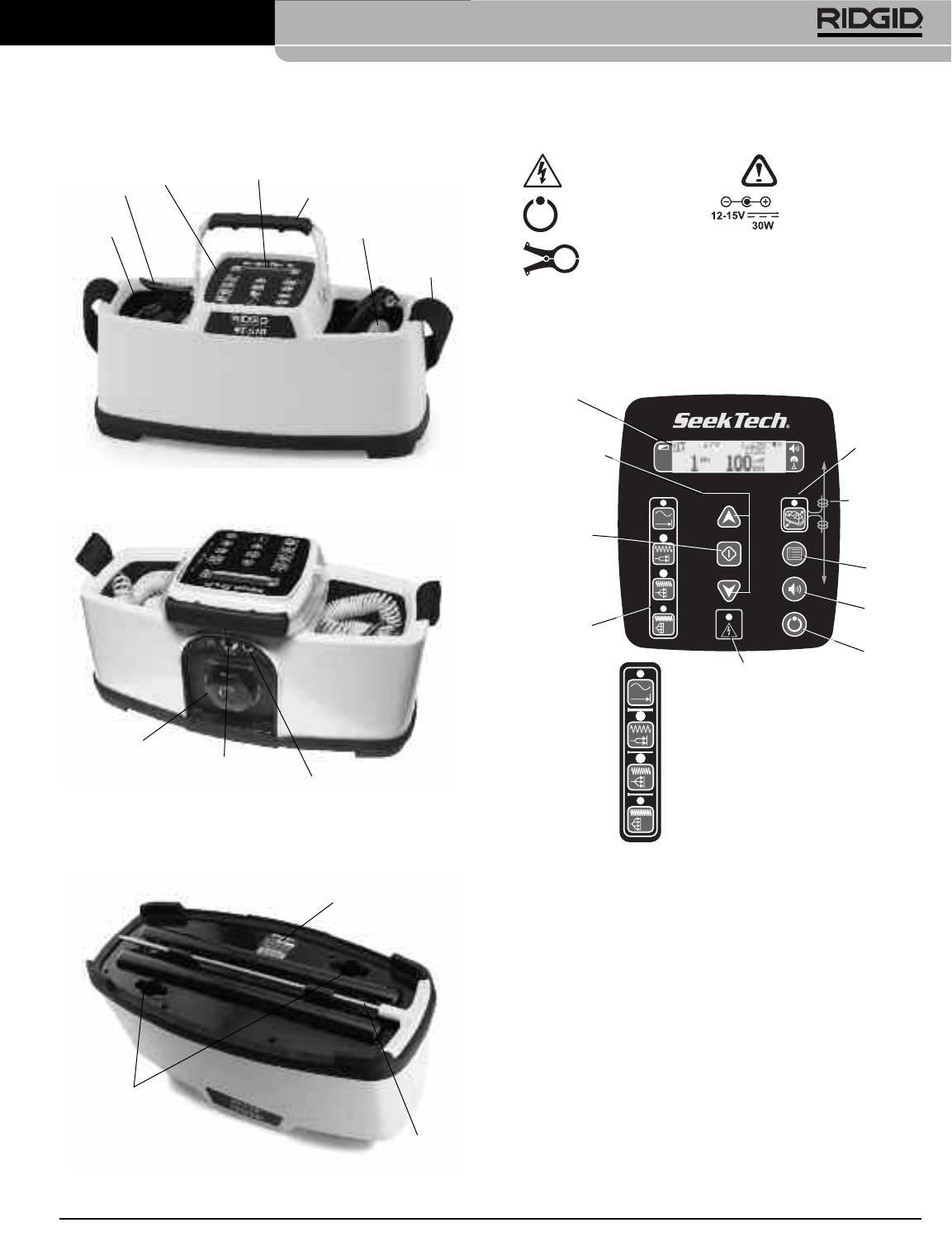
Display Screen
tery holder can be installed in either orientation.
Always remove batteries before shipping unit.
Operation Time
Typical operation time for transmitter with batteries
varies depending on battery type, transmitter settings
(load), backlight use, Battery Saver Mode use, operating
temperature and other factors. When using alkaline
batteries, under average conditions, the batteries will
supply about 12.5 hours of operation. See Estimated
• Battery Level – Shows remaining battery power in 5 steps.
Battery Operating Times Chart for more information.
• Manufacturer – Shows the manufacturer’s frequency set being
used (default is SeekTech).
Estimated Alkaline Battery Operating Times
• Voltage – Voltage that is applied to the leads. This may say MAX,
indicating the voltage is at its highest allowable point (~80 V peak-
Current Est. Time to Depletion
to-peak, ~30V RMS (square wave)).
400 mA 1.8 hours
• Current Strength – current flowing through the circuit in milliamps
200 mA 3.6 hours
(mA).
100 mA 7.25 hours
• Sound – Indicates if sound is ON or OFF.
• Ohms (resistance) – This shows the approximate resistance in
50 mA 14 hours
the circuit.
25 mA 28 hours
• Watts (Power) – Total power that the transmitter is putting out. In
Battery Saver mode, this is absent.
The ST-510 Line Transmitter also includes an auto shut-
• Frequency – Frequency being used.
off feature to help prevent batteries from running down if
the unit is left on inadvertently. Batteries used in high-cur-
rent applicationsmay recover and still be usable if allowed
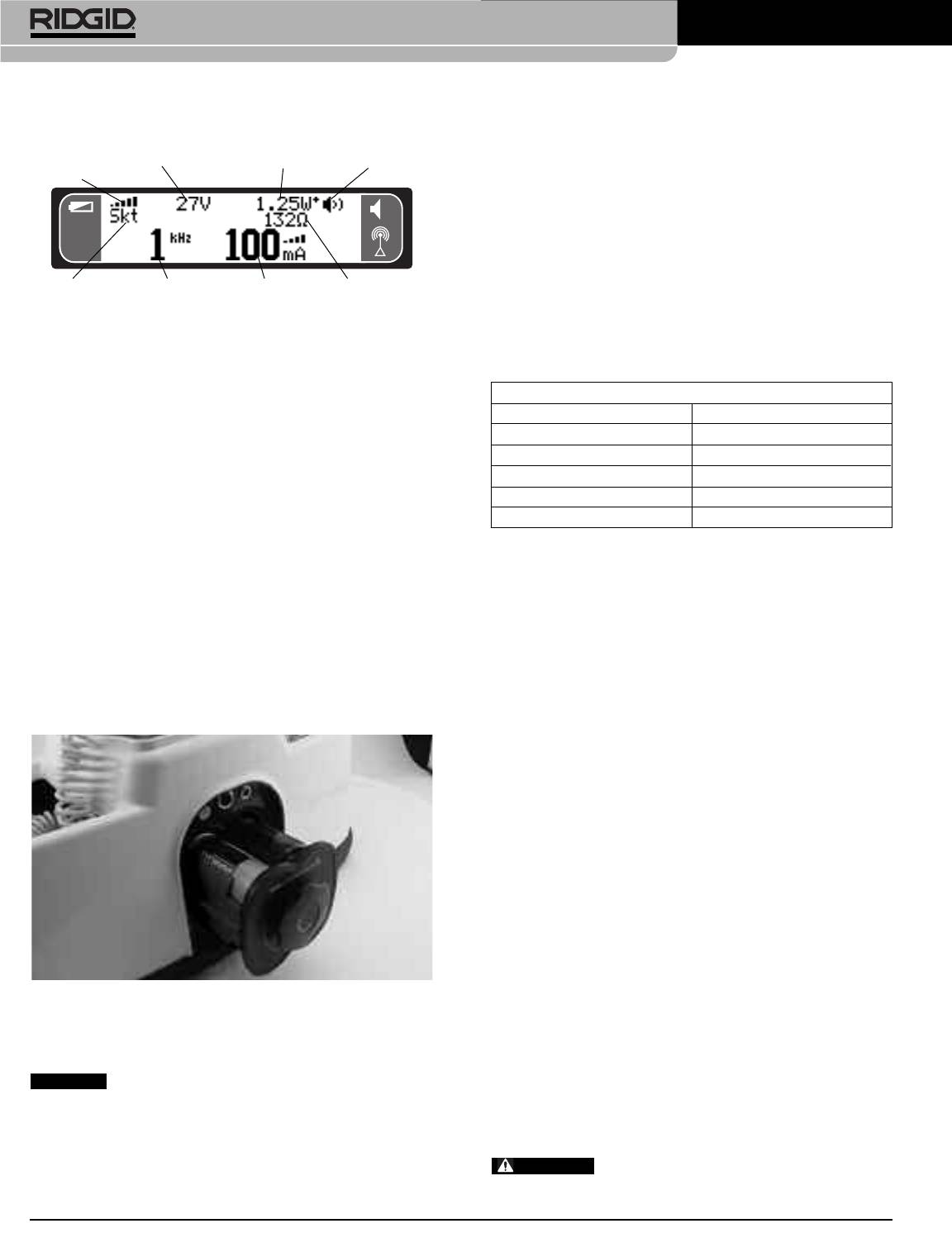
Installing Batteries
to rest prior to being used again.
To install batteries in the ST-510 Line Transmitter, turn
the knob on the battery holder counter clockwise until the
Alternate Power Supply
holder is loose. Slide the holder straight back to re-
move from the transmitter. (See Figure 6.)
1. Using the transmitter with battery power provides the
highest level of electrical isolation and is the recom-
mended power source. However, the Transmitter can
be used with an external power source, such asa ve-
hicle power jack or a standard outlet. In those cases,
the following isolated adapters are recommended.
• Use only a power supply approved to IEC 61010-
1 or IEC 60950. Output must be isolated, SELV
and Limited-Energy Circuit per IEC 61010-1 or
LPS per IEC 60950, 12-15VDC, 30W minimum.
Output connection is standard barrel plug, 2.1mm
pin, tip positive.
NOTE: Adapters are sold separately.
Figure 6 – Removing Battery Holder
If used with an adapter, it is very important that the
above-specified adapter beusedto insure appropriate
Install eight “D” size batteries into the battery holder as
power is supplied to the transmitter. Be sure to read
indicated on the decal on the holder.
and keep the adapter instructions. Make sure the
Use batteries that are all of the same type
adapter cord has a clear, dry path without any poten-
(example – all Alkaline or all NiCd). Do not mix battery
tial source of damage. Use dry hands when plug-
types. Do not mix used and new batteries. Mixing bat-
ging cords in. Do not turn the transmitter on at
teries can cause over heating and battery leakage.
this time.
If the transmitter is used with an external
Fit the battery holder back into the transmitter case and
power source, you must make sure that the external
slide in. Push slightly on the holder and turn the knob
6
Ridge Tool Company
)
)
)
Battery
Voltage
Watts
Sound
Level
Manufacturer Frequency
Current
Ohms
Strength
(Resistance)
Figure 5 – Display Screen
NOTICE
WARNING
®
SeekTech
ST-510 Line Transmitter
power source is fully isolated from ground and power
Set-Up and Operation
mains. If the transmitter is not isolated, the transmitter is
not protected from connection to energized (live) power
WARNING
lines. This could cause electrical shock and damage the
transmitter. Do not use a non-isolated power supply
with the transmitter.
If using the transmitter with a 12V DC adapter from a ve-
hicle power jack on a power line, the vehicle is con-
nected to the power line. If that power line is energized
(live), the vehicle now is at the line voltage, and if the ve-
hicle is grounded, could cause electrical shock or property
Always wear eye protection to protect your eyes
damage to both the transmitter and vehicle.
against dirt and other foreign objects.
Set up and operate the transmitter and work area
according to these procedures to reduce the risk of
Pre-Operation Inspection
injury from electric shock, and other causes, and
prevent transmitter damage.
WARNING
1. Check for anappropriate work areaas indicated inthe
General Safety Section page 2.
2. Inspect the line to have a signal applied to it. The line
must be metal. If the line is not metallic, it will not be
able to be located with this equipment.
When using the transmitter on insulated conductors,
the target conductor should be grounded at each
Before each use, inspect your transmitter and cor-
rect any problems to reduce the risk of serious injury
end. Otherwise, the signal may not be strong enough
from electric shock and other causes and prevent
to locate.
transmitter damage.
The transmitter is not designed to provide high volt-
1. Make sure that the transmitter is unplugged and in-
age isolation and protection. Do not use where a
spect the cords and plug for damage or modification.
danger of high voltage contact is present.
2. Clean any oil, grease or dirt from equipment handles
3. Determine the correct equipment for the application.
and controls. This aids inspection.
Using incorrect equipment for an application can
3. Inspect the transmitter for any broken, worn, missing,
cause injury or damage the equipment.
mis-aligned or binding parts or any other condition
• Equipment for other applications can be found by
which may prevent safe and normal operation.
consulting the Ridge Tool Catalog, online at
www.RIDGID.com or www.RIDGID.eu.
4. Check that the warning label is present, firmly at-
tached and readable.
4. Make sure all equipment has been properly inspected.
5. If any issues are found during the inspection, do not
5. The ST-510 line transmitter can apply an active trac-
use the transmitter until it has been properly serviced.
ing signal to a conductor in three ways:
6. Inspect any other equipment being used per its in-
• Direct Connect – The transmitter’s leads are con-
structions to make sure it is in good usable condition.
nected directly to the target conductor and a suit-
able ground. This method is most commonly used
when the target utility is accessible. Direct con-
nect should not be used for energized (live) con-
ductors.
• Inductive Clamp (optional accessory) – the jaws of
the inductive clamp encircle the target conductor; if
the conductor is insulated, there is no metal to
metal contact. This method is commonly used
when the target utility is accessible but direct con-
nect is not possible on an insulated cable for ex-
ample. (See Page 9)
Ridge Tool Company
7
®
SeekTech
ST-510 Line Transmitter
• Inductive Mode – The transmitter generates a field,
4. Scrape away any dirt, paint, corrosion or other coat-
which in turn induces a current in the target con-
ings on the target conductor to insure good contact
ductor. There is no direct connection between the
with the cable lead. Again, this lowers the resistance
transmitter and the target conductor. The trans-
of the circuit and results in a stronger tracing signal.
mitter is placed over and inline with the target con-
Connect the other cable lead to the target conductor.
ductor. The transmitter’s internal antenna induces
(See Figure 8).
a signal onto the target conductor. This method is
most commonly used when the target utility is not
accessible. (See page 9).
Direct Connect Method
1. Confirm that the target conductor is NOT energized
(live). The transmitter is not designed to be con-
nected to energized (live) conductors.
2. Choose ground spike and target conductor connec-
tion locations. The cable leads extend up to 48 feet to
give flexibility in choosing connection points. The
Figure 8 – Connecting Cable Lead To Target Conductor.
cords of the transmitter can act as antennas, and the
further they are extended, the more incidental signal
5. Press the POWER ON/OFF button on the keypad to
they can send out. The further the leads are ex-
turn the transmitter on. As the power comes on, the
tended, the further the receiver should be used from
transmitter will emit ascending beeps. The transmitter
the transmitter to avoid misleading signals from the
will pause to measure how much current is flowing
cords. If locating close to the transmitter, keep the
onto the target conductor. The faster the beeping, the
leads as short as possible with the excess in the
higher the detected current. To turn the beeping off,
transmitter’s side pockets.
press the sound key. (See Figure 4).
WARNING
The line transmitter is designed to with-
stand up to 240V AC between the two leads. The pro-
tection is NOT intended to be used continuously. If the
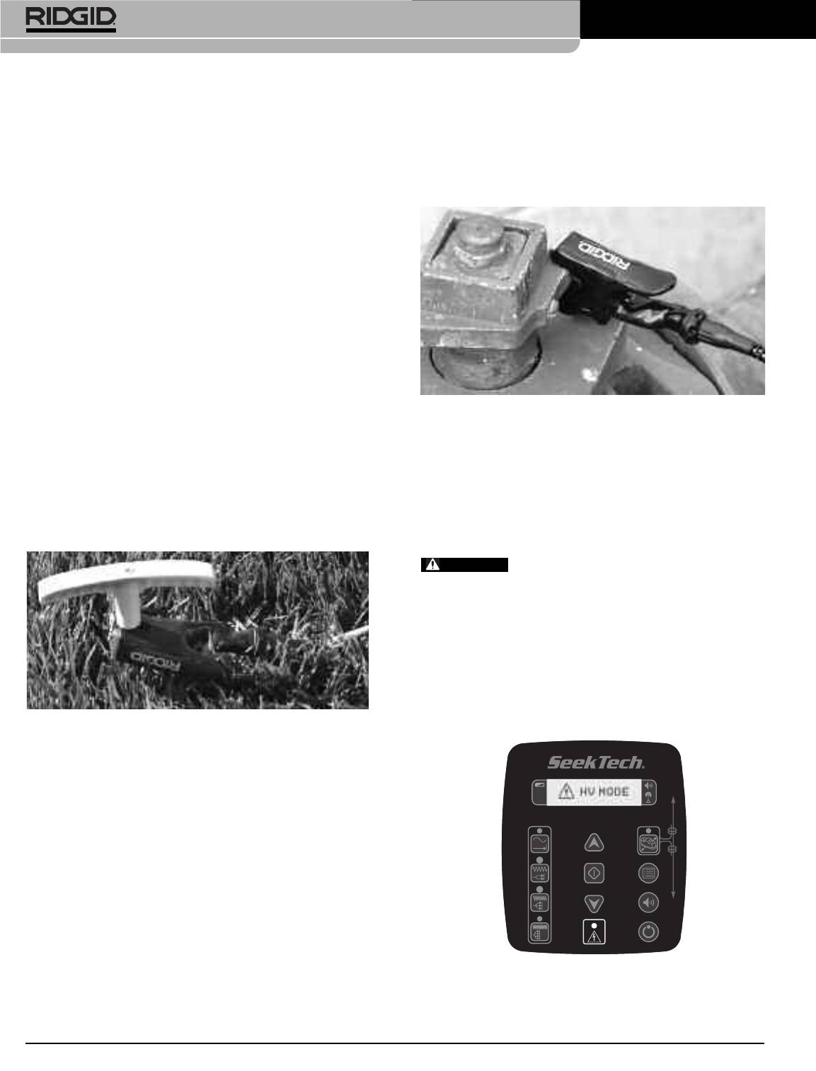
transmitter encounters a target conductor voltage higher
than approximately 42 volts (RMS), a red LED next to the
High Voltage Present Indicator will flash and the LCD
screen will display the safety alert symbol and “HV MODE”
(See Figure 9). If this happens, DO NOT TOUCH THE
TRANSMITTER, CORDS OR CONNECTIONS. The tar-
get conductorisenergized and there isthe risk of electrical
Figure 7 – Attaching Lead To Ground Stake
shock. Use high voltage precautions to disconnect.
3. Remove the ground spike from the bottom of the
transmitter and insert it into the earth. A good ground
results in a stronger tracing signal. To get a good
ground, insert the ground spike as far as possible into
the earth. Moist earth will give a better ground than
dry earth. Wetting the earth around the ground spike
can improve grounding. This lowers the resistance of
the circuit. Connect either cable lead to the ground
stake. Always connect to the ground first. Ifthe tar-
get conductor has an unknown voltage on it, this
may allow the current to be directed away from the
user. (See Figure 7).
Grounding can also be accomplished by attaching the
Figure 9 – High Voltage Indicator
cable lead to things like shovel blades or larger rods
sunk into the earth. These can improve grounding by
increasing area/depth in contact with the Earth.
8
Ridge Tool Company
®
SeekTech
ST-510 Line Transmitter
6. Select a frequency, check the circuit and adjust cur-
rent. See pages 10 and 11 for more information.
7. Turn onthe receiver/locator and follow the instructions
for the receiver. Make sure the receiver’s frequency is
set to match that on the transmitter. Confirm the re-
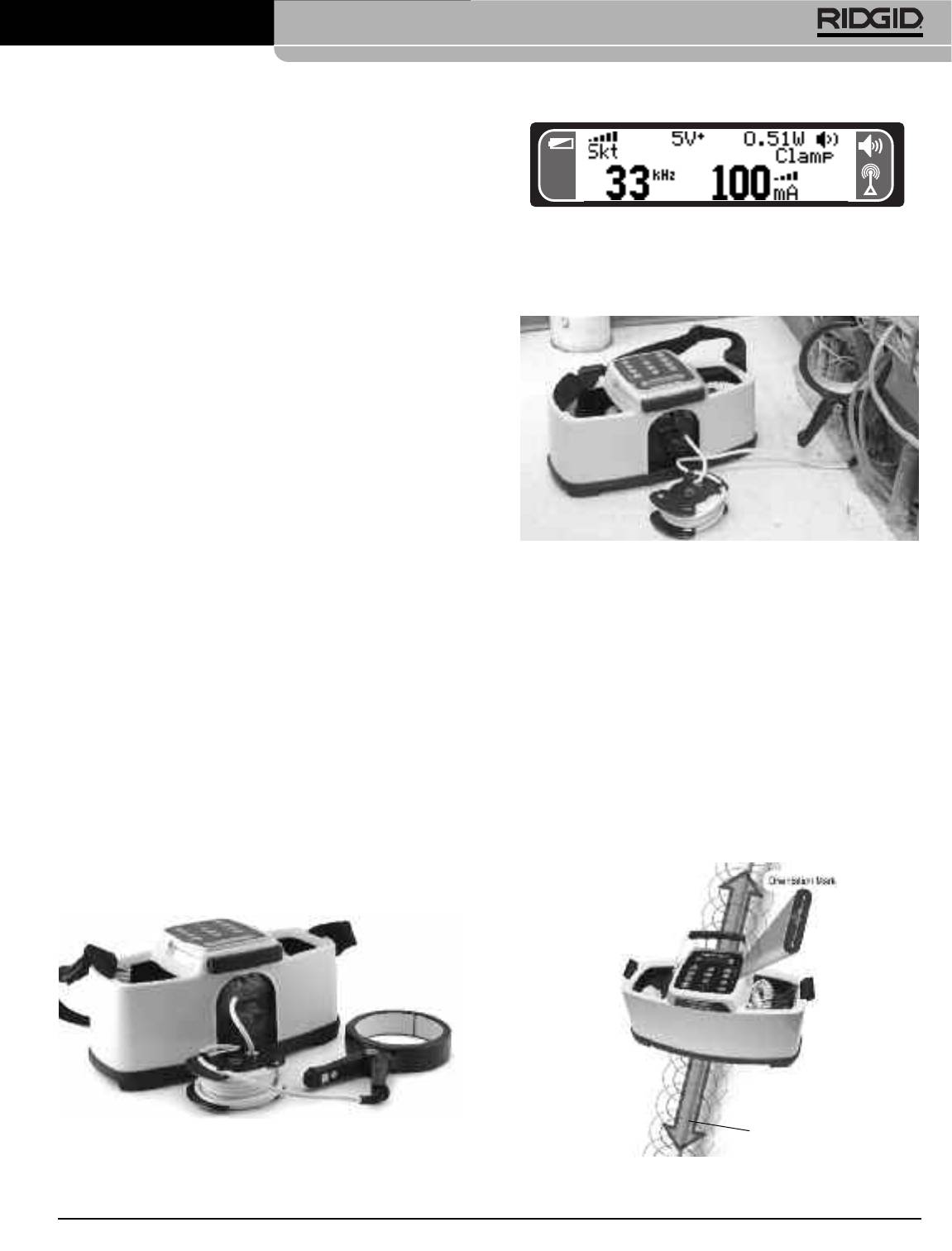
Figure 11 – Transmitter In Inductive Clamp Mode
ceiver is picking up the transmitted frequency by
holding it near the transmitter and observing the in-
5. Clamp the jaws of the inductive clamp around the tar-
crease in receiver signal.
get conductor. Make sure that the jaws of the clamp
are fully closed. (See Figure 12).
8 Once the locating is completed, press the POWER
ON/OFF button on the keypad to turn the transmitter
off. Always turn the unit off before disconnecting
the cable leads to reduce the risk of electrical
shock. Remove the cable lead from the target con-
ductor first. Always disconnect the cable lead fromthe
target conductor first before removing the cable lead
from the ground spike to reduce the risk of electrical
shock. Disconnect the cable lead from the ground
spike. Store the cables and ground spike for trans-
portation.
Inductive Clamp Method
Figure 12 – Inductive Clamp Attached to a Conductor
1. This method requires an inductive clamp that is not
supplied with the transmitter. Read and follow all in-
6. Turn the transmitter on and select a frequency for lo-
struction for the use of the inductive clamp.
cating, check the circuit and adjust current. (See
page 11). Be sure that the receiver is set to the same
2. Confirm that the target conductor is NOT energized
frequency. The inductive clamp typically works best
(live). The transmitter is not designed to be con-
with frequencies around 33 kHz.
nected to energized (live) conductors.
7. Once locating is complete, turn the transmitter power
3. Confirm that the transmitter is OFF. If needed, press
OFF before disconnecting the clamp.
the POWER ON/OFF button on the keypad to turn
thetransmitteroff.Never turn the transmitter onbefore
Inductive Mode
attaching the inductive clamp.
1. Properly place the transmitter relative to the target
4. Insert the plug of the inductive clamp into the jack on
conductor. On the top of the transmitter is an orien-
the transmitter (above the battery holder). When the
tation mark. The orientation mark needs to be aligned
inductive clamp plug isin place,the transmitter willau-
with the target conductor. (See Figure 13).
tomatically be in Inductive Clamp mode, the cable
leads will be disabled, and “Clamp” will be displayed
on the screen. (See Figure 11).
Figure 10 – ST-510 with Inductive Clamp
Target
Conductor
Figure 13 – Orientation to the Line – Inductive Mode
Ridge Tool Company
9
®
SeekTech
ST-510 Line Transmitter
2. Press the POWER ON/OFF button on the keypad to
at least 30 feet from the transmitter to prevent this.
turn the transmitter ON. As the power comes on, the
(See Figure 15).
transmitter will emit ascending beeps. Press the
One way to confirm that you are tracing the target
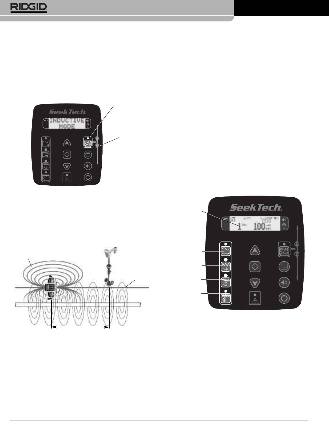
Inductive Mode Key. The display screen will read “IN-
conductor and not the transmitter field is to look for a
DUCTIVE MODE”. (See Figure 14). The transmitter
strong, stable proximity signal and a valid depth mea-
will make a short buzzing sound when shifting into
surement on the receiver. While directly over the en-
Inductive Mode, and after that,will make double beeps
ergized line you can also raise the receiver a set
during inductive mode operation. If desired turn the
distance off of the ground, and verify that the depth
beeping off by pressing the sound key (SeeFigure 4).
reading on the display equals the distance that you
Inductive Mode
Key
raised the receiver.
5. Once the locating is completed, press the inductive
mode key again toexit inductive mode, then pressthe
POWER ON/OFF button on the keypad to turn the
Orientation
transmitter OFF.
Mark
Selecting A Frequency
Select a frequency for locating by pressing a frequency
key on the keypad (See Figure 16). The frequency will be
shown in the display. For 262 kHz, press the 33 kHz key
twice. (In European versions, this will set the frequency to
Figure 14 – Inductive Mode Key
93 kHz.) The frequency selected will show on the display.
3. Select a frequency as described in thismanual. When
Frequency
using Inductive Mode, higher frequencies tend to get
Selected
a better signal at the receiver.
4. Turn on the receiver/locator and follow its instruc-
tions. Make sure to set the receiver to the same fre-
quency as the transmitter.
Transmitter
128Hz
Field
1kHz
Induced Field
On Target
Conductor
8kHz
33kHz/93kHz
or 262kHz
Figure 16 – Frequency Display
Target
Conductor
30 Feet Minimum
It is usually best to use the lowest frequency needed to in-
Figure 15 – In Inductive Mode, Locate At Least 30 Feet
duce a signal on the target conductor. Lower frequencies
From Transmitter To Insure Tracing Target
usually travel farther. Higher frequencies generally make
Conductor
it easier to induce a signal on the target conductor but are
more likely to cause signals on adjacent, non-target con-
When the transmitter is in inductive mode, itgenerates
ductors causing distortion and reducing accuracy.
a field around the transmitter. This field is in both
The default ST-510 frequency settings are for use with a
the ground (towards the target conductor) and into the
RIDGID receiver/locator. If using another manufacturer’s
air around the transmitter. When the receiver is within
receiver compatible frequencies will need to be loaded.
approximately 30 feet (10 meters) of the transmitter,
TheST-510 transmitter has theappropriate frequencies for
it will measure the field directly from the transmitter
a variety of other receiver/locator units available by using
and not the signal induced on the target conductor.
the manufacturer menu in the main menu. For available
This is called “Air Coupling”. Operate the receiver
10
Ridge Tool Company
manufacturers and frequencies, see the Manufacturers
Check The Circuit
Frequency Table on page 16. Consult your re-
Look at the resistance (Ω - ohms), the voltage (V) and
ceiver/locator operator’s manual or manufacturer for more
the current (mA) displayed on the screen (See Figure
information on those products.
20). Display numbers are approximate. Generally the
To load other manufacturers frequency information
lower the ohms (total resistance) the more efficiently
• Press the menu key (Figure 4).
current can be added. Lower total resistance indicates an
efficient circuit and requires less voltage to induce a
• Use the UP/DOWN keys to scroll to “Manf. Menu”
signal in the line.
and press the select key. This will bring up the list of
manufacturers. (Figure 17).
• Use the UP/DOWN keys to scroll to the appropriate op-
tion and press the select key. (Figure 18).
Figure 20 –Display Panel
The transmitter will beep faster if the resistance is lower
Figure 17 – Manufacturers Menu Selection
and slower if the resistance is higher.
Adjust Current
Use the up and down keys to adjust the amount of cur-
rent in milliamps (mA) (Figure 21).
More current gives a stronger signal. Less current pro-
Figure 18 – List of Manufacturers (First Screen)
longs battery life. Signal strength measured by the re-
ceiver is directly proportional to the amount of current on
When using the frequency keys while set up for a dif-
the line. More current means a stronger signal will be re-
ferent manufacturers receiver/locator, the lowest fre-
ceived by the receiver.
quency is controlled by the top (closest to the readout)
frequency key. The frequency moves higher with
To prolong battery life and reduce the chance of the sig-
each key further away from the readout. If there are
nal “bleeding over” onto adjacent lines, use the minimum
more than four frequencies, pushing the frequency
amount of current needed to get a clear reading on the
key furthest from the readout multiple times will in-
receiver.
crement the frequency to the next higher frequency.
(See Figure 19.) As always, the frequency selected is
displayed on the readout.
Figure 21 – Current Selection (Up and Down Keys)
There are 7 current levels that the user can choose
from: 5, 25, 50, 100, 200 or 400 mA.
Figure 19 – Frequency Buttons – Other Manufacturer
Receiver/Locator
))
))
))
))
))
))
Frequency
Selected
Low
Med Low
Med High
HIgh
))
))
))
®
SeekTech
ST-510 Line Transmitter
Resistance
Voltage
Current
Ridge Tool Company
11
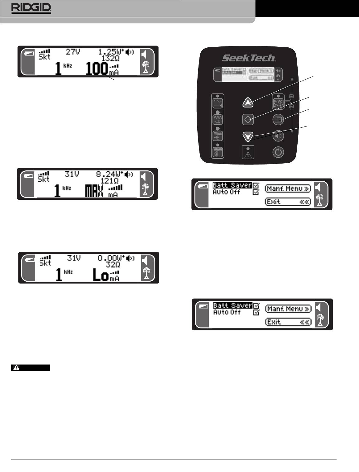
Figure 22 – Current Selected
When a current level is chosen, the transmitter will adjust
the voltage to try and produce the selected current and
lock it in. If the transmitter cannot produce the current se-
lected, it will adjust down to the next level.
The transmitter’s maximum current output depends on
the amount of resistance in the circuit. When the trans-
mitter is putting out the maximum current possible for in-
ternal and external conditions, MAX will be displayed in
place of the current strength number.
Figure 25 – Menu, Up and Down and Select Keys
Figure 23 – MAX Current
Figure 26 – Main Menu Choices
MAX will also appear if the power output of the trans-
mitter is at its allowable limit.
To accept the highlighted choices, press the select key.
When the current drops below 5 mA, “LO” will appear in-
stead of a number.
Battery Saver Mode
This allows the user tolimit thepower output of the ST-510
line transmitter to approximately 1 watt in order to prolong
the life of the batteries. In many cases 1 watt of power is
all that is needed. Using the unit with up to 10 watts allows
for more power to be used, but consumes the batteries
Figure 24 – LO Current
much faster. Battery Saver is off by default.
If the desired current output cannot be produced, the volt-
age and ohms (resistance) readings can give useful in-
formation. For example, if the transmitter is putting out a
high voltage, the resistance of the circuit is probably
too high. If the voltage is lower (30V max) and the ohms
Figure 27 – Battery Saver and Auto-Off Options
(resistance) reading is also low, the line transmitter may
be constrained by power restrictions. (See FCC limits in-
Auto Shut Off Adjustment
formation on page 4.)
Check this box to have an automatic shut OFF of the
If the transmitter is showing low or no
transmitter. When checked, using the select key, the ST-
current, the signal may be too low to be detected by
510 will automatically shutdown to help conserve batter-
the receiver locator and inadequate for tracing.
ies. Shutdown time using this feature varies with current
draw. The approximate values are:
Main Menu
8 hrs 25mA output or less
To access the main menu, press the menu key (See
4 hrs 50-100mA
Figure 25). The Up and Down keys can be used to scroll
2 hrs 200-400mA
through the main menu choices (See Figure 26) in either
1hr >400mA
direction.
This feature prevents the batteries from running down if
the unit is inadvertently left on. Auto Shutoff is on by de-
fault. (See Figure 27).
))
))
))
))
))
))
Up Key
Down Key
))
))
))
Select Key
Menu Key
))
))
))
WARNING
))
))
))
®
SeekTech
ST-510 Line Transmitter
Current
12
Ridge Tool Company
®
SeekTech
ST-510 Line Transmitter
Auto Back Light
Cleaning Instructions
The SeekTech is equipped with an automatic LCD back-
light. Whenever a key is pressed, the backlight is acti-
WARNING
vated to aid viewing for 80 seconds.
Remove batteries before cleaning.
Adjusting the LCD Screen Contrast
1. Keep the ST-510 line transmitter clean with a damp
cloth and some mild detergent. Do not immerse in
LCD contrast is set at the factory and should not normally
water.
require adjustment. Optimal contrast is set when the
background remains white, while the black pixels are set
2. When cleaning, donot use scraping tools or abrasives
to be as dark as possible.The LCD can be adjusted to
as they may permanently scratch the display. NEVER
completely white or completely black, which will affect
USE SOLVENTS to clean any part of the system.
readability.
Substances like acetone and other harsh chemicals
can cause cracking of the case.
LCD contrast may change with extremes in tempera-
ture. When the screen is exposed to high heat from direct
sunlight it may darken. It is recommended that the screen
Accessories
be shaded if it is to beexposed to excessive sunlight. Use
the shoulder strap to cover the screen if needed.
WARNING
If the display appears too dark or too light when it is on, it
The following accessories have been designed to
function with the ST-510 line transmitter. Other ac-
is likely that the LCD contrast has become misadjusted.
cessories suitable for use with other equipment
First try powering the unit OFF and then back ON. If the
may become hazardous when used with the ST-
problem persists adjust the LCD contrast darker or lighter
510 line transmitter. To reduce the risk of serious in-
as needed.
jury, only use accessories specifically designed and
recommended for use with the ST-510 line trans-
To adjust the LCD Contrast:
mitter, such as those listed below.
1. Press and hold down the select key.
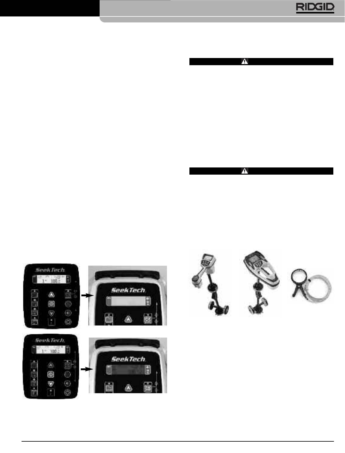
• Receivers: RIDGID SeekTech SR-20 (Cat#21893),
or SR-60 (Cat#22163)
2. Simultaneously press the up arrow key to lighten
• Inductive Clamp (Cat# 20973)
the display or press the down arrow key to darken the
display.
SR-20 SR-60
Inductive Clamp
Figure 28 – Adjusting LCD Contrast
Ridge Tool Company
13
®
SeekTech
ST-510 Line Transmitter
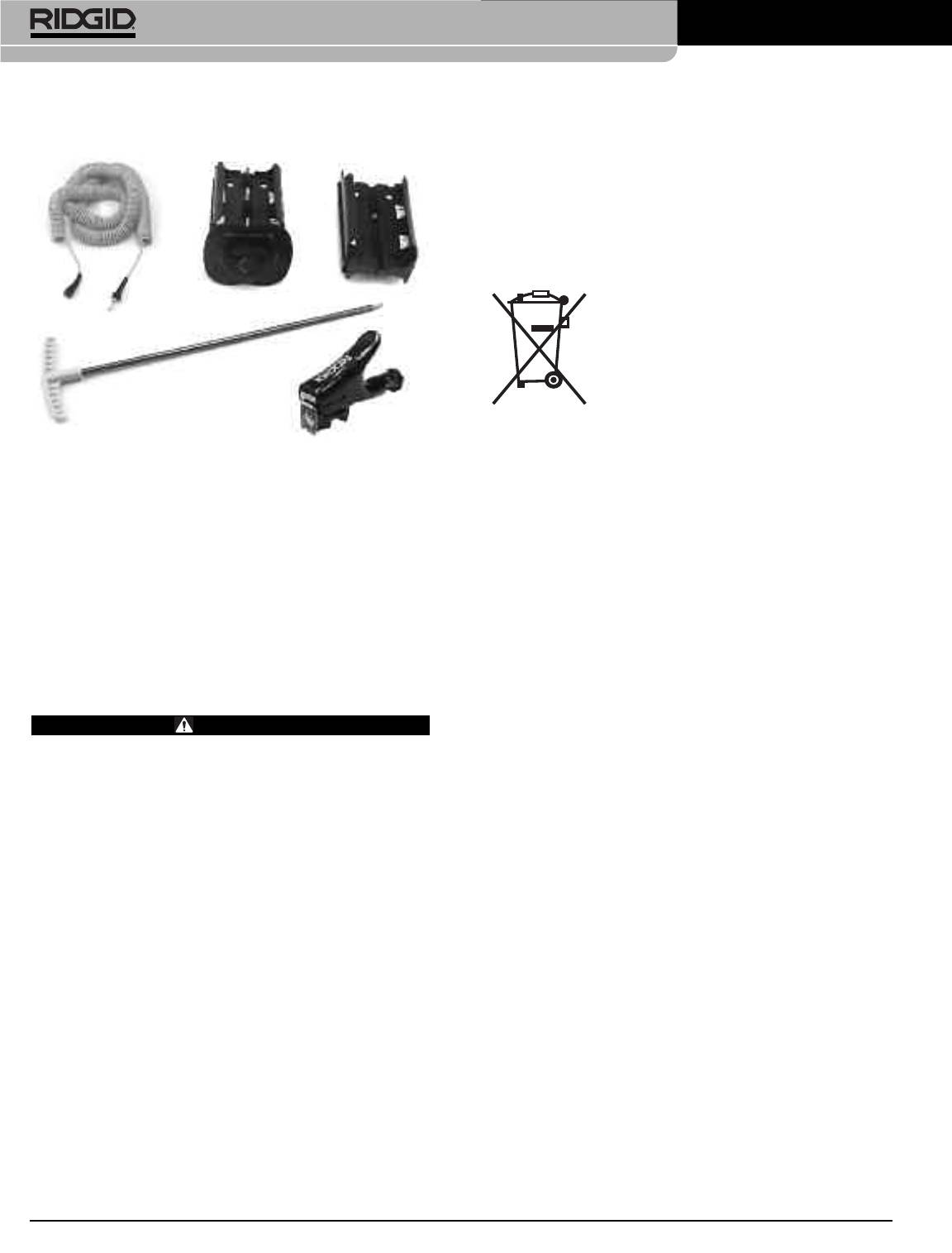
Replacement Parts
Disposal
Parts are available from your local RIDGID Distributor.
Parts of the SeekTech ST-510 Line Transmitter contain
A
CB
valuable materials and can be recycled. There are com-
panies that specialize in recycling that may be found lo-
cally. Dispose of the components in compliance with all
applicable regulations. Contact your local waste man-
agement authority for more information.
For EC countries: Do not dispose of elec-
trical equipment with household waste!
D
According to the European Guideline
2002/96/EC for Waste Electrical and
E
Electronic Equipment and its implemen-
tation into national legislation, electrical
equipment that is no longer usable must be collected
separately and disposed of in an environmentally correct
A. Direct Connect Lead(48ft./16m) (Cat. #18423)
manner.
B. Battery Holder Cover Assembly (Cat. #18428)
C. Battery Holder (Cat. #18433)
D. Ground Spike (Cat. #18438)
E. Direct Connect Lead Clip (Cat. #18443)
Transport And Storage
Remove batteries before shipping. Do not expose to
heavy shocks or impacts during transport. If storing for an
extended period, remove batteries. Store in environments
withintemperature range of14°Fto 158°F(-10°Cto 70°C).
Service And Repair
WARNING
Improper service or repair can make machine un-
safe to operate.
Service and repair of the SeekTech ST-510 must be per-
formed by a RIDGID Independent Authorized Service
Center.
For information on your nearest RIDGID Independent
Service Center or any service or repair questions:
• Contact your local RIDGID distributor.
• Visit www.RIDGID.com or www.RIDGID.eu to find
your local Ridge Tool contact point.
• Contact Ridge Tool Technical Services Department at
rtctechservices@emerson.com, or in the U.S. and
Canada call (800) 519-3456
14
Ridge Tool Company

®
SeekTech
ST-510 Line Transmitter
Chart 1 Troubleshooting
PROBLEM POSSIBLE REASONS SOLUTION
Receiver will not pick up
The Receiver and the Transmitter may not be on
Check that the correct frequency has been se-
the line transmitter’s
the same frequency.
lected on both units (See manual for the specific re-
signal.
ceiver). Higher or lower frequencies may be tried.
The receiver may not be in the correct mode.
Make sure that the proper functions are activated on
the receiver. e.g. activating the line trace function for
line tracing (See manual for the receiver).
Inadequate grounding.
Ensure grounding is adequate.
Power output may need to be increased.
Adjust power output upward if possible.
LCD appears completely
LCD may need to be reset.
Try Powering the unit OFF and then back ON.
dark, or completely light
Unit may be overheated.
Allow the unit to cool if it has been exposed to ex-
when unit is ON.
cessive heat from sunlight.
Unit will not turn ON.
Batteries may not be properly oriented.
Check orientation of batteries.
Batteries may be dead.
Check that the batteries are fresh or charged.
Battery Contacts may be broken or bent.
Inspect battery contacts.
93 kHz signal not
Receiver is not set to the correct 93kHz frequency.
Change transmitter frequency to 93696 Hz by se-
received.
lecting RIDGID-Old on manufactures menu.
Check that receiver is set to the actual 93kHz
frequency of 93,622.9 Hz. Some receivers use a
different frequency for 93 kHz (93,696). Update
SeekTech receiver software.
Ridge Tool Company
15

®
SeekTech
ST-510 Line Transmitter
Frequencies
Exact Frequencies per Band (In Hz)
128 Hz 1kHz 8kHz 33kHz 93kHz* 262kHz
Default Line 128 1024 8192 32768 93623 262144
(SeekTech)
*(European
(European
Model Only)
Model Limited
To 93kHz)
Manufacturers Frequency Table
Displayed
Available
Exact
Company
Model
Notes
Manufacturer Frequencies Frequency (Hz)
577Hz 577
200 KHz not present
Dyna 3M Dynatel™ 8kHz 2273 8192
in European model of
33kHz 32768
the ST-510.
200kHz 200012
820Hz 821
Fish FISHER 8.2kHz TW-8800 8217
82kHz 82488
512Hz 512
Gen Gen-Eye™ 8kHz LCTX 512/8/65 8192
65kHz 65536
Not recommended for
use with the ST-510
transmitter.
Gold GOLDAK 117.5kHz 3300 117500
Not present in
European model of
the ST-510.
Heath 8.1kHz 8128
480 KHz not present
Heath Consultants 81kHz ALLPRO 81326
in European model of
Incorporated 480kHz 480323
the ST-510.
®
9.5kHz
9499
Made by Takachiho
McLau McLAUGHLIN
VERIFIER
38kHz 37997
Sanyo Co., Ltd.
982Hz 982
®
9.8kHz 9890 9820
Metro METROTECH
82kHz 810 for 83kHz 82488
83kHz 83080
MicroE Microengineering 76.8kHz Xmtr-101 76802
Mytan MyTana 76.8kHz PT20 76802
Not present in
Phorn PipeHorn 480kHz 479956
European model
of the ST-510.
512Hz 512
Radio Detection 8kHz
8192
(Same as
200 kHz not present in
(Same as 33kHz
32768
RD
LCTX 512/8/65
European model of the
Gen-Eye™ 65kHz
65536
above)
ST-510.
above) 82kHz 81865
200kHz 200000
16
Ridge Tool Company

®
SeekTech
ST-510 Line Transmitter
Manufacturers Frequency Table (continued)
Displayed
Available
Exact
Company
Model
Notes
Manufacturer Frequencies Frequency (Hz)
512 512
8kHz 8192
200k changed to
®
RIDGID
(Old) Ridge Tool Co. 33kHz 32768
93kHz in European
51kHz 51712
model of the ST-510.
200kHz 200000
128 Hz 128
1 kHz 1024
®
262k changed to
RIDGID
(New) Ridge Tool Co. 8 kHz 8192
93kHz in European
33 kHz 32768
model of the ST-510.
93 kHz 93623
262 kHz 262144
128 Hz 128
1 kHz 1024
RIDGID-B (New) Ridge Tool Co. 8 kHz 8192
33 kHz 32768
93 kHz 93696
815Hz
815
Ryco RYCOM
8876
82kHz 82318
SeekTech-B 128 Hz 128
1kHz 1024
8kHz 8192
33kHz 32768
93kHz* 93696
* 93 kHz on European
262kHz 262144
model Only
Schonstedt
Schon Instrument 575Hz TraceMaster 575
Company
8kHz
8055
Ssurf SubSurface
PL-2000
Made by FUJI TECOM
27kHz 26721
®
SubS SUBSITE
1kHz 1170
ELECTRONICS 8kHz 950 8009
Ditch Witch® 29kHz 29430
80kHz 80429
Telex 577Hz 577
Ridge Tool Company
17

®
SeekTech
ST-510 Line Transmitter
18
Ridge Tool Company


