Ridgid SeeSnake Compact: инструкция
Раздел: Электроинструменты
Тип:
Инструкция к Ridgid SeeSnake Compact

SeeSnake
Flatpack/
Compact
GB p. 1
DE p. 6
FR p. 11
NL p. 16
IT p. 21
ES p. 26
PT p. 31
SV p. 36
DA p. 41
NO p. 46
FI p. 51
HR p. 56
PL p. 61
RO p. 67
CZ p. 72
HU p. 77
GR p. 82
RU p. 88
Figures p. 95
RIDGE TOOL COMPANY

SeeSnake Flatpack/Compact
Service
1. Tool service must be performed only by qualifi ed repair personnel.
GB
Service or maintenance performed by unqualifi ed repair personnel could
result in injury.
2. When servicing a tool, use only identical replacement parts. Follow
SeeSnake Flatpack/Compact
instructions in the Maintenance Section of this manual. Use of
unauthorized parts or failure to follow maintenance instructions may
create a risk of electrical shock or injury.
Operating Instructions
3. Unplug this product from the wall outlet, remove the battery and refer
servicing to qualifi ed service personnel under any of the following
conditions:
WARNING! Read these instructions
a) When the power cord or plug is damaged;
and the accompanying safety booklet
b) If liquid has been spilled onto, or objects have fallen into the product;
carefully before using this equipment. If
c) If product does not operate normally by following the operating
you are uncertain about any aspect of using this
instructions;
tool, contact your RIDGID distributor for more
d) If the product has been dropped or damaged in any way;
e) When the product exhibits a distinct change in performance.
information.
In any correspondence, please give all the information shown on the nameplate
Failure to understand and follow all instructions
of your tool including model number, voltage and serial number.
may result in electric shock, fi re, and/or serious
personal injury.
Specifi c Safety Information
READ THIS OPERATORS MANUAL CAREFULLY BEFORE USING THE
PRODUCT.
SAVE THESE INSTRUCTIONS!
Failure to understand and follow the contents of this manual may result in
Electrical Safety
electric shock, fi re and/or serious personal injury. Contact your distributor if
Tool is only splash resistant when the Monitor Shield is in place. Avoid
you have any questions. Read and follow the safety labels on the equipment!
prolonged exposure to rain or wet conditions. Water entering a power
Know the location and functions of all controls before using system.
tool will increase the risk of electrical shock. Keep battery out of direct
contact with water. Protect AC adapter from damp or wet conditions.
Tool Safety
1. Extension cords are not recommended unless they are plugged into
Battery Precautions
a Ground Fault Circuit Interrupter (GFCI) found in circuit boxes or
1. Use only the size and type of battery specifi ed.
receptacles.
2. Be sure to install the battery with the correct polarity as indicated in the
2. Do not place the unit in water. Water entering the housings will increase
battery compartment.
the risk of electrical shock.
3. Recharge batteries with charging units specifi ed by the battery
3. Only the camera head and cable are waterproof. The monitor is splash
manufacturer. Using an improper charger can overheat and rupture the
resistant only when the Monitor Shield is covering the monitor screen
battery.
and the unit is operating under battery power. Do not expose AC adapter
4. Properly dispose of the battery. Exposure to high temperatures can
to damp conditions. The monitor should not be exposed to moderate or
cause the battery to explode, so do not dispose of in a fi re. Some
heavy rain or placed in standing water.
countries have regulations concerning battery disposal. Please follow all
4. CAUTION! Camera head can get HOT! Turn OFF camera when not in
applicable regulations.
use.
Personal Safety
SAVE THESE INSTRUCTIONS!
Make sure the pipe you are going to inspect is not electrically charged, or
“hot”! In some cases ground circuits may be returned to cast iron pipes
causing them to be electrically charged. If you have any reason to suspect
Description, Standard Equipment and Specifi cations
the pipe is “hot”, have it checked by a qualifi ed electrician before putting
Description
the camera in the line. As sections of pipe joined with shielded hubless
The SeeSnake Flatpack/Compact pipe inspection system comprises a
connections or compression gaskets may be electrically isolated, care should
camera head and push cable enclosed in a molded drum, and a splash
be taken to check the entire length of any pipe you are going to inspect.
resistant camera control unit (CCU). The CCU has a built-in high-resolution
B&W or color monitor and can be powered from its included AC adaptor or
Tool Use and Care
from an optional rechargeable battery. The SeeSnake Flatpack/Compact pipe
1. Always transport the SeeSnake Flatpack/Compact with the Monitor
inspection camera is ideal for inspecting 40 to 150 mm drain lines. Its spring
Shield closed.
mounted camera head can negotiate multiple hard 90° (50 mm) bends and its
2. Do not use the tool if the switch does not turn it ON or OFF. Any tool that
push cable is fl exible enough to easily travel through bends, yet stiff enough to
cannot be controlled with the switch is dangerous and must be repaired.
push the camera head up to 30 m.
Included with the SeeSnake Flatpack/Compact is a 512 Hz transmitter
to locate the exact location of the problem. Like all SeeSnake systems,
the SeeSnake Flatpack/Compact has been engineered and tested to ensure
Ridge Tool Company
1

SeeSnake Flatpack/Compact
rugged and reliable operation on the kinds of jobs you encounter every day.
Locking Sleeve - Found at the end of the Interconnect Cable (Figure 1), it
The SeeSnake Flatpack and Compact drum is available with B&W or color
provides a solid connection between the CCU and the reel.
camera head. The monitor is available with a B&W monitor or color monitor.
NOTE: When attaching or removing the Interconnect Cable from the
System Components
CCU, turn only the locking sleeve! Bending or twisting the connectors
The SeeSnake Flatpack/Compact pipe inspection system contains the
inside the locking sleeve will lead to premature failure.
following three sub assemblies: Camera Head, Drum, and Camera Control Unit.
Please take a moment to learn the functions of each of these components.
3. Camera Control Unit (CCU)
This unit provides power to the camera reel, control of the camera’s light
1. Camera Head
intensity and a built-in B&W/ color monitor for viewing the image.
The camera head has adjustable lighting elements and a highly scratch
®
The CCU may be powered by any 230 volt AC source or an optional Makita
resistant sapphire window (Lens Port). This coupled with the stainless steel
rechargeable battery. Battery 14,4V: catalog 83407. Charger 230V for battery:
armoring allows the camera to withstand repeated battering in cast iron pipes.
84112.
The Camera is rated to a water depth of 100 m.
For the SeeSnake Compact, the monitor can be left mounted on the frame or
removed to improve your view of the monitor system.
LED - Light Emitting Diode. Solid-state light that, unlike an incandescent lamp,
does not have a fragile fi lament. The B&W SeeSnake Flatpack/Compact uses
Monitor Shield – Protects the monitor and internal electronics from moisture
red LED’s. The color Flatpack/Compact uses bright white LED’s.
such as light rain (Figure 2A).
LED Window -The polycarbonate donut shaped ring that covers and protects
Tilt Stand – The front handle attached to the monitor shield also acts as a tilt
the LEDs from abrasion.
stand for positioning the monitor at a better viewing angle (Figure 2B).
Spring Assembly - Flexible stainless steel spring and associated components
Red Multifunction Button (Figure 3) – This button serves the following
that hold the camera to the push cable. It provides a fl exible transition from
functions:
camera to push cable, and protects the terminations within the spring.
• Press and quickly release to turn the system power ON/OFF.
• Press and hold to cycle through the brightness settings of the camera’s
Transmitter - A 512 Hz transmitter is installed inside the spring assembly,
LED lighting.
behind the camera head.
• Press and hold for ~1 sec. to activate the In-Line Transmitter.
Safety Cable - Stainless steel cable within the spring assembly that keeps the
LED Indicator – The LED indicator next to the monitor screen (Figure 4)
spring from overextending and ensures the camera’s connectors are never
indicates the following operational conditions:
stressed when pulling the camera out of a pipe.
• RED: Steady glow – Power ON
• RED: Quick Flashing – Indicates low battery status when running off the
2. Drum
optional battery pack
Push cable - terminates right behind the spring. It has a high-strength
• RED: Flash S-O-S pattern in Morse Code (3 short, 3 long, 3 short) – no
fi berglass core that’s stiff enough to push long distances and fl exible enough
video signal from the camera head
to negotiate tight turns. The tough outer jacket resists abrasion.
• WHITE: Steady Blinking – In-Line transmitter is active
• RED: Rapid Blinking – While pushing the red multifunction button, indi-
Ball guides (2) are included with each system. They can be ordered
cates changes to the brightness level of the camera’s LED lighting.
separately.
Image Adjustments Controls –The monitor’s image controls are located on
Drum - a) Flatpack: the rust and dent-proof drum stores the push cable and
either the bottom front (B&W) or bottom rear (color) of the monitor (Figure 5).
employs a closed design that keeps waste water off your customers’ carpets.
The opening at the center of the drum helps the push cable feed in and out of
Specifi cations
the drum properly.
b) Compact: the push cable is stored in the molded gray drum, mounted
underneath the frame. The drum is rust and dent-proof and keeps waste
Line Capacity: ...................................... 11/2” to 6” (38 to 150 mm)*
water off your customers’ carpet. Mercury-free slip ring inside the drum’s hub
Max. Cable Length: ................................................................ 30 m
provides a rotating electrical connection between the drum and frame.
Flatpack Reel & Frame Weight: ................................................ 8 kg
The compact drum is equiped with a meter counter (display in cm increments).
Compact Reel & Frame Weight: ............................................. 11 kg
You can “zero” the counter by switching off and on the monitor.
Flatpack Reel dimensions: ........................................ 61x19x69 cm
Compact Reel & Frame dimensions: .......................... 41x50x41cm
Frame (Compact only) - the sturdy, powder coated metal structure that holds
Flatpack Drum diameter: ....................................................... 61 cm
the reel and monitor pack.
Compact Drum diameter: ...................................................... 41 cm
The guide hoops on the frame guide the push cable in and out of the drum.
Power Source: ....... 230V/50 Hz or 14,4 VDC rechargeable battery
Camera Type: .......................................... CCIR (B&W)/PAL (color)
The Interconnect Cable stores on the reel and provides the connection
Push Cable Diameter: ........................................................ 6,8 mm
between the camera reel and the camera control unit.
Camera Size: .................................. 30 mm (colour); 25 mm (B&W)
Depth Rating: .................................................. Waterproof to 100 m
Monitor: ................................................. 5,5” B&W or 5” colour LCD
2
Ridge Tool Company

SeeSnake Flatpack/Compact
* Optimal performance in 40-100 mm lines, 90° bends from 50 mm onwards
through their brightness levels. When the image inside the pipe looks good,
release the red button. If necessary, you may adjust the monitor’s image
controls to further improve the picture.
Operating Environment
Temperature: .................................... 32°F to 104°F (0°C to 40°C)
NOTE: The system should always produce a crisp picture that is free of noise
Altitude: ...................................................... Up to 6560 ft. (2000 m)
and lines. Sometimes, in extremely cold conditions, it can take a moment for
Transient:
the monitor to warm up enough to produce the best picture.
Over voltage: ..... Installation Categories II (1500V Phase to Earth)
Pollution Degree: .......................................................................... 2
Video recording: when the interconnect cord is plugged in, the video jack
Storage Temperature: ..................... 4° F to 140°F (-20°C to 60°C)
serves as a “video out”. When the interconnect cord is not plugged in, the
Humidity: ....................................................................... 30-90% RH
video jack serves as “video in”.
Set Up and Operation
At the Job Site
Equipment Setup
The camera can almost always be pushed farther when grip-style rubber
Place the drum so the push cable is easy to manage as you push the camera
gloves are worn. It is much easier to get a grip on dirty push cable, and the
through the line.
gloves also keep sludge off the hands.
Place the CCU so its monitor screen is easy to see as you are pushing the
camera. In brightly lit areas, point the monitor screen away from bright light
Properly positioning the equipment and pushing of the cable will save
sources to reduce glare. When an optional battery pack is installed, the CCU
time, be more comfortable, and minimize the potential for equipment
can be tilted to rest on its back supports (Figure 6).
damage.
The front handle attached to the monitor shield can also be used as a tilt stand
(Figure 2B). To use the front handle as a tilt stand, pull the release lever toward
Set the monitor in an area where it is unlikely to fall, and where it can be
the handle and tilt the handle down and underneath the CCU.
viewed while you are pushing the camera. A good location is right next to
the cleanout or entry point.
Connections
Connect the CCU to an AC outlet using the supplied AC adaptor. Use only
Set the drum about 2’ to 3’ (~1 meter) from the entry. This will provide
a detachable power cord with a Class II IEC 60320 connector and a mains
ample cable to grasp and will develop momentum without having a lot of slack
plug approved for the country where the unit is used. If desired, you can also
dragging on the ground.
install a Makita 14.4V rechargeable battery into the battery holder on the rear
®
of the unit (Figure 7). Only Makita
battery model numbers 1422 (RIDGID p/n
When pushing, the end of your stroke should be as close to the entry as
83407), 1433 and 1434 are approved for use with this system.
possible (Figure 8). Standing too far back with an excess of cable between
your hands and the entry may cause the cable to fold on itself outside the entry
NOTE: The CCU will not recharge the battery; the battery must be removed
and damage the cable (Figure 9).
from the CCU for recharging. Use only the charger specifi ed by the battery
manufacturer.
Folding the push cable on the sharp edge of an entry can cause it to
snap. Extreme caution must be used to minimize the chance of bending
Unwrap the Interconnect Cable from its holder on the frame and plug its
the push cable on sharp corners. This can cause push cable failure, and all
connector into the matching connector on the CCU. To join the connectors,
operators should be aware of this. If the camera just does not seem to want to
position the Interconnect Cable’s connector so the red arrow is facing up, push
go any further, DO NOT FORCE THE CAMERA! If another entry is available,
the connector straight in and tighten the locking sleeve.
try it or run water down the line as explained below.
If the connector does not push in easily, align the guide pin on the Interconnect
Cable’s connector to the guide socket on the CCU’s connector.
NOTE: Hands should be close to the line opening. DO NOT catch the cable on
the edge of an entry and continue to push.
NOTE: Twist only the outer locking sleeve! Never bend or twist the inner
connector! Bending or twisting the inner connector will lead to premature
Always try to run water down the pipe while undergoing inspection.
failure. When unplugging you may wiggle a little, if necessary, but do not bend
This will keep the system much cleaner, and allow you to push noticeably
or twist.
farther with less friction. This will also help you locate the bottom of the pipe.
This can be accomplished by feeding a hose with a small amount of fl ow into
NOTE (Flatpack): The Interconnect Cable should be disconnected from the
the entry or occasionally fl ushing a toilet that drains to the pipe. If the water is
CCU whenever moving or transporting the system.
preventing you from seeing an area of importance, temporarily turn it off.
Operation
When inspecting a pipe, it is usually necessary to give a little extra push
Press and release the red button on the back of the CCU (Figure 3) to turn the
in the bends. Back the camera head approximately 10-15 cm from the bend,
power ON. You should see an image on the monitor screen in a few seconds.
if necessary, and give it a quick push, “popping” the camera through a turn,
If you do not, check to make sure the monitor’s power switch is turned ON. To
using the least amount of force required. Try to be as gentle as possible, and
turn the system OFF, press and quickly release the red button. Put the camera
do not hammer or snap the camera head through corners. After some practice,
head into the access point and push it in for about 1meter, then adjust the
you may learn that the best way to inspect a section of pipe is to push the
camera’s lighting as necessary. To adjust the camera’s lighting, press and hold
camera through quickly, then draw the camera back home slowly and evenly.
the red multifunction button.
It is always easier to control the camera when pulling than when pushing.
After about four seconds, the LED indicator on the CCU will begin fl ashing
rapidly. This indicates that the camera’s LED lighting elements are cycling
Ridge Tool Company
3

SeeSnake Flatpack/Compact
Make sure the sapphire window is clean prior to entry. Some users claim
the storage hooks on the reel. The Compact reel should be laid on its feet
that a slight fi lm of detergent on the lens minimizes the possibility of grease
during transportation and use. If there is not enough space to lay the system
sticking to the port. If necessary, take advantage of any standing water in the
on its feet, stand it up and run a strap or cord through the frame and secure it
pipe to wash the front of the camera by jiggling it in the water.
to the vehicle. the monitor pack can be stored on or off the reel frame. When
transporting or storing the system detached, disconnect the interconnect cord
Take advantage of the lighting to keep track of where the camera is
from the monitor pack and secure it tightly around the storage hooks on the
headed. If the particular pipe you are inspecting is easier to evaluate with
reel frame. Store the system in a cool, dry place. Flatpack: the camera head
other than the maximum lighting, periodically maximize the lighting to get a
and spring assembly may be stored in the Flatpack cone between jobs. If the
look at what lies ahead. Be aware of any obstructions, such as a crushed
Flatpack system will not be used for 7 days or more, store the camera head
section of pipe or excessive hard build-up, that may prevent retrieval of the
in the drum. To put the camera into the drum, press down while pulling up the
camera.
cone.
When you place the camera head into the pipe remember, as the
Maintenance and Cleaning
materials of pipe vary, it will be necessary to adjust the lighting settings
Preventative Maintenance
to maximize picture quality. For example, white PVC pipe requires less
Camera Head
lighting than metal pipe. As experience is gained with the system, operators
1. The camera head requires little maintenance, other than keeping the LED
will learn that adjustments to these settings can highlight problems within a
ring and sapphire window clean. Use a soft nylon brush, mild detergent,
pipe. Always use the minimum illumination required to prevent excessive heat
and rags and sponges from the camera head up to (but not including) the
build-up and to maximize picture quality.
CCU.
2. When cleaning the camera, do not use scraping tools as they may
Adjustment of the contrast and brightness settings on the monitor, as
permanently scratch these areas.
well as the light dimmer after the camera is within the pipe, can greatly
NEVER USE SOLVENTS to clean any part of the system. Substances
increase picture quality. This is particularly important when your customer is
like acetone and other harsh chemicals can cause cracking of the LED
supervising, and when making recordings.
ring, which could affect waterproofi ng.
3. As you use the system more and more, you may be surprised to fi nd that
Do not clear obstructions with the camera head! This may cause
scratches on the LED ring will have a minimal effect on the performance
premature failure to your camera head. The SeeSnake™ is a diagnostic
of the lighting. DO NOT sand the LED ring to remove scratches, as it is
tool that identifi es problems. Other tools should be used to make
part of the watertight housing.
effective repairs. It should never be used to clear obstructions.
4. Another good way to extend the life of the camera is to avoid removing
The system can travel through multiple 45 and 90 degree bends and
obstructions from pipe with the camera head.
wyes (of 50 mm diameter). Do not, however, try to force it through a
P-trap or Tee if there is a large amount of resistance.
Spring Assembly
The spring assembly is the area where foreign matter is most likely to
Be careful in Tee-entries not to fold the camera back on itself, this could
accumulate. Within the spring is the splice between the push cable and a
cause the camera to stick.
connector. Should sharp objects or harsh chemicals be allowed to remain in
this area for long periods, they may wear on these components.
Take care not to leave the camera pointed into the sun or a high powered
Stretch the spring end-to-end as far as the internal safety cables allow to
light source when the system is turned ON. Leaving the camera pointed
check this area. Stretch again and stir in a bucket of warm water and mild
into the sun or a high powered light source when operating can damage the
detergent to fl ush this area.
imaging chip.
Push Cable, Drum
CAUTION! The camera head can get HOT! When fi nished with your
The push cable and drum require almost no maintenance. (Of course, a clean
inspection, or if taking a prolonged break in the middle of the inspection,
system will last longer and be more impressive to your customers.)
turn off the system. If the camera sits in a pipe, or any enclosed environment,
It is important, however, to keep the push cable clean to spot any excessive
heat will build-up. This may lead to the camera head overheating which will
cuts or abrasions, while making it much easier to grasp and push.
cause fuzzy lines to appear on the monitor. In the event this happens, turn off
the system, remove the camera from the pipe (or enclosed environment) and
NOTE: Whenever you are feeding push cable into the reel, an excellent way to
let the camera head cool for 10 to 15 minutes. Running water into the line will
cut down on cable grime is to run it through a rag in the last hand that touches
also help cool the camera head. Always use the minimum illumination required
the cable as it enters the reel.
to maximize picture quality and to avoid excessive heat build-up.
Do not fi ll the Compact reel with water as the added weight possibly damages
Ask customers what is in the line, or what the line is used for, prior to
the internal slip ring.
putting the camera into the line. Avoid lines containing harsh solvents,
chemicals, an electrical charge and excessive heat.
Camera Control Unit
Wipe the CCU with a damp cloth. Clean the monitor screen with a small amount
Transportation & Storage
of window cleaner sprayed on a soft, lint-free cloth. Monitor wipes, available
If space allows, the Flatpack reel should be laid on its back during transportation
at most computer and offi ce-supply stores, not only clean the screen, but also
and use. If there is not enough space to lay the system on its back, stand it
help prevent dust build-up. Always avoid dropping or shocking the CCU.
up and run a strap or cord through the frame and secure it to the vehicle.
Disconnect the Interconnect Cable from the CCU and wrap it loosely around
4
Ridge Tool Company
SeeSnake Flatpack/Compact
TROUBLESHOOTING
PROBLEM PROBABLE FAULT LOCATION
Garbled or jumbled video Fault within camera, cables, or CCU
SeeSnake Interconnect Cable connected
when playing back VCR
Lights, but no video Monitor’s contrast and/or brightness turned
down
Break in video carrying conductor (pin/
socket 3) between Camera and CCU
Fault within camera or CCU
No video, no lights CCU or monitor screen not turned on
SeeSnake Interconnect Cable not fully
plugged in or loose connection in system
Fault in any sub-assembly
Video, but no lights Dimmer turned down
Fault within camera head, LED section
White screen Camera exposed to excessive light
Contrast/brightness improperly set
Noisy picture – vertical
Camera head overheated
stripes on monitor screen
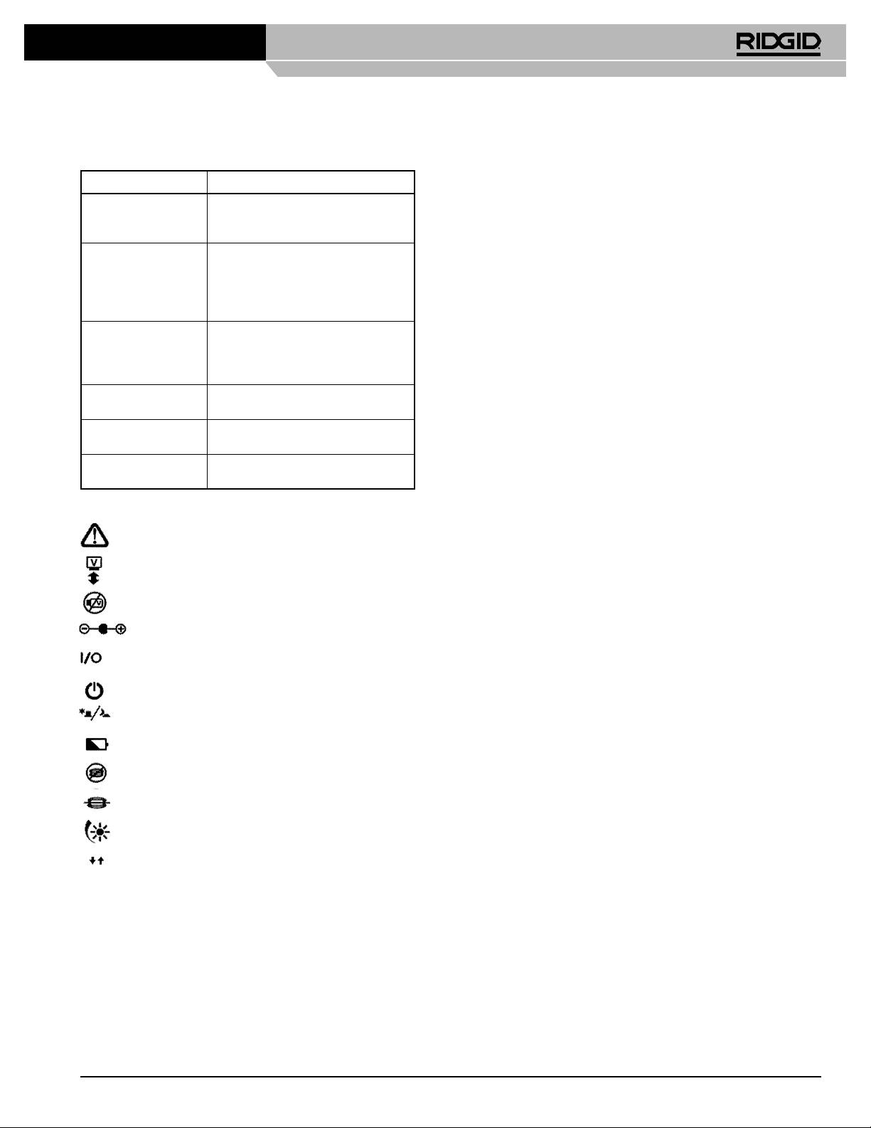
Icon Legend
Caution Symbol
Video In/Out Connector
No Video Signal
External Power Jack (14-16 VDC)
Power On/Off
Power On Led
Day/Night Switch
Battery Status
Transmitter De-activated
Transmitter Activated (LED)
Dimmer Status
Monitor Image Invert
Ridge Tool Company
5
