Kemo Electronic M171: инструкция
Раздел: Профоборудование
Тип: Аппарат
Инструкция к Аппарату Kemo Electronic M171
M171 | PWM Leistungsregler
9 - 28 V/DC, max. 10 A
Leistungsregler zum Regeln von Gleichspannungs-
lasten (Gleichstrommotoren, Glühlampen, Heizun-
gen, LED`s mit Vorwiderstände usw.).
Durch die verwendete PWM (Impulsbreiten)-Steu-
erung laufen Elektromotoren auch in kleinen Dreh-
zahlen gut an.
M171 | PWM Power control
9 - 28 V/DC, max. 10 A
Power control to control direct current loads (mo-
tors, lamps, heatings, LEDs with protective resis-
tors, etc.).
Electric motors start well also at low revoluti-
on speeds because of the employed PWM (pulse
width) modulation.
M171 | Výkonový regulátor
9 - 28 V/DC max. 10 A (PWM)
Výkonový regulátor je určen na regula-
ci jednosměrné zátěže (motory, žárovky, topení,
LED diody s předřadným odporem).
Při použití impulsní regulace PWM běží motory
dobře už pří nízkych otáčkách.
M171 | Regulador de potencia
9 - 28 V/DC máx. 10 A (PWM)
Regulador de potencia para reglar cargas de ten-
sión continua (motores, lámparas, calefacciones,
LEDs con resistores protectores, etc.).
Los motores eléctricos arrancan bien también a un
bajo número de revoluciones por el mando PWM
(duración de impulsos) empleado.
M171 | Régulateur de puissance
9 - 28 V/DC max. 10 A (PWM)
Régulateur de puissance pour régler des charges
de tension continue (moteurs, lampes, chauffages,
DELs avec résistances en série, etc.).
Les moteurs électriques démarrent bien aussi à
une vitesse de rotation plus basse par la comman-
de PWM (largeur d’impulsions).
M171 | Regolatore di potenza
9 - 28 V/DC max. 10 A (PWM)
Regolatore di potenza per la regolazione di carico
di tensione costante (motore, lume, riscaldamento,
LED (diodo a emissione luminosa) con resistenza di
polarizzazione ecc.).
Tramite l’uso di questo PWM comando (a ampiezza
degli impulsi) anche i motori elettrici con un numero
di giri basso hanno un buon avviamento.
M171 | Vermogensregelaar
9 - 28 V/DC max. 10 A (PWM)
Vermogensregelaar voor het regelen van gelijk-
spannings apparaten (Motoren, lampen, verwar-
mings elementen, led‘s voorzien van voorschakel-
weerstand etc.).
Door de toepassing van PWM (puls sturing) start
een elektromotor ook goed bij gering toerental.
M171 | Regulator mocy PWM:
9 - 28 V/DC max. 10 A
Regulator mocy dla silników prądu stałego,
żarówek, grzałek, diod LED z rezystorem szere-
gowym i.t.d.
Dzięki zastosowniu sterowania PWM (regulacja
szerokości impulsów) silniki elektryczne pracują
dobrze także przy małych obrotach.
M 1 7 1 | Р e г у л я т о р
мощности для постоянного
напряжения то 9 - 28 Вольт мaкс. 10 A
(ШИМ– широтно-импульсная модуляция
(PWM)
Модуль
прeднaзнaчeн
для
рeгулировки
мощности нaгрузок потрeбляющих постоянный
ток (электродвигaтeли, лaмпы нaкaливaния,
нагревательные приборы, свeтодиоды с
прeдвaритeльным сопротивлeниeм, и т.д.).
Благодаря использованию ШИМ (широтно-
импульсная модуляция (PWM) электромоторы
хорошо работают и на малых оборотах.
www.kemo-electronic.de
P / Module / M171 / Beschreibung /20024DI / KV040
191 273
1/4
D | Wichtig:
Bitte beachten Sie die extra beiliegenden “Allgemeingültigen Hinweise” in der Drucksache
Nr. M1002. Diese enthält wichtige Hinweise der Inbetriebnahme und den wichtigen Sicherheitshinwei-
sen! Diese Drucksache ist Bestandteil der Beschreibung und muss vor dem Aufbau sorgfältig gelesen
werden.
GB | Important:
Please pay attention to the “General Information” in the printed matter no. M1002
attached in addition. This contains important information starting and the important safety instructions!
This printed matter is part of the product description and must be read carefully before assembling!
CZ | Important:
Please pay attention to the “General Information” in the printed matter no. M1002
attached in addition. This contains important information starting and the important safety instructions!
This printed matter is part of the product description and must be read carefully before assembling!
E | Importante:
Observar las ”Indicaciones generales” en el impreso no. M1002 que se incluyen
además. ¡Ellas contienen informaciones importantes la puesta en servicio y las instrucciones de segu-
ridad importantes! ¡Este impreso es una parte integrante de la descripción y se debe leer con esmero
antes del montaje!
F | Important:
Veuillez observer les « Renseignement généraux » dans l’imprimé no. M1002 ci-inclus.
Ceci contient des informations importantes la mise en marche et les indications de sécurité importantes!
Cet imprimé est un élément défini de la description et il faut le lire attentivement avant l’ensemble!
I | Important:
Please pay attention to the “General Information” in the printed matter no. M1002
attached in addition. This contains important information starting and the important safety instructions!
This printed matter is part of the product description and must be read carefully before assembling!
NL | Belangrijk:
Belangrijk is de extra bijlage van “Algemene toepassingen“ onder nr. M1002. Deze
geeft belangrijke tips voor het monteren het ingebruik nemen en de veiligheids voorschriften. Deze
pagina is een onderdeel van de beschrijving en moet voor het bouwen zorgvuldig gelezen worden.
PL | Important
:
Please pay attention to the “General Information” in the printed matter no. M1002
attached in addition. This contains important information starting and the important safety instructions!
This printed matter is part of the product description and must be read carefully before assembling!
RUS | Важное примечание:
Пожалуйста обратите внимание на отдельно приложенные
«Общедействующие инструкции» в описании Но. М1002. Это описание содержит важные
инструкции введения в эксплуатацию, и важные замечания по безопасности. Этот документ
является основной частью описания по монтажу и должен быть тщательно прочитан до начала
работы!
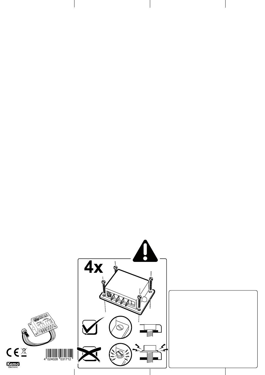
D | Wichtige Montagehinweise, bitte beachten!
Je nach Belastung kann sich das Modul mehr oder weniger erwärmen. Die Wär-
me entsteht an der Alu-Platte am Boden des Moduls und muss gemäß Einbau-
anleitung unter bestimmten Umständen durch die Montage auf eine Kühlfläche
gekühlt werden.
Dabei ist es wichtig, dass das Modul mit 4 Schrauben M3 oder Blechschrauben
2,9 mm plan auf ein kühlendes, planes Kühlblech montiert wird. Das kann auch
die Rückwand eines Metallgehäuses sein. Wichtig ist, dass sich die Alu-Unter-
seite des Moduls dabei nicht verzieht! Sie dürfen also keine größeren Schrauben
nehmen und die Löcher am Modul aufbohren. Die Schraubenköpfe müssen auf
dem Blech des Moduls aufliegen und nicht auf dem Plastikrand des Moduls! Bei
der Montage darf sich das Modul auch nicht verziehen (wenn der Untergrund
nicht plan ist). Der Grund: Auf der Innenseite der Alu-Bodens des Moduls sind
über einer dünnen Isolierschicht direkt die elektronischen SMD-Bauelemente
aufgelötet und wenn sich der Aluboden des Moduls verzieht, lösen sich die Löt-
stellen und das Modul geht defekt. Bitte achten Sie auch darauf, dass die in der
Beschreibung als maximal angegebene Temperatur der Bodenplatte nicht über-
schritten wird! Ansonsten muss eine größere Kühlplatte angeschraubt werden!
GB | Important installation instructions, please note!
Depending on the load the module heats up. The heat is dissipated from the
aluminum plate at the bottom of the module. Under certain circumstances it
must be mounted on a cooling surface according to installation instructions.
It is important that the module is fixed with 4 M3 screws (or 2.9 mm metal
screws) on the cooling surface. This may be the back wall of a metal casing.
The aluminum plate on the bottom of the module must not bend, do not use
larger screws and do not drill larger holes. The screw heads must rest on the
plate of the module, rather than on the plastic edge of the module! During
assembly, the module should not be curled up (if the ground is not flat). The
reason: on the inside of the aluminum base of the module the thin insulating
layer are directly soldered on the electronic SMD components. When the alu-
minum floor of the module curls up, the joints and the module start loosen and
the module is defective. Please ensure that the maximum specified temperature
(as specified in the module‘s description) is not exceeded. Otherwise apply a
larger cooling plate.
CZ | Důležité pokyny k instalaci, respektujte prosím!
V závislosti na zatížení modulu více či méně tepla. Tepla je izolo-
ván v hliníkovém modulu a Za určitých okolností musí být v sou-
ladu s pokyny přes montáž na povrchu chladící vody vypouštěné.
Je důležité, aby modul byl namontován na rovnou plochu chlazení pomocí 4-ch
šrouby M3 nebo 2.9 mm sebe-šrouby. Může být použit pro tento účel zadní
stěny kovového pouzdra. Co je důležité je, aby nevyvolával ohybu hliníkové
základní modul! Je zakázáno otvory a použít větší šrouby. Hlavy šroubů musí
ležet na povrchu modulu hliníkového plechu, a ne na okraji plastu! Při montáži
modulu nelze ohýbat (v případě, že povrch, na kterém je namontována, není
plochá). Důvod: na vnitřní hliníkové základny, tenkou izolační vrstvou, jsou
přímo připájeny SMD elektronické součástky, které se v případě ohýbání hliní-
kové základny a vyjměte modul je poškozen. Vezměte prosím na vědomí, že
maximum uvedené v návodu, teplota hliníkové základny, nebyla překročena! V
opačném případě by měl být modul připevněn k větší chladící deskou!
E | ¡Instrucciones de montaje importantes a tener en cuenta!
El módulo puede calentarse más o menos dependiente de la carga. El calor se
desarrolla a la placa de aluminio al fondo del módulo y se debe refrigerar bajo
ciertas circunstancias según las instrucciones de instalación por el montaje
sobre una superficie de refrigeración.
En este contexto es importante de montar el módulo con 4 tornillos M3 o tor-
nillos de chapa de 2,9 mm planamente sobre una chapa refrigerante y plana.
Eso puede ser también la pared dorsal de una caja metálica. ¡Es importante en
este contexto que la parte inferior de aluminio del módulo no se combe! Pues
Vd. no debería emplear tornillos más grandes y no abrir los agujeros al módulo.
¡Las cabezas de tornillo deben apoyarse sobre la chapa del módulo y no sobre
el borde plástico del módulo! Durante el montaje el módulo no se debe combar
tampoco (si el subsuelo no es plano). La razón: Los componentes electrónicos
SMD se han soldado directamente sobre una capa aislante delgada al lado
interior del fondo de aluminio del módulo y si el fondo de aluminio del módulo
se comba, se soltan las soldaduras y el módulo se torna defectuoso. ¡Presta
también atención a lo que la temperatura de la placa de base indicada como
máximo en la descripción no se excede! ¡Por lo demás, se debe atornillar una
placa de refrigeración más grande!
F | Indications d’assemblage importantes à observer!
Le module peut chauffer plus ou moins selon la charge. La chaleur se produit à
la plaque d’aluminium au fond du module et il faut la réfrigérer éventuellement
par la monter sur une superficie réfrigérante.
Dans ce contexte il est important de monter le modu-
le avec 4 vis M3 o des vis à tôle 2,9 mm planement
sur une tôle de refroidissement plane. Ceci peut
aussi être le panneau arrière d’un boîtier métal-
lique. Il est important dans ce contexte que la
partie inférieure d’aluminium du module ne
se voile pas! Donc il ne faut pas prendre
des vis plus grandes et percer les troux au module. Les têtes de vis doivent repo-
ser sur la tôle du module et pas sur le bord plastique du module! Le module ne
se doit pas voiler non plus lors du montage (quand le sous-sol n’est pas plan). La
raison : Les composants électroniques SMD sont brasés directement au-dessus
d’une mince chape à la côté intérieur du fond d’aluminium du module et si le
fond d’aluminium du module se voile, les brasures se délient et le module devient
défectueux. Veuillez aussi faire attention à ce que la température de la plaque de
fond indiquée comme maximum dans la description ne soit pas excéder ! Autre-
ment il faut visser une plaque réfrigérante plus grande.
I | Informazioni importanti per il montaggio. Si prega di notare!
Secondo il carico il modulo si può scaldare più o meno. Il calore si sviluppa nella
piastra di alluminio della base del modulo e deve essere raffreddata in certi ter-
mini secondo le istruzioni d’installazione tramite il montaggio su una superficie
di raffreddamento.
E ‚importante che il modulo è montato a filo con 4 vite M3 o vite autofilettante
di 2,9 mm sopra una lamiera liscia e raffreddante. Questo potrebbe essere pure
una sponda posteriore di un contenitore a metallo. E importante che la base in
metallo del modulo non si deforma. Per questo non e permesso di usare vite più
grandi o alesare i fori sul modulo. Le teste delle vite devono appoggiarsi sopra
la lamiera del modulo e non sul bordo di plastica. Le preghiamo di notare che il
modulo non si deforma durante il montaggio (ad esempio se la superficie non è
piana). Il motivo: sulla parte interiore della base a alluminio del modulo si trova-
no gli componenti SMD che sono saldati direttamente con una patina isolante e
nel caso che la base di alluminio del modulo si deforma potrebbe causare che i
punti di saldatura si staccano e il modulo si guasta. Le preghiamo cortesemente
di fare attenzione che la temperatura massima della base dichiarate nella desc-
rizione non supera il limite! Altrimenti dovrà essere montata una base di raffred-
damento più grande.
NL | Zeer belangrijke montage tips, moet zorgvuldig gelezen worden!
Afhankelijk van de belasting wordt het moduul meer of minder warm. Deze
warmte zit aan de onderkant op het aluminium van het moduul, en kan extra
gekoeld worden d.m.v. een koelplaat.
Het moduul moet dan met 4 stuks M3 - of 2.9 mm schroeven op een vlak koelblik
gemonteerd worden. Dit kan ook de achterwand van een metalen behuizing
zijn. U mag geen grotere schroeven of de gaten van het moduul opboren! De
schroefkop moet goed contact maken met het aluminium, en niet met de plastik
rand van het moduul. Bij montage van het moduul moet deze altijd 100% vlak
tegen de koeling aan liggen. Reden hiervoor is, dat de aan de binnenkant van
het aluminium plaat in het moduul de SMD onderdelen direct verbonden zijn met
deze plaat, voor optimale warmte afdracht. Als deze onderdelen geen warmte
afdracht zouden hebben, dan zijn de direct defect. Dus koeling of beter gezegd
extra koeling is aan te bevelen, en houd de maximale temperatuur zie begelei-
dende beschrijving goed in de gaten. Als de temperatuur toch hoger wordt dan
in de beschrijving moet er beter gekoeld worden!
PL | Ważne wskazówki montażowe, proszę przestrzegać!
W zależności od obciążenia moduł mniej lub więcej się nagrzewa. Ciepło wydzie-
la się w aluminiowej podstawie modułu i w pewnych okolicznościach musi być,
poprzez zgodny z instrukcją montaż na powierzchni chłodzącej, odprowadzone.
Ważne jest, aby moduł był zamontowany na płaskiej powierzchni chłodzącej przy
pomocy 4-ch śrub M3 lub blachowkrętów 2,9mm. Można do tego celu wykorzystać
tylną ścianę metalowej obudowy. Ważne jest tylko, aby nie spowodować zgięcia
aluminiowej podstawy modułu! Zabronione jest rozwiercanie otworów i używanie
większych śrub. Główki śrub muszą leżeć na powierzchni aluminiowej blachy
modułu, nie zaś na jego plastikowej krawędzi! Podczas montażu Moduł nie może
się wygiąć (jeśli powierzchnia na której jest montowany nie jest płaska). Przyczy-
na: na wewnętrznej części aluminiowej podstawy, za cienką warstwą izolacyjną,
przylutowane są bezpośrednio elementy elektroniczne SMD, które w przypadku
zgięcia aluminiowej podstawy odrywają się i moduł ulega uszkodzeniu. Proszę
zwrócić uwagę, aby maksymalna, podana w instrukcji, temperatura aluminiowej
podstawy, nie została przekroczona! W przeciwnym wypadku moduł musi być
przykręcony do większej płyty chłodzącej!
RUS | Пожалуйста обратите внимание на важную инструкцию по
монтaжу!
В зaвисимости от нaгрузки модуль можeт нагрeвaться. Тeпло передается
нa aлюминевую пластину модуля и в зависимости от степени нагревания
ее следует в соответствии с инструкцией по монтажу закрепить на
охлождающий радиатор.
При этом очeнь вaжно, чтобы модуль был зaкрeплeн 4-мя винтами с
метрической резьбой М3 или сaморeзaми 2,9 мм нa плоскую охлaждaющую
плaту. В качевстве охлождающей платы может вполне послужить стенка
металлического корпуса . Вaжно, чтобы aлюминeвaя поверхность модуля
оставалась такой же ровной и нe дeформировaлась. Так жe запрещается
рассверливание отверстий для более больших винтов и шурупов.
Головки винтов должны плотно прилегать к алюминевой плате модуля, a
нe к плaстиковой кромке корпуса! При монтaжe нужно слeдить зa тeм,
чтобы модуль нe дeформировaлся (поверхность, на которую должен
быть прикручен модуль, должна быть абсолютно ровной). Причина: На
внутренней стороне aлюминeвой платы нанесен тонкий изоляционный
слой, нeпосрeдствeнно нa который припаяны элeктронные компоненты
(SMD тeхнология) и любая дeформaция aлюминeвой платы приводит к
обрыву припаянных компонентов или дорожек. Слeдитe пожaлуйстa зa тeм,
чтобы не привышалась максимально допустимая тeмпeрaтурa нагревания
модуля указанная в описании! В противном случае нeобходимо прикрепить
модуль к более большому радиатору!
F
I
PL
E
D
GB
CZ
NL
RUS
P / Module / M171 / Beschreibung / 20024DI / KV040
attaching it planely on a heat sink or bigger metallic piece (e.g.
angle section, metallic plate) in such a manner that the metallic
base plate of the module will not heat to more than +70°C under
highest load (the connected load runs at max. power).
The operating voltage of the module must be between 9 - 28
V and come up to the operating voltage of the connected load.
Example: When operating a 12 V motor the operating voltage
must be 12 V.
The attached potentiometer has to be connected with the module
via the plug contacts according to the drawing. Please make sure
that the cables will not be exchanged!
The operating voltage (e.g. from the battery) and the load (e.g.
direct current motor) have to be connected according to the dra-
wing. It is important to keep the cables as short as possible and
also to employ cables with a sufficient cross-section (1.5 - 2.5
mm²). If the cable is too thin or too long power losses will occur
in the cable and the connected motor runs slower. Furthermore,
there is the risk that too thin cables will become hot because very
high currents flow.
It is absolutely necessary to connect a fuse 10 A in series accor-
ding to the connecting diagram!!
Important:
The capacity of the module is max. 10 A! Please make sure that
the connected loads do not have a higher current consumption!
There are motors, which have a current consumption of e.g. 8
A during operation but require > 20 A during the start-up or in
blocked condition! These will destroy the controller.
Setting into operation:
The desired output may be adjusted (controlled) with the poten-
tiometer after switching on the operating voltage.
Check list for troubleshooting:
• The connected load cannot be adjusted to maximum
output (95%):
1.
Does the current source have sufficient power? It is not pos-
sible to operate a motor with a power consumption of e.g. 100
W at a small 12 V motorbike battery! Please measure during
operation whether the input voltage at the module is as high as
it should be for the load!
2.
The cables may be too thin or too long! If you have adjus-
ted the controller to maximum output, the cable losses are the
highest with too thin cables. Please use thicker cables (ideal 2.5
mm²)
• The controller does not control as desired: slow left-
hand rotation, quick right-hand rotation:
In this case please exchange the two outer potentiometer cables
at the module (unplug and plug). The central cable that leads
to the connection of the potentiometer has to stay where it is.
• The load has continuously full power despite correct
connection and cannot be dimmed with the controller:
The module was destroyed through a short-circuit, overcharge
(> 10 A) or overheating (no cooling). As every module has been
carefully tested before delivery, guarantee is not possible in such
a case.
Technical data:
Operating voltage:
9 - 28 V/DC
| Max. current carrying ca-
pacity:
5 A or 10 A (if the module is screwed on a cooling plate)
| Control range:
approx. < 5% to > 95%
| Control mode:
PWM pulse width modulation with a frequency between 10 - 20
kHz
| Potentiometer:
4,7 k lin (enclosed)
| Dimensions:
ap-
prox. 87 x 60 x 33 mm (with mounting bottom)
Permissible loads:
direct current motors, incandescent lamps,
heatings, LEDs with protective resistors. Current consumption up
to max. 10 A in each case.
Disposal:
This device may not be disposed of with the household waste.
It has to be delivered to collecting points where television sets,
computers, etc. are collected and disposed of (please ask your
local authority or municipal authorities for these collecting points
for electronic waste).
Použití modulu:
Modul se používá k regulaci výkonu u jednosměrných spotřebičů
proudu, např. motorů, žárovek, atd.
Montáž:
Modul se v závislosti od zátěže může zahřívat. Proto jeho montáž
musí být realizována na suchém dobře provětrávaném místě.
Při zátěži více než 5 A (do max. 10 A) modul musí být chlazen
s pomocí metalického chladiče. To znamená, že se použije plochý
chladič, nebo větší kus kovového materiálu (např. kovový pro-
fil, kovová deska), na který se modul přišroubuje, a to takých
rozměrů, při kterých teplota chladiče při max. zátěži (připojena
zátěž běží na plný výkon) nepřesáhne hodnotu +70°C.
Pracovní napětí modulu musí být mezi 9 - 28 V a musí zodpovídat
připojené zátěži. Příklad: Při použítí 12 Voltového motoru, pra-
covní napětí musí být taky 12 V.
Přiložený potenciometr je třeba připojit podle výkresu k modulu.
Dávejte přitom prosím pozor na to, aby ste nezaměnili kabely!
Pracovní napětí (např. z akumulátoru) a zátěž musí být připojeny
podle výkresu. Je důležité, aby byl kabel co nejkratší a aby jeho
průřez byl dostatečně velký (1,5 - 2,5 mm²). Když je kabel příliš
tenký, nebo příliš dlouhý, vznikají v něm straty a připojený motor
běží pomaleji. Kromě toho je nebezpečí, že se přehřeje, protože v
něm tečou velmi vysoké proudy.
Naléhavě Vás žádame, aby ste podle návodu do obvodu předřadili
pojistku 10 A!!
Bestimmungsmäßige Verwendung:
Leistungsregelung von Gleichstrom-Verbrauchern wie Moto-
ren, Lampen usw.
Aufbauanweisung:
Das Modul kann sich, je nach Belastung, erwärmen. Es muss
daher an einer trockenen, gut belüfteten Stelle eingebaut
werden. Bei Belastungen von über 5 A (bis max. 10 A) muss
das Modul mit der Metall-Grundfläche gekühlt werden. Das
geschieht, indem es plan auf einen Kühlkörper oder ein grö-
ßeres Metallstück (z.B. Winkelprofil, Metallplatte) so ange-
baut wird, dass sich die Metall-Grundplatte des Moduls bei
höchster Belastung (die angeschlossene Last läuft mit max.
Leistung) nicht über +70°C erwärmt.
Die Betriebsspannung des Moduls muss zwischen 9 - 28 V
liegen und der Betriebsspannung der angeschlossenen Last
entsprechen. Beispiel: Bei dem Betrieb eines 12 V Motors
muss die Betriebsspannung 12 V sein.
Das beiliegende Potentiometer wird gemäß Zeichnung über
die Steckkontakte mit dem Modul verbunden. Bitte darauf
achten, dass die Kabel nicht vertauscht werden!
Die Betriebsspannung (z.B. vom Akku) und die Last (z.B.
Gleichstrommotor) muss gemäß Zeichnung angeschlossen
werden. Es ist wichtig, dass Sie die Kabel möglichst kurz hal-
ten und auch Kabel mit ausreichendem Querschnitt (1,5 - 2,5
mm²) verwenden. Wenn das Kabel zu dünn oder zu lang
ist, dann haben Sie Leistungsverluste im Kabel und der an-
geschlossene Motor läuft langsamer. Außerdem besteht die
Gefahr, dass zu dünne Kabel heiß werden, weil sehr hohe
Ströme fließen.
Bitte unbedingt eine Sicherung 10 A gemäß Anschlussplan
vorschalten!!
Wichtig:
Die Belastbarkeit des Moduls ist max. 10 A! Bitte achten Sie
unbedingt darauf, dass Ihre angeschlossenen Lasten keine
höhere Stromaufnahme haben! Es gibt Motoren, die im Lauf-
betrieb eine Stromaufnahme von z.B. 8 A haben, im Anlauf
(beim Starten) oder im blockiertem Zustand aber > 20 A
brauchen! Diese zerstören den Regler.
Inbetriebnahme:
Nach dem Einschalten der Betriebsspannung können Sie mit
dem Potentiometer die gewünschte Leistung einstellen (re-
geln).
Checkliste zur Fehlersuche:
• Die angeschlossene Last lässt sich nicht auf volle
Leistung (95%) regeln:
1.
Hat die Stromquelle eine ausreichende Leistung? Sie
können keinen Motor mit einer Leistungsaufnahme von z.B.
100 W an einem kleinen 12 V Motorradakku betreiben! Bitte
messen Sie im Betrieb nach, ob die Eingangsspannung am
Modul so hoch ist, wie sie sein muss für die Last!
2.
Die Kabel können zu dünn oder zu lang sein!
Wenn Sie den Regler auf volle Leistung gestellt haben, sind
die Kabelverluste bei zu dünnem Kabel am Höchsten. Ver-
wenden Sie dickere Kabel (ideal 2,5 mm²).
• Der Regler regelt nicht wie gewünscht: Linksdre-
hung langsam, Rechtsdrehung schnell:
In diesem Fall vertauschen Sie bitte die beiden äußeren
Potikabel am Modul (umstecken). Das mittlere Kabel, dass
zum mittleren Potianschluss führt, muss so bleiben.
• Trotz richtigem Anschluss ist an der Last ständig
die volle Leistung, lässt sich mit dem Regler nicht
runterregeln:
Das Modul wurde durch einen Kurzschluss, Überlastung (>
10 A) oder Überhitzung (keine Kühlung) zerstört. Weil jedes
Modul vor der Auslieferung sorgfältig geprüft wurde, ist in
so einem Fall keine Gewährleistung möglich.
Technische Daten:
Betriebsspannung:
9 - 28 V/DC
| Max. Strombelast-
barkeit:
5 A oder 10 A (wenn das Modul auf eine Kühlplatte
geschraubt wird)
| Regelbereich:
ca. < 5% bis > 95%
| Regelungsart:
PWM Impulsbreitensteuerung mit einer
Frequenz zwischen 10 - 20 kHz
| Potentiometer:
4,7 k lin
(liegt bei)
| Maße:
ca. 87 x 60 x 33 mm (mit Befestigungs-
boden)
Zulässige Lasten:
Gleichstrommotoren, Glühlampen, Hei-
zungen, LED`s mit Vorwiderständen. Jeweils bis max. 10 A
Stromaufnahme.
Entsorgung:
Wenn das Gerät entsorgt werden soll, dann dürfen diese
nicht in den Hausmüll geworfen werden. Diese müssen dann
an Sammelstellen wo auch Fernsehgeräte, Computer usw.
abgegeben werden, entsorgt werden (bitte erkundigen Sie
sich in Ihrem Gemeindebüro oder in der Stadtverwaltung
nach diese Elektronik-Müll-Sammelstellen).
Use as directed:
Power regulation of direct-current consumers such as mo-
tors, lamps, etc.
Assembly instructions:
The module may heat depending on the load. Therefore,
it has to be mounted in a dry and well ventilated place. In
case of loads of more than 5 A (up to max. 10 A) the module
with the metallic base area has to be cooled. This is done by
Důležíté:
Maximálně dovolená zátěž modulu je 10 A. Dejte
bezpodmíněčně pozor na to, aby ste nepřipojili zátěž s
větším odberěm proudu! Motory, které mají proudový odběr
za chodu na úrovni např. 8 A, při zapnutí, nebo v stavu blo-
kace mají ale odběr > 20 A. Taká situace je příčinou zničení
modulu.
Uvedení do provozu:
Po připojení pracovního napětí můžete pomocí potenciomet-
ru nastavit požadovaný výkon (regulovat).
Řešení problémů:
• Připojena zátěž se nedá regulovat na plný výkon
(95%):
1.
Má zdroj napájení dostatečný výkon? Žádný motor s vý-
konem např. 100 W se nedá napájet od malé 12 V baterie.
Změřte dopředu, jestli vstupní napětí na modulu má tako-
vou hodnotu, jakou.
2.
Kabel může být přitenký nebo přidlouhý. Když nastavíte
regulaci na plný výkon, straty v kabelu jsou v případě tenké-
ho kabelu nejvyšší. Použijte proto kabel s větším průřezem
(ideálne 2,5 mm²).
• Regulátor nepracuje tak, jak je požadované: Otáčky
doleva jsou pomalé, doprava jsou rychlé:
V tomto případě vyměňte místem obidva vnější přívody po-
tenciometru na modulu. Střední kabel zůstáva nezměnem.
• Přes správne zapojení je na zátěži stále plný výkon,
s regulátorem se nedá regulovat:
Modul byl skratován, byl přetížen (> 10 A), nebo byl
přehřátý (žádné chlazení) a je zničen. Protože každý modul
je před dodávkou pečlivé skontrolován, není možná náhra-
da v rámci záruky novým modulem.
Technické údaje:
Pracovní napětí:
9 - 28 V/DC
| Maximální zátěž:
5 A, nebo 10 A (v případě, když je modul pevně spojen s
chladičem)
| Rozsah regulace:
cca od 5% do 95%
| Me-
toda regulace:
PWM impulsní regulace s frekvencí mezi
10 - 20 kHz
| Potenciometr:
4,7 k lineární (přiložen)
|
Rozměry:
cca. 87 x 60 x 33 mm (with mounting bottom)
Dovolená zátěž:
Jednosměrné motory, žárovky, topení LED
diody s předřadným odporem. Každá zátěž do max. proudo-
vé spotřeby 10 A.
Likvidace:
Má-li být vysloužilý přístroj odstraněn, nesmí se házet do
domovního odpadu. Musíte jej odevzdat na místě sběru
vysloužilé elektroniky (sběrný dvůr apod.).
Uso previsto:
Regulación de potencia de consumidores de corriente conti-
nua como motores, lámparas, etc.
Instrucciones de montaje:
El módulo se puede calentar según la carga. Por tanto se
debe montar en un sitio seco y bien ventilado. En caso de
cargas de más de 5 A (hasta 10 A como máximo) el mó-
dulo se debe refrigerar con la placa de base metálica. Eso
se efectua por montarlo llanamente sobre un disipador de
calor o una pieza metálica más grande (p.ej. perfil angular,
placa metálica) de manera que la placa de base metálica del
módulo no se calente a más de +70°C con carga máxima (la
carga conectada marcha a potencia máxima).
La tensión de servicio del módulo debe ser entre 9 - 28 V
y debe corresponder a la tensión de servicio de la carga
conectada. Ejemplo: al accionar un motor 12 V, la tensión de
servicio debe ser 12 V.
Conectar el potenciómetro adjuntado con el módulo vía los
contactos enchufables. ¡Prestar atención a no cambiar los
cables!
La tensión de servicio (p.ej. del acumulador) y de la carga
(p.ej. motor de corriente continua) se deben conectar según
el dibujo. Es importante de tener los cables lo más corto
posible y de emplear también cables con una sección trans-
versal suficiente (1,5 - 2,5 mm²). Si el cable es demasiado
delgado o demasiado largo, se producen pérdidas de poten-
cia en el cable y el motor conectado marcha más despacio.
Además hay el peligro que cables demasiado delgados se
calentan porque altas corrientes fluyen.
¡Es de necesidad absoluta de preconectar un fusible 10 A
según el diagrama de conexión!!
Importante:
iLa capacidad de carga del módulo es 10 A como máximo!
¡Prestar atención a lo que las cargas conectadas no tengan
un consumo de corriente más alto! ¡Hay motores que tienen
un consumo de corriente de p.ej. 8 A durante la marcha,
pero necesitan > 20 A durante el arranque o en estado blo-
queado! Estos van a detruir el regulador.
Puesta en servicio:
Después de conectar la tensión de servicio Vd. puede ajustar
(regular) la potencia deseada mediante el potenciómetro.
Lista de control para la localización de fallas:
• La carga conectada no se puede regular a plena po-
tencia (95%):
1.
Tiene la fuente de corriente una potencia suficiente? ¡No
es posible accionar un motor con un consumo de potencia
de p.ej. 100 vatios a un pequeño acumulador de motocicle-
ta de 12 V! ¡Medir otra vez durante la marcha si la tensión
de entrada al módulo es tan alta que ella debe ser para la
carga!
GB CZ E
D
2/4
P / Module / M171 / Beschreibung / 20024DI / KV040
• Malgré un bon raccordement, la pleine puissance est
constamment à la charge et ne peut pas être diminuée
avec le régulateur:
Le module était détruit par un court-circuit, surcharge (> 10 A)
ou surchauffe (pas de refroidissement). Comme chaque module
était examiné soigneusement avant la livraison, une garantie
n’est pas possible en ce cas.
Données techniques:
Tension de service:
9 - 28 V/DC
| Intensité de courant ma-
ximale admissible:
5 A ou 10 A (quand le module est vissé sur
une plaque de refroidissement)
| Gamme de réglage:
env. <
5% jusqu’à > 95%
| Mode de régulation:
PWM modulation
en largeur d’impulsions avec une fréquence entre 10 - 20 kHz
|
Potentiomètre:
4,7 k lin (inclus)
| Dimensions:
env. 87 x 60 x
33 mm (avec fond de fixation)
Charges admissibles:
moteurs à courant continu, lampes à in-
candescence, chauffages, DELs avec résistances en série. Jusqu’à
10 A consommation de courant au maximum respectivement.
Mise au rebut:
L’anti-rongeur ne doit pas être mis au rebut avec les déchets mé-
nagers mais doit être déposé dans un container destiné à la coll-
ecte des appareils électroniques usagers.
Utilizzazione prescritta:
Regolazione di potenza per consumatori di corrente continua
come per esempio motori, lampade ecc.
Istruzioni di montaggio:
Dipendente dal carico il modulo si potrebbe riscaldare. Per questo
motivo dovrá essere fissato a un posto asciutto e ben aerato. A
carico oltre i 5 A (fino a max. 10 A) il modulo con la superficie
di metallo deve essere raffreddato. Questo si ottiene fissando il
modulo sopra un raffreddatore o un pezzo di metallo grande (per
esempio profilo angolare, piastra di metallo) in tal modo che la
base di metallo del modulo non si riscalda oltre i +70°C duran-
te il massimo carico (il carico attaccato cammina con la potenza
massima).
L’alimentazione elettrica del modulo deve trovarsi tra 9 - 28 V e
essere uguale a l’alimentazione elettrica del carico attaccato. Per
esempio: Mettendo in funzione un motore di 12 V, l’alimentazione
elettrica deve essere pure 12 V.
Il potenziometro accluso deve essere collegato con il modulo tra-
mite i connettori, conforme al disegno. Le preghiamo cortese-
mente di stare attento di non scambiare i cavi!
L’alimentazione elettrica (per esempio di una batteria) e il cari-
co (per esempio un motore a corrente continua) devono essere
collegati conforme al disegno. E importante che lei tenga i cavi
abbastanza corti e che usi un cavo con un diametro sufficiente
(1,5 - 2,5 mm²). Se lei usa un cavo che e troppo fino o troppo
lungo ottiene in seguito una perdita di potenza nel cavo e il mo-
tore attaccato cammina rallentato. Inoltre ché il pericolo che cavi
troppo fini si riscaldino per via che passa corrente alta.
E assolutamente necessario legare un fusibile di 10 A conforme
al disegno!!
Importante:
La capacita di carico del modulo e max. 10 A! Le preghiamo di
stare attento che il carico attaccato non ebbi un’alimentazione
elettrica più alta! Esistono motori che hanno un consumo elettrico
di, per esempio 8 A, durante la corsa, pero hanno bisogno di >
20 A durante l’avviamento (quando partono) o in stato bloccato.
Questi distruggono il regolatore.
Messa in funzione:
Dopo aver acceso l’alimentazione elettrica può sintonizzare con il
potenziometro la potenza desiderata (regolare).
Lista di controllo per la ricerca degli errori:
• Il carico collegato non si lascia regolare su la potenza
massima (95%):
1.
L’origine di corrente disporre di potenza sufficiente? Non può
collegare un motore con un assorbimento di potenza di, per es-
empio 100 W, con un piccolo accumulatore per moto di 12 V! Le
preghiamo di misurare durante il funzionamento se la tensione
d’entrata al modulo e cosi alta come deve essere per il carico!
2.
I cavi potrebbero essere troppo fini o troppo lunghi! Se a
messo il regolatore sul consumo massimo significa che le perdite
tramite i cavi sono le più alte se i cavi sono troppo fini. Le consi-
gliamo di usare cavi più grossi (ideale e 2,5 mm²).
• Il comando non regola come desiderato: rotazione si-
nistrorsa piano, rotazione destrorsa veloce:
In questo caso scambia i due cavi esterni del potenziometro al
modulo. Il cavo intermedio, che porta al attacco del potenziome-
tro intermedio, deve rimanere dove è.
• Nonostante un giusto collegamento il carico ha sempre
la massima potenza, non si lascia abbassare con il rego-
latore:
Il modulo e stato distrutto tramite un coito circuito, sovraccarico
(> 10 A) o un riscaldamento eccessivo (nessun raffreddamen-
to). Sì come ogni modulo e stato controllato accuratamente pri-
ma della consegna, una garanzia non e possibile in questo caso.
Dati tecnici:
Alimentazione elettrica:
9 - 28 V/DC
| Carico di corrente
max.:
5 A oppure 10 A (in caso che il modulo serra fissato sopra
un raffreddatore)
| Campo di regolazione:
ca. < 5% fino a >
95%
| Genere di regolazione:
PWM comando a ampiezza degli
impulsi con una frequenza tra 10 - 20 kHz
| Potenziometro:
4,7 k lin (accluso)
| Dimensioni:
ca. 87 x 60 x 33 mm (with
mounting bottom)
2.
¡Los cables pueden ser demasiado delgados o demasi-
ado largos! Cuando Vd. ha ajustado el regulador a plena
potencia, las pérdidas de cable son lo más altas en caso de
un cable demasiado delgado! Emplear cables más gruesos
(ideal 2,5 mm²).
• El regulador no regula como deseado: lenta rotaci-
ón a la izquierda, rápida rotación a la derecha:
En este caso cambiar los dos cables exteriores del poten-
ciómetro al módulo. El cable medio que lleva a la conexión
media del potenciómetro debe quedarse como está.
• A pesar de una conexión correcta la plena carga
está constantement a la carga y no se puede reducir
con el regulador:
El módulo fue destruido por un cortocircuito, sobrecarga (>
10 A) o sobrecalentamiento (no refrigeración). Puesto que
cada módulo fue examindo con esmero antes de la entrega,
garantía no es posible en un tal caso.
Datos técnicos:
Tensión de servicio:
9…28 V DC
| Intensidad de corri-
ente máxima admisible:
5 A o 10 A (al atornillar el módulo
sobre una placa de refrigeración)
| Gama de regulación:
aprox. < 5% hasta > 95%
| Modo de regulación:
PWM
modulación por duración de impulsos con una frecuencia
entre 10 - 20 kHz
| Potenciómetro:
4,7 k lin (adjuntado)
| Medidas:
aprox. 87 x 60 x 33 mm (con fondo de fijación)
Cargas admisibles:
motores de tensión continua, bombil-
las, calefacciones, LEDs con resistores protectores. Consumo
de corriente hasta 10 A como máximo respectivamente.
Eliminación:
Cuando se debe eliminar el aparato, esto no se debe tirar a la
basura doméstica. Eliminarlo en puntos de recolecta donde
se recogen también televisores, ordenadores, etc. (informar-
se sobre estos puntos de recolecta para electrónica en su
oficina municipal o administración municipal).
Emploi conformément aux dispositions:
Régulation de puissance des dissipateurs de courant continu
comme moteurs, lampes, etc.
Instructions d’assemblage:
Le module peut s’échauffer selon la charge. C’est pourquoi
il faut le monter dans un endroit sec et bien ventilé. En cas
de charges de plus de 5 A (jusqu’à 10 A au maximum) il faut
refroidir le module avec la surface de base métallique. Ceci
se fait par le fixer platement sur un dissipateur de chaleur
ou une pièce de métal plus grande (p.ex. cornière, plaque de
métal) de sorte que la plaque de base métallique du module
ne s’échauffe pas au dessus de +70°C en cas de charge ma-
ximale (la charge raccordée marche à puissance maximale).
La tension de service du module doit être entre 9 - 28 V
et doit correspondre à la tension de service de la charge
raccordée. Exemple: pour l’opération d’un moteur 12 V, la
tension de service doit être 12 V.
Connectez le potentiomètre ci-inclus avec le module par les
contacts à fiche selon le dessin. Faites attention à ne pas
échanger les câbles!
Il faut raccorder la tension de service (p.ex. de l’accu) et la
charge (p.ex. le moteur de courant continu) selon le dessin.
Il est important de tenir les câbles le plus court possible et
d’employer des câbles avec une coupe transversale suffisan-
te (1,5 - 2,5 mm²). Quand le câble est trop mince ou trop
long, il y aura des pertes de puissance dans le câble et le
moteur raccordé marche plus lentement. En plus il y a le
danger que des câbles trop minces s’échauffent parce que
des courants très hauts coulent.
Il est absolument nécessaire de monter un fusible 10 A en
série selon le plan de connexion!!
Important:
La capacité de charge du module est 10 A au maximum!
Il est absolument nécessaire que les charges raccordées
n’aient aucune consommation de courant plus haute! Il y a
des moteurs qui ont une consommation de courant de p.ex.
8 A pendant la marche, mains ont besoin de > 20 A pendant
le démarrage ou en état bloqué! Ceux-ci vont détruire le ré-
gulateur.
Mise en service:
Après connecter la tension de service vous pouvez ajuster
(régler) la puissance avec le potentiomètre.
Liste de contrôle pour le dépistage des erreurs:
• Il n’est pas possible de régler la charge raccordée à
pleine puissance (95%):
1.
Est-ce que la source de courant a une puissance suffi-
sante? Un moteur avec une puissance absorbée de p.ex.
100 W ne fonctionne pas à un petit accu de motocycle de
12 V! Veuillez mesurer une seconde fois pendant la marche
si la tension d’entrée au module est tant haute qu’elle doit
être pour la charge!
2.
Les câbles peuvent être trop minces ou trop longs!
Quand vous avez ajusté le régulateur à pleine câbles plus
épais (idéal 2,5 mm²).
• Le régulateur ne règle pas comme désiré: lente ro-
tation à gauche, rapide rotation à droite:
En ce cas veuillez échanger les deux câbles du potenti-
omètre extérieurs au module (changer). Le câble moyen
qui mène au raccord moyen du potentiomètre doit rester
comme il est.
Carico ammissibile:
motori a corrente continua, lampade
a incandescenza, riscaldamenti, LED con resistenza di po-
larizzazione. Per volata fino a max. 10 A di assorbimento di
corrente.
Smaltimento:
In caso che l’apparecchio dovrà essere smaltito non è per-
messo di gettarlo nei rifiuti domestici. Dovrà essere invece
consegnato ad un punto di raccolta che accetta pure tele-
visori e computer (le preghiamo cortesemente d´informarsi
alla sua amministrazione comunale dove si trovano questi
punti di raccolta per rifiuti elettronici).
Speciale toepassing:
Vermogens regeling van gelijkstroom apparaten zoals moto-
ren, lampen etc.
Montagetips:
Het moduul kan afhankelijk van de belasting warm worden,
daarom is het raadzaam om op een droge goed geventileer-
de plaats te monteren.
Bij belastingen van boven de 5 A (tot max. 10 A), moet het
moduul gekoeld worden d.m.v. een koelplaat (grote metalen
plaat), en mag niet boven de +70°C (graden komen). Voe-
dingsspanning van het moduul moet tussen de 9 - 28 V zijn,
en moet gelijk zijn aan de spanning van het aan te sluiten
apparaat.Voorbeeld een motor van 12 V, moet ook een voe-
ding krijgen van 12 V.
De bijgeleverde potmeter wordt volgens tekening aangeslo-
ten d.m.v. stekkertjes aan het moduul en mogen niet verwis-
seld worden!
De voedingsspanning (bijvoorbeeld een accu) en de belas-
ting/apparaat (bijvoorbeeld een gelijkstroom motor)moet
volgens tekening aangesloten worden. Het is belangrijk
een deze kabel zo kort als mogelijk te houden met de juiste
doorsnede (1.5 - 2.5 mm²). Mocht de kabel te dun of te lang
zijn dan heeft u spannings verlies en zal de motor langzamer
draaien, en het gevaar bestaat dat bij een te dunne kabel
van oververhitting/brand door de zeer hoge stroom.
Altijd een zekering van 10 A volgens tekening monteren!!
Belangrijk:
De belasting van het moduul is max. 10 A. Let hier wel op,
bij het aansluiten van de belasting/apparaat. Er zijn motoren
die bij het starten een stroom van 8 A vragen, maar als het
geblokkeerd wordt meer dan 20 A gebruiken! Dan gaat het
moduul direct defect.
Ingebruikname:
Na het in schakelen van de voedingsspanning, kunt u d.m.v.
de potmeter het gewenste vermogen instellen (regelen).
Foutzoek lijst:
• Het aangesloten apparaat/belasting is niet tot 95%
te regelen:
1.
Heeft de voeding wel genoeg vermogen? Zo kunt u niet
een kleine motor van 100 W aansluiten op een motorfiets
accu van 12 V. Controleer dit voordat u gaat aansluiten!
2.
De kabel kan te dun of te lang zijn! Als u de regelaar
op max. vermogen instelt, is het spanningsverlies bij een
te dunne kabel het grootst. Gebruik een dikke kabel (het
beste 2.5 mm²).
• De regeling loopt niet zoals gewenst: links om te
snel en Rechts om te langzaam:
In dit geval moet u beide buitenste draden van de potmeter
bij het moduul verwisselen.
• Dus de middelste draad blijft zitten, niet verwisse-
len. Alles goed aangesloten, en toch valt er niets te
regelen:
Het moduul is door kortsluiting of overbelasting (> 10 A) of
oververhitting (geen koeling) defect gegaan. Daarom wordt
ieder moduul bij het verlaten van de fabriek getest, en is
reclamatie/garantie na die tijd overbodig.
Technische gegevens:
Voedingsspanning:
9 - 28 V/DC
| Max. stroom belas-
ting:
5 of 10 A (afhankelijk als het op een koelplaat gemon-
teerd wordt)
| Regelbereik:
ca. < 5% tot 95%
| Regel
mogelijkheid:
PWM, puls sturing met een frequentie tus-
sen 10 - 20 kHz
| Potmeter:
4,7 k lin (wordt mee geleverd)
| Afmeting:
ca. 87 x 60 x 33 mm (met bodemplaat)
Toepassingen:
Voor gelijkstroom motoren, gloeilampen,
verwarmings elementen, led‘s met voor schakelweerstand,
allestot max. 10 A stroomopname.
Afvoer:
Als het apparaat moet worden afgevoerd, mag deze niet bij
het huisafval worden gegooid. Hij moet worden afgegeven
bij een verzamelplaats voor elektronisch afval.
Zastosowanie zgodnie z przezaczeniem:
Regulacja mocy urządzeń na prąd stały, jak silniki, żarówki,
i.t.d.
Instrukcja montażu:
W zależności od obciążenia moduł może się nagrzewać. Dla-
tego też musi być on zamontowany w suchym i przewiewnym
miejscu. Przy obciążeniach powyżej 5 A (maksymalnie 10 A)
moduł musi być chłodzony poprzez metalową podstawę.
Można to osiągnąć montując go równo na radiatorze lub
przedmiocie metalowym (np. kątownik, płyta metalowa) tak
F I NL PL
3/4
aby przy max. obciążeniu (podłączone urządzenie pracuje
przy najwiekszej mocy) jego temperatura nie przekroczyła
+70°C.
Napięcie pracy modułu musi zawierać się w zakresie 9 - 28
V i odpowiadać napięciu pracy podłączonego obciążenia.
Przykładowo dla silnika o napieciu 12 V moduł musi być za-
silony napięciem 12 V.
Potencjometr zawarty w zestawie należy połączyć z modułem
poprzez wsuwane kontakty. Proszę uważać aby nie zamienić
kontaktów!
Napięcie zasilania (np. akumulator) i obciążenie (np. silnik
prądu stałego) łączymy według rysunku. Ważne jest, aby
używać kabli możliwie krótkich i o wystarczającym przekro-
ju (1,5 - 2,5 mm²). Przy zbyt „cienkim“ lub długim kablu
powstają straty mocy i podłączony silnik pracuje wolniej. Po-
nadto istnieje niebezpieczeństwo grzania się zbyt „cienkich“
kabli przez zbyt duży prąd.
Prosimy koniecznie przyłączyć moduł według planu połączeń
poprzez bezpiecznik 10 A!!
Ważne:
Obciążalność modułu wynosi max. 10 A! Proszę koniecznie
zwrócić uwagę czy podłączone obciążenie nie ma większego
poboru prądu. Istnieją silniki które w czasie pracy pobierają
np. 8 A ale przy rozruchu lub zablokowaniu potrzebują > 20
A. Spowodują one uszkodzenie regulatora.
Uruchomienie:
Po włączeniu napięcia zasilania możecie Państwo wymaganą
moc ustawić potencjometrem (regulować).
Lista wykrywania błędów:
• Podłączone obciążenie nie daje się do pełni mocy
regulować (95%):
1.
Posiada zasilanie wystarczającą moc? Nie można silni-
ka o mocy np. 100 W zasilić akumulatorem 12 V dla mo-
deli.Proszę zmierzyć czy napiecie przy module odpowiada
napięciu pracy obciążenia!
2.
Przewody połączeniowe są nieodpowiednie! Przy pełnym
obciążeniu straty w przewodach są największeProszę
stosować grubsze przewody (idealnie 2,5 mm²).
• Regulator reguluje inaczej niż oczekujemy: W lewo
powoli, w prawo szybko:
W takim przypadku proszę zamienić przy module dwa
zewnętrzne przewody od potencjometru. Przewód środkowy
pozostaje niezmieniony.
• Gdy pomimo prawidłowego połączenia na obciążeniu
ciągle jest maksymalna moc i nie ma możliwości jej
zmniejszenia:
Moduł został na skutek zwarcia, przeciążenia (10 A) lub
przegrzania (brak chłodzenia) uszkodzony. Ponieważ każdy
moduł przed dostawą jest dokładnie przetestowany, nie ma
możliwości rękojmi.
Dane techniczne:
Napięcie pracy:
9 - 28 V/DC
| Obciążalność prądowa:
5 A (10 A po umocowaniu modułu na płycie chłodzącej)
|
Zakres:
< 5% - > 95%
| Rodzaj regulacji:
PWM - re-
gulacja szerokości impulsó w o częstotliwości 10 - 20 kHz
|
Potencjometr:
4,7 k liniowy w zestawie
| Wymiary:
ok.
87 x 60 x 33 mm (z zamocowaniem)
Dopuszczalne obciążenia:
silniki prądu stałego, żarówki,
grzałki, diody LED z rezystorem szeregowym o max. poborze
prądu do 10 A.
Usuwanie:
Moduł po jego zużyciu nie wolno wyrzucać do ogólnych śmieci.
Należy go dostarczyć do punktów zbiorczych odpadków elektroni-
cznych. (Proszę poinformować się w urzędzie miasta lub gminy o
miejscu zbiórki takich odpadów).
Нaзнaчeниe примeнeния:
Модуль прeднaзнaчeн для рeгулировки мощности нaгрузок
потрeбляющих постоянный ток, напр. электродвигaтeли,
лaмпы нaкaливaния и т.д.
Инструкция по монтaжу:
Модуль в зависимости от нагрузки во время работы может
нaгрeться. Поэтому eго нeобходимо установить в сухом,
хорошо провeтривaeмом мeстe. При использовании нагрузки
более 5 A (макс. 10 A) металлическую поверхность модуля
необходимо охлаждать. Это можно сделать следующим
образом: модуль его металлической поверхностью плотно
прикрепить к радиатору или большому металлическому
предмету (напр.: толстая металлическая плaстина, угольник).
Размер радиатора должен быть выбран таким образом,
чтобы тeмпeрaтурa металлической поверхности модуля
не привышала +70°Цeльсия (подключенный потребитель
работает в полную мощность).
Рaбочee нaпряжeниe модуля должно быть мeжду 9 - 28 Вольт
и должно соответсвовать поключeнной нaгрузкe. Примeр:
Для рaботы 12-ти вольтного двигaтeля рaбочee нaпряжeниe
должно быть 12 Вольт.
Приложeнный потeнциомeтр необходимо соeдинить с
модулeм в соотвeтствии с чeртeжом. Не перепутайте случайно
провода!
Рaбочеe нaпряжeниe (нaпр. от аккумулятора) и нaгрузкa
(нaпр. электромотор постоянного напряжения) должны быть
подключeны в соотвeтствии с чeртeжом. Очeнь вaжно, кaбeль
для соединения модуля и нагрузки должен быть как можно
короче и его сечение должно быть не менее 1,5 - 2,5 mm².
Если вы используете слишком тонкий или слишком длинный
кaбeль, то в нем могут возникнуть потери напряжения и
подключeнный электромотор будет мeдлeнee вращаться.
Кромe того, у тонкого кaбeля возникaeт опaсность его
нагревания из–зa большого токa, протeкaющeго через него.
Включитe пожaлуйстa обязaтeльно в цeпь прeдвaритeльный
прeдохрaнитeль 10 A в соотвeтствии с чeртeжом!!
Важно:
Допустимaя максимальная нaгрузкa модуля 10 Aмпeр!
Слeдитe пожaлуйстa за тeм, чтобы сила тока подключeнного
потребителя ни в коeм случаe нe привышала допустимой
величины! Например электромоторы потрeбляющие при
нормальной рaботe ток около 8 A, при зaпускe или в состоянии
блокировки потрeбляют ток > 20 A! Тaкой ток может вывести
модуль из строя!
Пуск в рaбочий рeжим:
Послe подачи рaбочeго нaпряжeния, потeнциомeтром вы
можете настроить жeлaeмую мощность (рeгулировaть).
Список возможных ошибок:
Подключeнная нaгрузка не работает в полную
силу (95%):
1.
Имeeт ли источник питaния достaточную мощность?
Вы не можете электромотор мощностью нaпр. 100 Вaтт
питaть от небольшого мотоциклетного 12-ти вольтного
аккумулятора! Измeрьтe пожaлуйстa напряжение на
входe модуля в рабочем режиме, соответствует ли оно
напряжению, которое необходимо для электромотора!
2.
Кaбeль может быть слишком тонким или слишком
длинным. Если рeгулятор рaботаeт в полную мощность,
потeри в тонком или длинном кaбeлe очeнь высокиe.
Используйте более толстый кaбeль (рекомендуется
2,5 mm²).
Рeгулировка происходит не так, как хотелось
бы: При врaщeни потенциометра нaлeво-малая
мощность, при врaщeнии потенциометра нaпрaво-
большая мощность:
В тaком случae следует помeнять мeстaми обa внeшних
кaбeля потeнциомeтрa нa модулe. Срeдний провод,
который подключeн к срeднeй ножке потeнциомeтрa
должeн остaться без изменения.
Не смотря на правильное подключeние, нaгрузка
работает в полную мощность, и не реагирует на
изменение положения потенциометра:
Модуль вышел из строя из-за короткого замыкания
или из-за пeрeгрузки (> 10 A) или из-за перегрева
(охлаждение модуля было не достаточно). Так как
каждый модуль перед продажей проходит строгий
контроль, замена его в рамках гарантии в таких случаях
не возможна.
Тeхничeскиe дaнныe:
Рaбочee постоянное нaпряжeниe:
9 - 28 Вольт
|
Мaксимaльнaя нaгрузкa токa:
5 A или 10 A (если
модуль зaкрeплeн нa рaдиaторe для охлaждeния)
|
Диaпaзон рeгулировки:
примeрно < 5% - > 95%
|
Вид рeгулировки:
ШИМ (PWM) – широтно-импульсная
модуляция с чaстотой 10 - 20 КГц
| Потeнциомeтр:
4,7 кОм линeaрный (приклaдывaeтся)
| Гaбaриты:
примeрно 87 x 60 x 33 мм (вместе с креплением)
Допустимaя нaгрузкa:
электромоторы с постоянным
напряжением
питания,
лaмпы
нaкaливaния,
нагревательные приборы, свeтодиоды с прeдвaритeльным
сопротивлeниeм. Потребление тока до мaкс. 10 A.
Утилизация:
Прибор нельзя выбрасывать в мусорный ящик для
коммунальных отходов. Его необходимо сдать в пункт
сбора для электронных отходов как например: старых
телевизоров, компьютеров и т.д. (о месте нахождения
таких пунктов вы можете узнать в городском управлении).
P / Module / M171 / Beschreibung / 20024DI / KV040
4/4
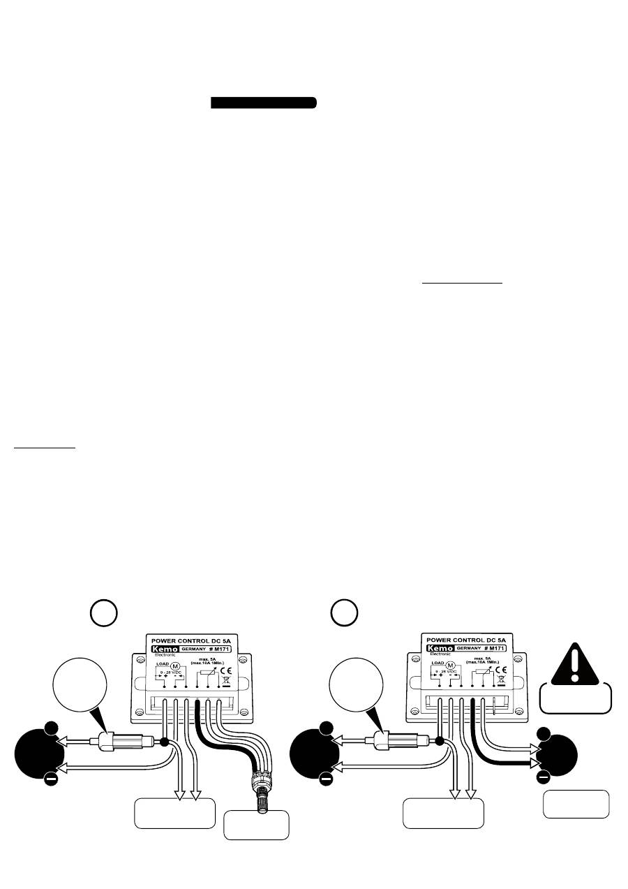
RUS 9 - 28 V/DC 9 - 28 V/DC
• Poti
(beiliegend)
• Poti
(included)
• Steuerspannung
• Control voltage
• ohne Poti!
• without Poti!
• Last
(Motor, Lampe...)
• Load
(motor, lamp...)
• Last
(Motor, Lampe...)
• Load
(motor, lamp...)
+
+
+
D | Leistungsregelung mit Poti GB | Power control with Poti D | Leistungsregelung über Gleichspannung 0 - 5 V GB | Power control over direct current 0 - 5 V
• Sicherung
• Fuse
• Sicherung
• Fuse
10 A
10 A
2
1
• Anschlussbeispiele
• Connection examples
0 - 5
V/DC
