Vitek VT-4073 SR: Remote control 2. PREPARATIONS 2.1 PACKAGE SET 1. DVD player 2.2 Battery installation into the remote control 2.3 SYSTEM CONNECTION
Remote control 2. PREPARATIONS 2.1 PACKAGE SET 1. DVD player 2.2 Battery installation into the remote control 2.3 SYSTEM CONNECTION: Vitek VT-4073 SR
Table of contents
- Operating manual MAINTENANCE RULES IMPORTANT SAFETY NOTICES USAGE NOTICES ON THE DVD PLAYER USAGE NOTICES ON POWER SUPPLY MAIN FEATURES OF THE DEVICE
- 24bit/96Khz Digital/Analog (D/A) converter. Component video output. Laser head overcurrent protecting system 1. Brief instruction of controls Front panel function: Back panel function:
- Remote control 2. PREPARATIONS 2.1 PACKAGE SET 1. DVD player 2.2 Battery installation into the remote control 2.3 SYSTEM CONNECTION
- Channal amplifier Digital audio amplifier 2.4. PLAY MODE SETTING 3. BASIC OPERATION
- 3.1. Disc playing 4. FUNCTIONALITY DESCRIPTION
- 4.2 N/P function 4.3 Subtitles 4.4 OPEN/ 4.5 PBC (PLAYBACK) 4.6 MIC ON/OFF 4.7 ANGLE 4.8 LANGUAGE» 4.9 TITLE 4.10 MENU 4.11. DIRECTION KEYS 4.12 3D FUNCTION 4.13 NUMBER KEYS 4.14 TIME 4.15 REPEAT FROM A TO B
- 4.16 REPEAT FUNCTION 4.17. ZOOM 4.18. PROGRAM 4.19. R/L FUNCTION (SOUND BALANCING) 4.20 VOLUME AND MUTE 4.21. THE “SLOW“ FUNCTION 4.22 VIDEO FUNCTION 5. SETTING UP THE SYSTEM
- 1.1. ANGLE MARK 1.1.3 SCREEN LANGUAGE 1.1.4 HIDE SUBTITLES 1.1.5 SCREEN PROTECTION 1.1.7 MEMORY PLAY SETTINGS
- 1. AUDIO SETUP 1..1 SPEAKER SETUP 1..1.1. DOWNMI� MODE When the center, rear and the subwoofer speaker are in the “Off” 1..1.3 CENTRAL SPEAKER
- 1..1.4 REAR SPEAKER 1..1.5 WOOFER SPEAKER 1.. DIGITAL AUTO SETUP 1...1 DIGITAL AUDIO OUTPUT 1... LPCM OUTPUT
- 1..3. DOLBYDIGITALSETUP 1..3.1 L+R SETUP 1..3. DYNAMIC RANGE COMPRESSION 1..4 EQUALIZER SETUP 1..4.1 EQUALIZER MODE 1..4. BASS ENHANCING 1..4.3 SUB WOOFER
- 1..4.4. TREBLE BOOST 1..5 3D PROCESSING SETUP 1..5.1 PRO LOGIC II SETUP 1..5.1.1 PRO LOGIC II SETUP 1..5.1.. PRO LOGIC II SETUP
- 1..5.1.3. PRO LOGIC II SETUP 1..5.1.4 PRO LOGIC II SETUP 1..5.1.5 PRO LOGIC II SETUP 1..5.1.5. MI�TURE MODE 1..6 MICROPHONE SETUP 1..6.1 MICROPHONE SETUP
- 1..6.1.1 MICROPHONE SETUP 1.3 VIDEO SETUP 1.3.1 COMPONENT 1.3. TV MODE 1.3.3 QUALITY 1.3.3.1 SHARPNESS 1.3.3. BRIGHTNESS 1.3.3.3 CONTRAST 1.4. PREFERENCE SETUP
- 1.4.1 TV TYPE SETUP AUDIO SETUP SUBTITLE SETUP DISC MENU LANGUAGE SETUP PARENTAL CONTROL
- 1.4.6. DEFAULT SETTINGS 1.5. PASSWORD SETUP 1.5.1. PASSWORD SETUP. 1.5.. PASSWORD 6. OPERATING THE МР3 FUNCTION 7. JPEG SETTINGS 8. TROUBLESHOOTING GUIDE 9. DISC PROTECTION
- 10. MPEG 4 OPERATION 11.Technical Specifications
ENGLISH
4
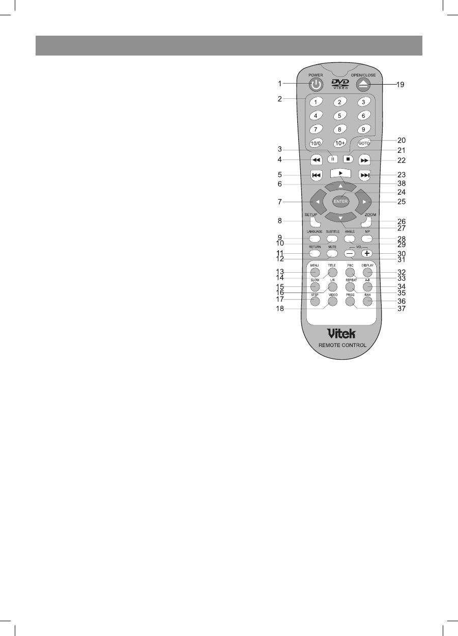
Remote control
• Point the remote control directly at the player’s remote sensor.
• Don’t leave the remote control in an extremely hot or humid place.
• Don’t insert the batteries in the wrong direction.
• If the remote control does not function correctly or the operating range becomes
reduced, replace all batteries with new ones.
1. POWER
. 09, 10+ NUMBER KEYS
3. PAUSE
4. PREV
5. REV
6.UP
7. LEFT
8. SETUP
9. LANGUAGE
10. SUBTITLE
SUBTITLE
11. RETURN
1. MUTE
13. MENU
14. TITLE
TITLE
15. SLOW
16. L/R
17. STEP
18. VIDEO
19. OPEN/CLOSE
/CLOSE
CLOSE
0. GOTO
1. STOP
. NE�T
NE�T
3. FWD
FWD
4. ENTER
5. RIGHT
RIGHT
6. ZOOM
7. DOWN
8. N/P
/P
P
9. ANGLE
ANGLE
30. VOL+
VOL+
+
31. VOL
VOL
3. DISPLAY
33. PBC
34. AB
35. REPEAT
REPEAT
36. RAN
37. PROG
38. PLAY
2. PREPARATIONS
2.1 PACKAGE SET
1. DVD player
. Remote control panel.
3. Audio/video cable.
4. User’s manual.
5. Batteries.
6. Warranty card.
7. Packaging (box).
2.2 Battery installation into the remote control
Place two AAAformat batteries in the battery compartment. Be sure the polarities are correct. There should be no large obstacles between the
remote controller and the main unit.
2.3 SYSTEM CONNECTION
1. When making connection between this unit and other components ensure that all connections are switched off.
. Audio/video cables are connected according to the different colour identification and should be inserted firmly.
a. Yellow cable should be connected to video jack.
b. White cable should be connected to audio jack.
c. Red cable should be connected to audio jack too.
3. Scheme of connection.
4073IM.indd 4
09.10.2007 12:28:30
