Mitsubishi Electric MDT421S: Setup Procedure
Setup Procedure: Mitsubishi Electric MDT421S
English-10
1. Determine the installation location
CAUTION:
DO NOT ATTEMPT TO INSTALL THE LCD MONITOR BY
YOURSELF.
Installing your LCD display must be done by a quali
fi
ed tech-
nician. Contact your dealer for more information.
CAUTION:
MOVING OR INSTALLING THE LCD MONITOR MUST BE
DONE BY TWO OR MORE PEOPLE.
Failure to follow this caution may result in injury if the LCD
monitor falls.
CAUTION:
Do not mount or operate the display upside down or face
down.
CAUTION:
Do not install the LCD monitor where it will be exposed to
direct sunlight, as this will result in display defects.
CAUTION:
This LCD has a temperature sensor and cooling fan. If the
LCD becomes too hot, the cooling fan will turn on automati-
cally. If the LCD becomes overheated and the cooling fan
is running, the “Caution” menu will appear. If the “Caution”
menu appears, discontinue use and allow the unit to cool.
When the LCD monitor is used in an enclosure or with protec-
tion on LCD surface, please check the inside temperature of
monitor by “HEAT STATUS” (See page 31). The temperature is
too hot than normal condition, please set “cooling fan” to ON
on SCREEN SAVER function (See page 28).
IMPORTANT:
Lay the protective sheet, which was wrapped around the LCD
monitor when it was packaged, beneath the LCD monitor so
as not to scratch the panel.
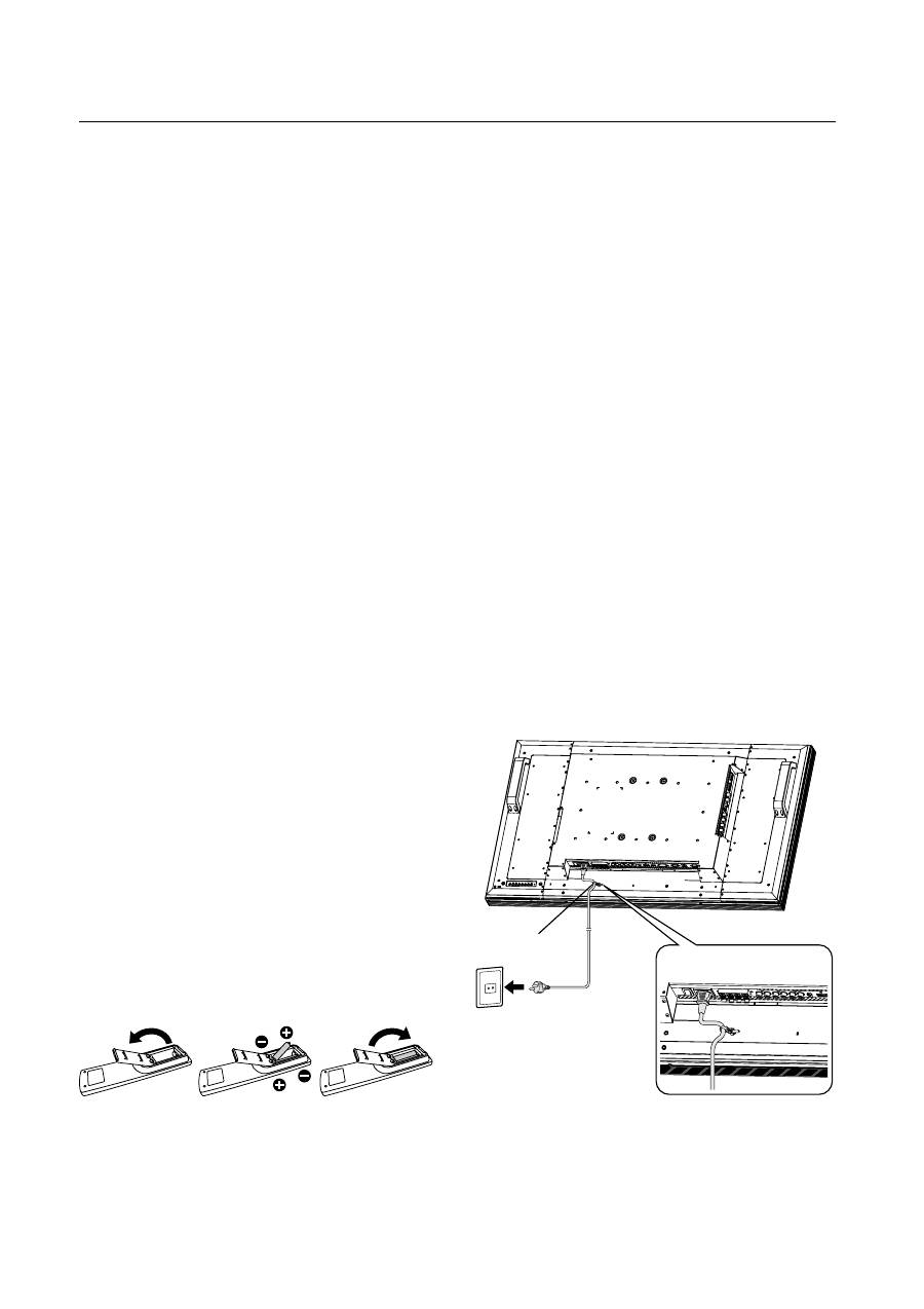
2. Installing and removing the remote
control batteries
The remote control is powered by 1.5V AAA batteries.
To install or replace batteries:
How to install the batteries
1. Unlock and pull up the cover in the arrow’s direction.
2. Align the batteries according to the (+) and (–) indications
inside the case.
3. Replace the cover.
How to remove the batteries
1. Unlock and pull up the cover in the arrow’s direction.
2. Remove the batteries.
CAUTION:
Incorrect use of batteries can result in leaks or bursting.
Be careful especially about the following points.
• Place “AAA” batteries matching the + and - signs on each
battery to the + and - signs of the battery compartment.
• Do not mix battery types.
• Do not combine new batteries with used ones. It causes
shorter battery life or leakage of batteries.
• Remove dead batteries immediately to prevent battery
liquid from leaking into the battery compartment. Don't
touch exposed battery acid, it cause damage to your skin.
NOTE:
If you do not intend to use the Remote Control for a long
period, remove the batteries.
3. Connect external equipment
(See pages 15-19)
• To protect the connected equipment, turn off the main
power before making connections.
• Refer to your equipment user manual.
4. Connect the supplied power cord
• The power outlet socket should be installed as near to the
equipment as possible, and should be easily
accessible.
• Fully insert the prongs into the power outlet socket.
Loose connection may cause noise.
NOTE:
Please refer to “Safety Precautions, Maintenance &
Recommended Use” section of this manual for proper
selection of AC power cord.
5. Switch on the power of all the
attached external equipment
When connected with a computer, switch on the power of the
computer
fi
rst.
Setup Procedure
Clamper
Use the clamper
to secure the
cable firmly.
English
English-11
6. Operate the attached external equipment
Display the signal on the external equipment you wish.
7. Adjust the sound
Make adjustments lowering or rising the volume as required.
8. Adjust the screen (See pages 24-34)
Make adjustments to the display position or settings if re-
quired.
9. Adjust the image (See pages 24-34)
Make adjustments to brightness or contrast if required.
10. Recommended Adjustment
To reduce the risk of “image persistence”, please adjust
the following items based on the application being used.
“POWER SAVE” (See page 28), “SCREEN SAVER” (See
page 28), “SIDE BORDER COLOR”(See page 28), “DATE
AND TIME” (See page 31), “SCHEDULE”(See page 31).
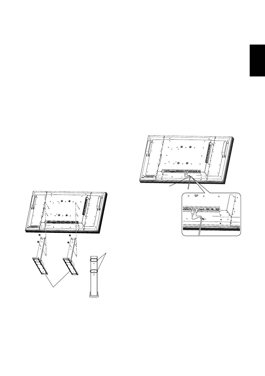
11. Installing and removing the stands
The stands are prepared as option.
Refer to the user’s manual of the stand for more information.
How to install the stands
1. Please turn monitor off.
2. Fasten screws
on both sides of the monitor.
NOTE:
Install the stands so that their longer portions come to the
front.
How to remove the stands
1. Spread the protective sheet on the
fl
at surface, such as a
desk.
2. Place monitor on the protective sheet.
3. Remove screws with a screwdriver and place them in a
safe place for reuse.
12. Connecting HDMI cable and Display
Port cable
Stands
(Longer portion
comes to the front.)
Screw holes for
MDT421S
Clamper
Use the clamper
to secure the
cable firmly.
English-12
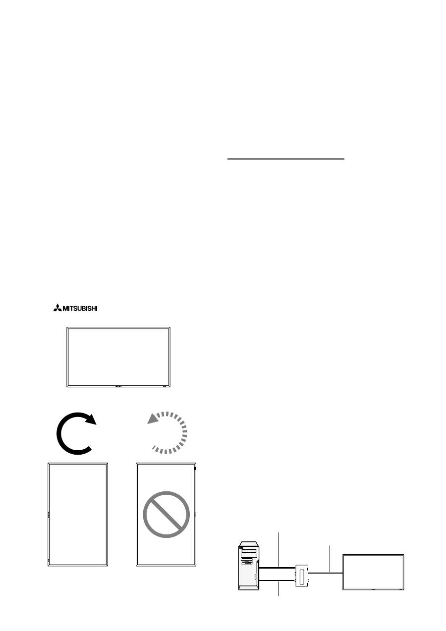
13. When MDT421S is installed in portrait
position
Conditions
MDT421S can be installed in portrait position, under the fol-
lowing conditions:
Caution:
Portrait position is effective only when wall-mounted or
ceiling-mounted.
The stands (legs) can not be
fi
tted to the monitor in portrait
position.
Placing the monitor in portrait position, will shorten the aver-
age life of the LCD backlight.
Operational Environment (Temperature) shall be limited, as
shown below:
Operational
Environment:
Temperature 5 - 35 °C / 41 - 95 °F
Humidity
20 - 80 % (without condensation)
Please orientate the monitor in the direction shown below:
Do not place monitor in landscape in any other manner.
Optional speakers (SP-421S) can not be attached when this
LCD monitor is installed in portrait position.
How to set-up
The “
” logo should be on the LEFT side when
facing the monitor.
MDT421S
MDT421S
90°
90°
Landscape
Counterclockwise
Clockwise
14. For long-distance connection using
the CAT5 Kit
NOTE:
The CAT5 Kit is an option designed for MDT421S. For the de-
tailed mounting procedure, see the user’s guide for the CAT5
Kit (option).
CAT5 video connection
The CAT5 video connection function is for transmitting the
analog RGB video signal of the computer and the control
signal of the monitor over a long distance using CAT5 cables.
The computer can control the monitor via the optional CAT5
Tx BOX and the CAT5 Rx BOX that is mounted on MDT421S.
Caution:
Never connect network devices (such as a hub and a comput-
er for LAN) to the CAT5 IN and OUT connectors of the CAT5
Kit. If they are connected, the network devices themselves,
CAT5 Tx BOX, CAT5 Rx BOX, and monitor may be damaged.
1. Installation of the USB driver for CAT5
serial communication control
To connect the computer and the CAT5 Tx BOX via USB inter-
face, it is necessary to install the USB driver to the computer
from the CD-ROM supplied with the CAT5 Kit (option).
(When connecting the computer and the CAT5 Tx BOX via
RS-232C interface, you don’t have to install the USB driver.)
OS supported: Windows
®
XP, Windows Vista
®
How to install:
1) Installation to Windows
®
XP
Start the “PL2303-Driver_XP2K_v
******
.exe”
fi
le in the
Windows XP folder on the CD-ROM supplied with the CAT5
Kit (option) and install the driver according to the instructions
displayed on the screen.
2) Installation to Windows Vista
®
Start the “PL2303_Proli
fi
c_Vista_
******
.exe”
fi
le in the
Windows VISTA folder on the CD-ROM supplied with the
CAT5 Kit (option) and install the driver according to the in-
structions displayed on the screen.
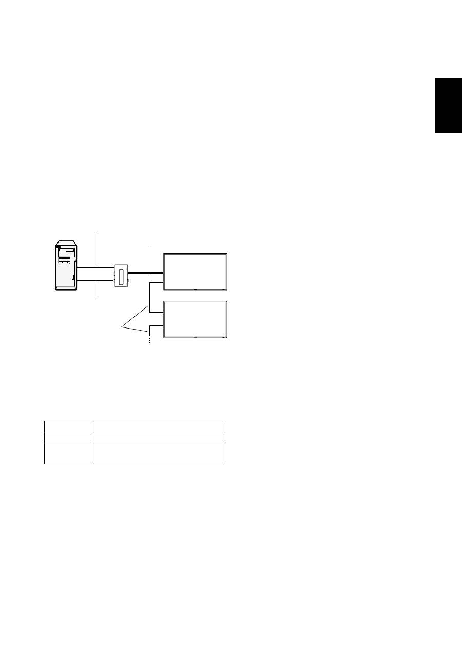
2. Connection of the CAT5 video connec-
tion function
There are two cases of connection.
1) Connection to one monitor
Monitor with CAT5
Rx BOX (option)
Computer
USB cable
CAT5 cable
VGA (mini D-SUB 15-pin) cable (supplied)
CAT5 Tx BOX
(option)
English
English-13
1. Connect the USB connector of the supplied CAT5 Tx BOX
and that of the computer using a commercially available
USB cable. (When the USB driver isn’t available, connect
an RS-232C cable in addition to the USB cable. In this
case, the USB cable serves for supplying the power to the
CAT5 Tx BOX.) See page 35.
2. Connect the D-SUB input connector of the CAT5 Tx BOX
and the VGA (D-SUB) output connector of the computer
using the signal cable (mini D-SUB 15-pin cable) supplied
with the monitor.
3. Connect the modular connector of the CAT5 Tx BOX and
the CAT5 (RGB5) IN connector of the CAT5 Rx BOX using
a commercially available CAT5 cable.
2) Connection to multiple monitors
1. In addition to the connection made step 1) above, con-
nect the CAT5 OUT connector of the
fi
rst monitor and the
CAT5 (RGB5) IN connector of the second monitor using a
commercially available CAT5 cable.
2. Connect the third and later monitors in the same way.
You can connect up to 5 monitors.
Allowable cable length
Connection
Max. cable length/signal timing
One monitor
150 m / 1920 x 1080 @60 Hz
Multiple moni-
tors
200 m / 1920 x 1080 @60 Hz
(Total length of the connected cables)
The lengths given above are based on the actual measure-
ments using our standard signal source and the recommend-
ed cable as follows. Before installation, check the monitor
operation in advance by connecting it with your computer and
cables.
Recommended cable:
8-pin modular connector, straight-through, shielded, Category
5 or 5e
Commercially available cables that passed the compatibility
test (Tested with shielded connectors commercially available.):
7929A of Belden, NFTP-C5e-GY of Nex1
3. Various settings involved in the CAT5
video connection
In the case of the CAT5 video connection, con
fi
gure the fol-
lowing settings displayed on the OSD screen. (See page 29.)
1) CAT5 CABLE LENGTH
Select the cable length, and the defaults of all the adjustment
values are automatically determined.
Select the length that is closest to the actual length of your
cable.
2) CAT5 EQ
Make adjustment so that blur and smear of the displayed let-
ters and graphic objects are minimized.
3) CAT5 R-GAIN/G-GAIN/B-GAIN
When the displayed image is dark, increase each value.
When whites aren’t displayed as intended, adjust the R-GAIN
and B-GAIN values.
4) CAT5 R-SKEW/G-SKEW/B-SKEW
Adjust each value so that the color deviation in the displayed
letters and graphic objects is minimized.
Computer
VGA (mini D-SUB 15-pin)
cable (supplied)
CAT5 cable
Monitor with CAT5
Rx BOX (option)
Monitor supporting
Mitsubishi CAT5
CAT5 Tx BOX
(option)
USB cable
CAT5 cable
Оглавление
- Index
- Important Information
- Safety Precautions, Maintenance & Recommended Use
- Contents
- Parts Name and Functions
- Setup Procedure
- How to Mount and Attach Options to the LCD Monitor
- Connections
- Basic Operation
- OSD (On-Screen-Display) Controls
- Controlling the LCD monitor via RS-232C/RS-485 Remote Control
- Features
- Troubleshooting
- Speci fi cations
- Pin Assignment
- Inhaltsverzeichnis
- Wichtige Informationen
- Sicherheitsvorkehrungen, P fl ege und Einsatzempfehlungen
- Inhalt der Verpackung
- Die Teile und ihre Funktionen
- Einrichten des LCD-Monitors
- Montage und Anbringung von Zubehör am LCD-Monitor
- Anschließen von Geräten
- Grundlegende Bedienung
- OSD-Steuerungen (On-Screen-Display)
- Merkmale und Funktionen
- Fehlerbehebung
- Technische Daten
- Pinbelegung
- Índice
- Información importante
- Medidas de seguridad, mantenimiento y uso recomendado
- Contenido
- Denominación de las piezas y funciones
- Procedimiento de con fi guración
- Cómo montar y conectar elementos opcionales al monitor LCD
- Conexiones
- Funcionamiento básico
- Controles OSD (On-Screen-Display: gestor de pantalla)
- Control del monitor LCD mediante control remoto RS-232C/RS-485
- Características
- Solución de problemas
- Especi fi caciones
- Asignación de PIN
- Index
- Informations importantes
- Informations importantesDéclaration
- Consignes de sécurité, d’entretien, et conseils d’utilisation
- Sommaire
- Noms et fonctions des pièces
- Installation
- Comment monter et brancher des accessoires au moniteur
- Connexions
- Opération de base
- Commandes OSD (On-Screen-Display)
- Fonctionnalités
- Résolution des problèmes
- Spéci fi cations
- Brochage
- Indice
- Informazioni importanti
- Precauzioni di sicurezza, manutenzione e raccomandazioni per l’uso
- Contenuto
- Nome delle parti e delle funzioni
- Procedura di installazione
- Montaggio e collegamento delle opzioni al monitor LCD
- Connessioni
- Operazioni di base
- Controlli OSD (On Screen-Display)
- Controllo del monitor LCD attraverso il controllo remoto RS-232C/RS-485
- Caratteristiche
- Risoluzione dei problemi
- Speci fi che
- Assegnazione spinotti
- Index
- Belangrijke informatie
- Veiligheidsmaatregelen, onderhoud en aanbevolen gebruik
- Inhoud
- Namen en functies van onderdelen
- Installatieprocedure
- Opties voor de LCD-monitor monteren en aansluiten
- Aansluitingen
- Basisbediening
- OSD-besturingselementen (On-Screen-Display)
- Kenmerken
- Problemen oplossen
- Speci fi caties
- Pintoewijzingen
- Указатель
- Важная информация
- Техника безопасности , техническое обслуживание и рекомендации по эксплуатации
- Содержимое
- Названия деталей и их функции
- Процедура установки
- Монтаж и прикрепление деталей к ЖКД монитору
- Выполнение соединений
- Основные операции
- Органы управления OSD (On-Screen-Display)
- Управление ЖКД монитором c помощью коробки дистанционного управления RS-232C/RS-485
- Характеристики
- Устранение неисправностей
- Технические характеристики
- Назначение штырьков
