Mitsubishi Electric MDT421S: OSD (On-Screen-Display) Controls
OSD (On-Screen-Display) Controls: Mitsubishi Electric MDT421S
English
English-23
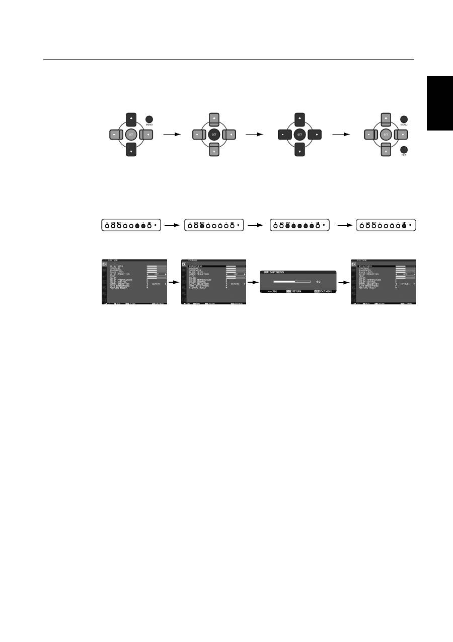
OSD (On-Screen-Display) Controls
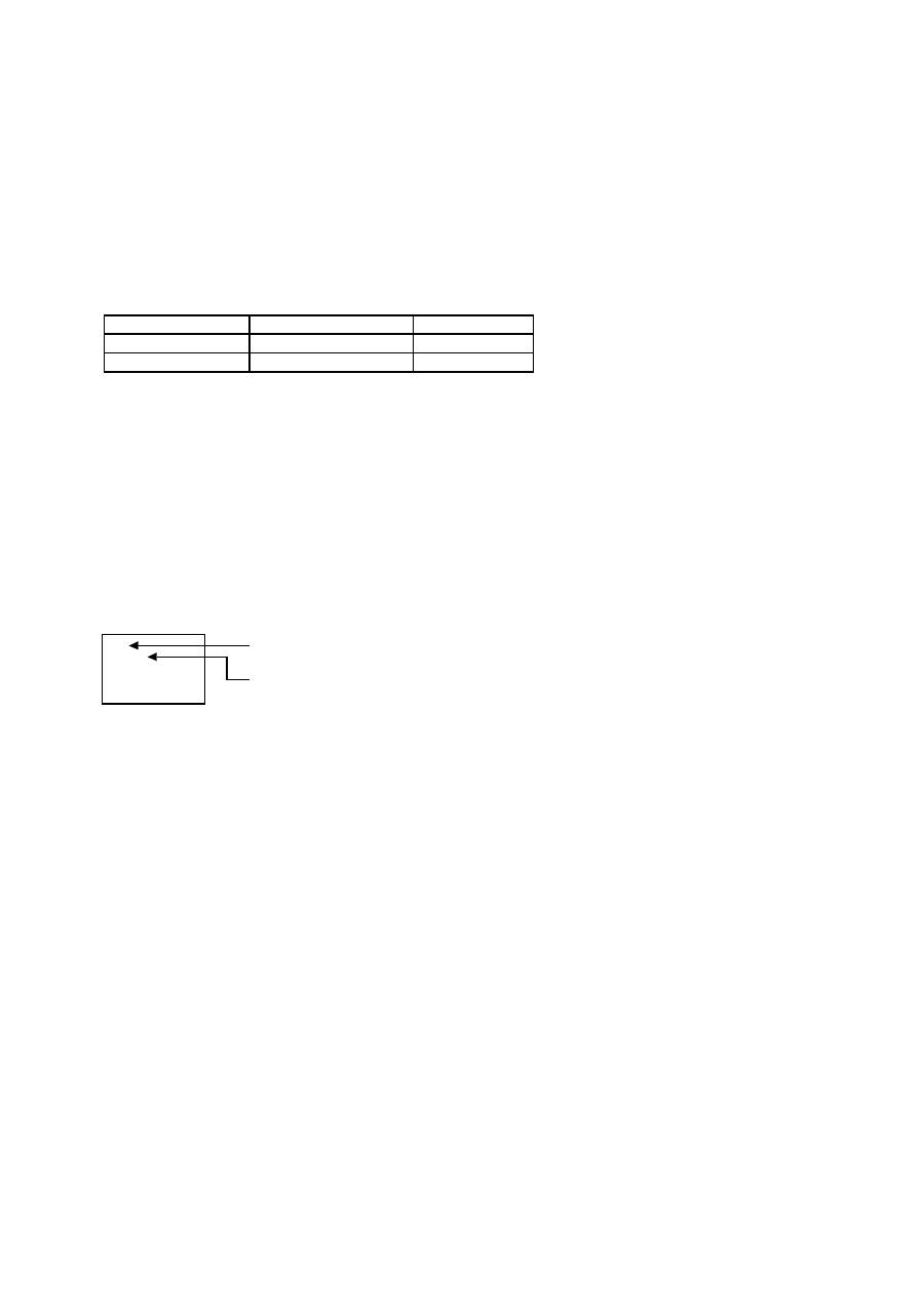
Press MENU button to
open Main menu. Press
UP or DOWN button to
select sub-menu.
Press EXIT button to
open Main menu.
Press UP or DOWN
button to select
sub-menu.
After selecting the sub-menu
using UP or DOWN button
and pressing INPUT button to
enter the selected sub-menu,
make adjustment using PLUS
or MINUS button.
Press INPUT button
to enter the selected
sub-menu.
Press EXIT button to go
back to the previous
menu screen. By pressing
EXIT button at Main-
Menu, Main-Menu
disappears.
Press UP or DOWN, and PLUS
or MINUS button to select
function, or control which you
like.
Press SET button to decide.
Remote Control
Control Panel
OSD screen
Press MENU or EXIT
button to exit.
Press SET button
to decide.
English-24
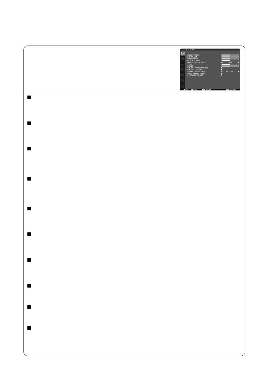
PICTURE
Main-Menu
BRIGHTNESS
Adjusts the overall image and background screen brightness.
Press + button to increase brightness.
Press - button to decrease brightness.
CONTRAST
Adjusts the image brightness in relation to the input signal.
Press + button to increase contrast.
Press - button to decrease contrast.
SHARPNESS
This function is digitally capable to keep crisp image at any timings.
It is adjustable to get a distinct image or a soft one as you prefer and set independently for each picture mode.
Press + button to increase sharpness.
Press - button to decrease sharpness.
BLACK LEVEL
Adjusts the image brightness in relation to the background.
Press + button to increase black level.
Press - button to decrease black level.
NOTE: sRGB picture mode is standard and cannot be changed.
NOISE REDUCTION
* : INPUT RGB1 (HDMI INPUT MODE: HDMI-HD), RGB2 (DVI INPUT MODE: DVI-HD), DVD/HD, VIDEO<S>, VIDEO only
Adjusts the noise reduction level.
Press + button to increase reduction level.
Press - button to decrease reduction level.
TINT
* : INPUT RGB1 (HDMI INPUT MODE: HDMI-HD), RGB2 (DVI INPUT MODE: DVI-HD), DVD/HD, VIDEO<S>, VIDEO only
Adjust the tint of all color, or red, magenta, blue, cyan, green, and yellow individually.
Press + button the flesh tone color becomes greenish.
Press - button the flesh tone color becomes purplish.
COLOR
* : INPUT RGB1 (HDMI INPUT MODE: HDMI-HD), RGB2 (DVI INPUT MODE: DVI-HD), DVD/HD, VIDEO<S>, VIDEO only
Adjust the color saturation of all color, or of red, magenta, blue, cyan, green, and yellow individually.
Press + button to increase color depth.
Press - button to decrease color depth.
COLOR TEMPERATURE
Use to adjust the color temperature.
The image becomes reddish as the color temperature decreases, and it becomes bluish as the color temperature increases.
COLOR CONTROL
The color levels of red, green, and blue are adjusted by the color bars.
R: Red, G: Green, B: Blue
GAMMA SELECTION
Selects a display gamma.
2.2, 2.4, OPTION, S gamma, Native
NOTE: sRGB picture mode is standard and cannot be changed.
Continued on next page.
English
English-25
AUTO BRIGHTNESS
This function controls the screen brightness depending on the ambient light for easy viewing.
In addition, it changes the screen brightness depending on the ambient light and what are displayed on the screen to
reduce power consumption as low as possible.
[AUTO BRIGHTNESS]
LOCAL: The auto brightness function is enabled.
REMOTE: The auto brightness function is enabled. In addition, the monitor enters the intercommunication mode where
multiple monitors are controlled collectively. (See page 33.)
OFF: This function is disabled.
[CONTROL]
PRIMARY: Select this setting to configure the monitor as Master when controlling multiple monitors collectively.
SECONDARY: Select this setting to use the monitor alone or to configure the monitor as Slave when controlling multiple
monitors collectively.
[LIGHT FROM BACK]
YES: Select this setting when there is a light source such lighting equipment and a window behind the monitor.
NO: Select this setting when there is no light source such lighting equipment and a window behind the monitor.
[BACK WALL]
Select the following settings according to the distance between the rear of the monitor and the wall or window.
FAR: The distance is 5 meters or longer.
NEAR: The distance is 5 meters or shorter.
[FRONT SENSOR]
Select ON for normal use.
OFF: Select this setting when the sensor on the front panel is shielded.
[REAR SENSOR]
Select ON for normal use.
OFF: Select this setting when the sensor on the rear panel is shielded.
[SATURATION]
ON: The image saturation is adjusted depending on the ambient light.
OFF: Image saturation isn't adjusted.
[VIDEO DETECT]
ON: The screen brightness varies depending on what are displayed on the screen to reduce power consumption of the
monitor.
OFF: The screen brightness doesn’t vary and the power consumption isn’t reduced.
PICTURE RESET
Selecting Picture reset allows you to reset all OSD settings about PICTURE setting.
Select “Yes” and press “SET” button to restore to factory preset data.
Press “EXIT” button to cancel and then return to the previous menu.
Continued from previous page.
English-26
OFF
H FLIP
V FLIP
Horizontally rotated
Vertically rotated
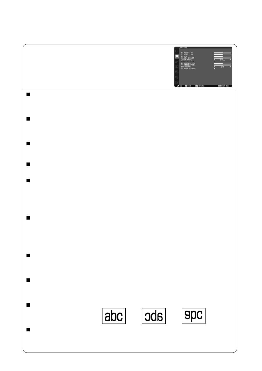
SCREEN
Main-Menu
H POSITION
Controls Horizontal Image position within the display area of the LCD.
Press + button to move screen to right.
Press - button to move screen to left.
V POSITION
Controls Vertical Image position within the display area of the LCD.
Press + button to move screen to UP.
Press - button to move screen to DOWN.
CLOCK
* : INPUT RGB3, 4, 5 only
Press + button to expand the width of the image on the screen the right.
Press - button to narrow the width of the image on the screen the left.
CLOCK PHASE
* : INPUT RGB3, 4, 5 only
Improves focus, clarity and image stability by increasing or decreasing this setting.
ZOOM MODE
You can select “FULL”, “NORMAL” and “CUSTOM” and “REAL”. (INPUT RGB1, 2, 3, 4, 5, 6 only) You can also select “FULL”,
“NORMAL” “DYNAMIC” and “CUSTOM” and “REAL”. (INPUT DVD/HD, VIDEO<S>, VIDEO only)
Selecting “DYNAMIC” will make the screen display panoramic with the expansion of the middle and outside of the screen
changed. (The upper and the bottom of the image will be cut by expansion.)
Dynamic image is the same as FULL size image when HDTV signal is input.
Selecting “REAL” image will be displayed 1 by 1 pixel.
CUSTOM ZOOM
“CUSTOM ZOOM” will be selected when you select “CUSTOM” on the screen “ZOOM” mode.
ZOOM: expands the horizontal and the vertical size simultaneously.
HZOOM: expands the horizontal size only.
VZOOM: expands the vertical size only.
H POSITION: moves to the right with + button. moves to the left with – button.
V POSITION: moves up with + button. moves down with – button.
H RESOLUTION
* : INPUT RGB1, 2, 3, 4, 5, 6 only
Adjusts the horizontal size by increasing or decreasing the setting.
Press + button to expand the width of the image on the screen.
Press - button to narrow the width of the image on the screen.
V RESOLUTION
* : INPUT RGB1, 2, 3, 4, 5, 6 only
Adjusts the vertical size by increasing or decreasing the setting.
Press + button to expand the height of the image on the screen.
Press - button to narrow the height of the image on the screen.
ROTATION
The OSD screen is rotated.
SCREEN RESET
Selecting Screen reset allows you to reset all OSD settings from PICTURE setting.
Select “Yes” and press “SET” button to restore the factory preset data.
Press “EXIT” button to cancel and then return to the previous menu.
English
English-27
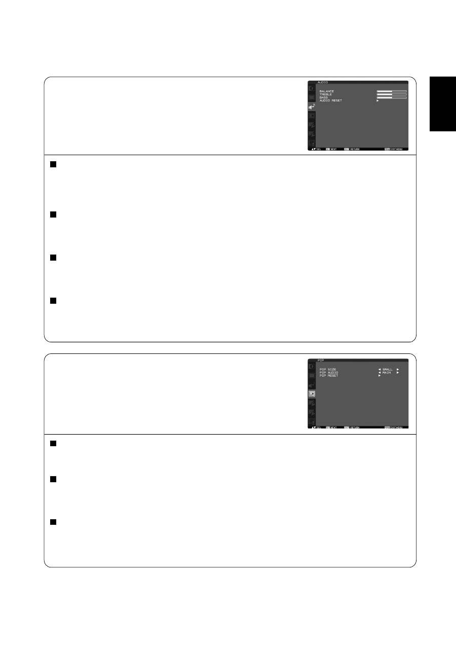
AUDIO
Main-Menu
PIP (PICTURE IN PICTURE)
Note: The “PIP” and “POP” modes do not function when the screen size is “CUSTOM” or “REAL”.
Main-Menu
BALANCE
Adjust the balance of L/R volume.
Press + button to move the stereo sound image to right.
Sound of the left side will be small.
Press - button to move the stereo sound image to left.
TREBLE
To accentuate or reduce the high frequency sound.
Press + button to increase TREBLE sound.
Press - button to decrease TREBLE sound.
BASS
To accentuate or reduce the low frequency sound.
Press + button to increase BASS sound.
Press - button to decrease BASS sound.
AUDIO RESET
Selecting Audio reset allows you to reset all OSD settings from AUDIO setting.
Select “YES” and press “SET” button to restore the factory preset.
Press “EXIT” button to cancel and then return to the previous menu.
PIP SIZE
Selecting the size of picture inserted at the “Picture-in-Picture” (PIP) mode.
“Large”, “Middle” and “Small” are available.
PIP AUDIO
Selecting the sound source in PIP mode.
When selecting “MAIN AUDIO”, you will get the sound for the main picture and when selecting “PIP AUDIO”,
you will get the sound for the picture instead.
PIP RESET
Selecting PIP Reset allows you to reset all OSD settings from PIP setting.
Select “Yes” and press “SET” button to restore the factory preset data.
Press “EXIT” button to cancel and then return to the previous menu.

English-28
CONFIGURATION 1
Main-Menu
AUTO SETUP
* : INPUT RGB3, 4, 5 only
Press “SET” button to automatically adjust screen size, horizontal position, vertical position, clock, clock phase,
white level and black level.
Press “EXIT” button to cancel execution AUTO SETUP and then will return to the previous menu.
AUTO ADJUST
* : INPUT RGB3, 4, 5 only
Selecting the auto adjust ON/OFF.
Selecting ON when changing the timing, the horizontal position, vertical position and clock-phase will adjust automatically.
POWER SAVE
Selecting RGB “ON”, the monitor will go to power management mode when RGB1, 2, 3, 4, 5, 6 sync is lost.
Selecting VIDEO “ON”, the monitor will go to power management mode after about 10 minutes delay from when DVD/HD,
VIDEO<S> and VIDEO input signal is lost.
LANGUAGE
OSD control menus are available in eight languages.
(English, German, Spanish, French, Italian, Swedish, Chinese and Japanese)
SCREEN SAVER
Select “SCREEN SAVER” functions to reduce the risk of the “image persistence”.
GAMMA: The display gamma is changed and fixed when selected “ON”.
COOLING FAN: The built in cooling fan is always on when set “ON”. When “AUTO” is selected, the built-in cooling fan starts
rotating automatically when the internal temperature exceeds the operation guarantee range.
BRIGHTNESS: The brightness is decreased when selected “ON”.
MOTION: Image is slightly expanded and moves 4 directions (UP, DOWN, RIGHT, LEFT) periodically
(Need setting the time for movement).
Movement area is approximately +/- 10mm from original position;
Please locate the important information such as text within 90% area of screen image.
See “IMAGE PERSISTENCE” on page 32 for this function.
PIP and STILL will be disabled when “MOTION” is active.
COLOR SYSTEM
* : INPUT VIDEO<S>, VIDEO only
Selecting the Color System depends on your input video format.
AUTO: NTSC, PAL, SECAM, PAL60 or 4.43 NTSC is automatically selected.
NTSC: Specific selection of NTSC.
PAL: Specific selection of PAL.
SECAM: Specific selection of SECAM.
PAL-60: Specific selection of PAL60.
4.43NTSC: Specific selection of 4.43 NTSC.
SIDE BORDER COLOR
Use to adjust the brightness of the black areas displayed on both sides of 4:3 image.
OFF, 50, and 100 are selectable.
CONFIGURATION RESET
Selecting the CONFIGURATION RESET allows you to reset all configuration settings.
Select “Yes” and press “SET” button to restore the factory preset data.
Press “EXIT” button to cancel and return the previous menu.
FACTORY RESET
Selecting “YES” allows you to reset PICTURE, SCREEN, AUDIO, CONFIGURATION1,2 and ADVANCED OPTION will be back
to factory settings (except LANGUAGE, DATE AND TIME, HDMI INPUT MODE, DVI INPUT MODE, DDC/CI, MONITOR ID and
SCHEDULE).
Select “YES” and press “SET” button to restore the factory preset data. Press “EXIT” button to cancel and return the
previous menu.
English
English-29
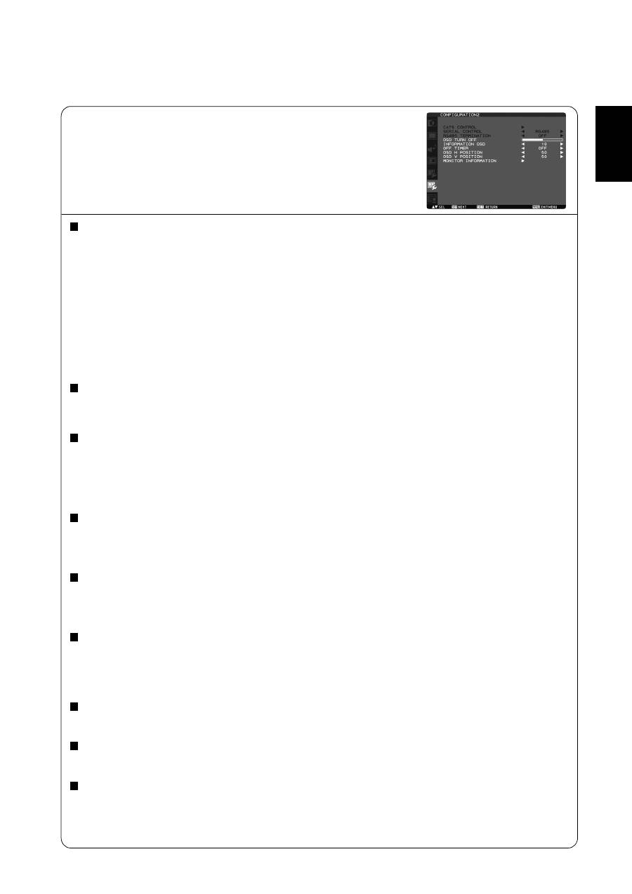
CONFIGURATION 2
Main-Menu
CAT5 CONTROL
* : Selectable only when the optional CAT5 Rx BOX is mounted.
[CAT5 CABLE LENGTH]
Select the cable length, and the defaults of all the adjustment values are automatically determined.
Select the length that is closest to the actual length of your cable.
[CAT5 EQ]
Make adjustment so that blur and smear of the displayed letters and graphic objects are minimized.
[CAT5 R-GAIN, G-GAIN, B-GAIN]
When the displayed image is dark, increase each value.
When whites aren't displayed as intended, adjust the R-GAIN and B-GAIN values.
[CAT5 R-SKEW, G-SKEW, B-SKEW]
Adjust each value so that the color deviation in the displayed letters and graphic objects is minimized.
SERIAL CONTROL
* : Selectable only when the optional CAT5 Rx BOX is mounted.
Select the communication interface (RS232 or RS485) for the serial communication function.
For connection of the signal cable, see page 35.
RS485 TERMINATION
* : Selectable only when the optional CAT5 Rx BOX is mounted.
Turn ON or OFF the termination resistance of the RS-485 interface.
ON: Select this setting to use the monitor alone or to configure the monitor as the one at the end of the connection when more
than one monitor is multi-connected.
OFF: Select this setting to configure the monitor as other than the one at the end of the connection when more than one
monitor is multi-connected.
OSD TURN OFF
The OSD control menu will stay on as long as it is use. In the OSD Turn Off submenu, you can select how long the monitor
waits after the last touch of a button to shut off the OSD control menu.
The preset choices are 5 -120 seconds.
INFORMATION OSD
Selects the information OSD display or not.
The information OSD will display when input signal or source change or warning message like as no-signal or out-of range.
A time between 1 to 10 seconds is available.
OFF TIMER
To select OFF TIMER mode ON/OFF.
In the OFF TIMER menu, you can preset the monitor to automatically power down.
A time between 1 to 24 hours is available.
When the OFF TIMER is set, the SCHEDULE (see page 31) settings will be disabled.
OSD H POSITION
Adjusts the horizontal position of the OSD menu.
OSD V POSITION
Adjusts the vertical position of the OSD menu.
MONITOR INFORMATION
Indicates the model and serial number of your monitor.

English-30
ADVANCED OPTION
Main-Menu
INPUT RESOLUTION
* : INPUT RGB3, 4, 5 only
Selects to decision of input signal about below timings, 1024x768, 1280x768 and 1360x768.
AUTO: Determines the resolution automatically.
1024x768: Determines the resolution as 1024x768
1280x768: Determines the resolution as 1280x768
1360x768: Determines the resolution as 1360x768
The setting you select becomes effective when POWER is turned OFF and ON again.
BLACK LEVEL EXPANSION
* : INPUT RGB1 (HDMI INPUT MODE: HDMI-HD), RGB2 (DVI INPUT MODE: DVI-HD), DVD/HD, VIDEO<S>, VIDEO only
Selects a level of black expansion from “OFF”, “MIDDLE” and “HIGH.”
In case of go under the black cut-off level, please adjust the “Black level” in moderation on OSD menu.
SCAN MODE
* : INPUT RGB1 (HDMI INPUT MODE: HDMI-HD), RGB2 (DVI INPUT MODE: DVI-HD), DVD/HD, VIDEO<S>, VIDEO only
Changes the display area of the image.
OVERSCAN: Set to display area about 95%
UNDERSCAN: Set to display area about 100%
NOTE: When the PIP function is activated, SCAN MODE is forcefully set to OVERSCAN.
SCAN CONVERSION
* : INPUT RGB1 (HDMI INPUT MODE: HDMI-HD), RGB2 (DVI INPUT MODE: DVI-HD), DVD/HD, VIDEO<S>, VIDEO only
Selects IP (Interlace to Progressive) converter function.
PROGRESSIVE: Enable the IP function, to convert interlace signal to progressive. Normally use this setting.
INTERLACE: Disable the IP function.
FILM MODE
Selects Film mode function.
AUTO: Enable the Film mode function. This mode is better suited for movies, which is converted 24 Frames/sec source
to DVD Video. We recommend to select “PROGRESSIVE” in “SCAN CONVERSION”.
OFF: Disable the Film mode function. This mode is better suited for Broadcasting or VCR source.
NOTE: When FILM MODE is AUTO, set SCAN CONVERSION to PROGRESSIVE.
IR CONTROL
Selects the operation mode of the wireless remote controller when multiple MDT421S monitors are connected via RS-232C.
Select from the following four modes using the or button and then accept the selected mode by pressing the SET button.
NORMAL: The monitor will be controlled normally by wireless remote controller.
PRIMARY: The first MDT421S monitor of those multi-connected via RS-232C is designated as PRIMARY.
SECONDARY: MDT421S monitors other than the first one multi-connected via RS-232C are designated as SECONDARY.
LOCK: Disable the monitor control by infrared wireless remote controller.
Keep pressing “DISPLAY” button during 5 sec or more, this setting will return to “NORMAL”.
TILING
TILING demonstrates multiple screens. This feature provides a single large screen using up to 25 monitors.
It will be able to divide up to 5 each H and V.
This requires you to feed the PC output into each of the monitors through a distributor.
H MONITORS: Select number of horizontal divide.
V MONITORS: Select number of vertical divide.
POSITION: Select a position to expand the screen.
FRAME COMP.: Works in tandem with TILING to compensate for the width of the tile bezels in order to accurately
display the image.
ENABLE: Select “YES”, the monitor will expand the selected position.
PIP and STILL will be disabled when “TILING” is activated.
Continued on next page.
English
English-31
HEAT STATUS
Information of status for COOLING FAN, BRIGHTNESS and TEMPERATURE.
COOLING FAN comes to run when inside temperature is over a guaranteed limit.
In this case warning is displayed on the screen.
POWER ON DELAY
Adjusts the delay time from “standby” to “power on” mode.
“POWER ON DELAY” time is selectable from 0-50 seconds.
DATE AND TIME
Adjusts the current date and time for internal clock.
You should set this function when you use “SCHEDULE”.
SCHEDULE
Programs the monitor's working schedule.
Schedule the power on and power off with hour and a day of the week. Also sets the input port.
This OSD can't remove except EXIT.
(See “HOW TO SETUP SCHEDULE” on page 32.)
HDMI INPUT MODE
Select “HDMI-PC” when PC or other computer equipment is connected via HDMI.
Select “HDMI-HD” when DVD player, which has HDMI output, is connected via HDMI.
DVI INPUT MODE
Select “DVI-PC” when PC or other computer equipment is connected via DVI-D.
Select “DVI-HD” when DVD player, which has HDMI output, is connected via DVI-D.
MONITOR ID
ID numbers for remote control are assigned to MDT421S monitors that are multi-connected via RS-232C.
ID numbers 1 to 26 are selectable.
DDC/CI
Use to turn ON or OFF the DDC/CI communication function. Select ON for normal use.
SYNC TYPE
* : INPUT RGB3, 4 only
Select “0.3V” for 0.3 Composite Sync.
Select “TTL” for TTL Sync.
ADVANCED OPTION RESET
Selecting ADVANCED OPTION RESET allows you to reset all OSD settings from ADVANCED OPTION settings,
except for DATE AND TIME, SCHEDULE, HDMI INPUT MODE, DVI INPUT MODE, MONITOR ID, and DDC/CI.
Select “YES” and press “SET” button to restore the factory preset data.
Press “EXIT” button to cancel and then return the previous menu.
Continued from previous page.

English-32
NOTE
< IMAGE PERSISTENCE >
Please be aware that LCD Technology may experience a phenomenon known as Image Persistence. Image Persistence
occurs when residual or “ghost” image of a previous image remains visible on the screen. Unlike CRT monitors, LCD
monitors’ image persistence is not permanent, but constant images being displayed for a long period of time should be
avoided.
To alleviate image persistence, turn off the monitor for as long as the previous image was displayed. For example, if an
image was on the monitor for one hour and a residual image remains, the monitor should be turned off for one hour to erase
the image.
As with all personal display devices, MITSUBISHI ELECTRIC recommends displaying moving images and using a moving
screen saver at regular intervals whenever the screen is idle or turning off the monitor when not in use.
Please set “POWER SAVE”, “SCREEN SAVER”, “DATE AND TIME” and “SCHEDULE” functions to further reduce the risk of
Image persistence.
< For long life use of Public Display >
Image Sticking of LCD Panel
When LCD panel is operated continuously for long hours, a trace of electric charge remains near the electrode inside LCD, and
residual or “ghost” image of previous image may be observed. (Image Persistence)
Image Persistence is not permanent, but when a
fi
xed image is displayed for a long period, ionic impurities inside LCD are
accumulated along the displayed image, and it is observed permanently. (Image Sticking)
Recommendations
For preventing the fast transition to Image Sticking, and for longer life usage of LCD, the following are recommended.
1. Fixed images should not be displayed for long periods of time, and changed to another images with short cycle.
2. When the monitor is not in use, please turn it off using the remote control, use the Power Management Function or use the
Schedule Function.
3. Reducing the environmental temperature is effective for long life use.
When a Protection board (glass, acrylic) is installed over the LCD surface, enclosed into the box / wall, or the monitors are
stacked, please utilize the temperature sensors inside monitor.
To reduce the environmental temperature, the monitor should be set Low Brightness or Cooling Fan “ON” by using the
Screen saver Function.
4. Please use “Screen Saver Mode” of monitor.
< HOW TO SETUP SCHEDULE >
Using the “SCHEDULE” function allows you to set up to seven different scheduled time intervals when the LCD Monitor will be
activated.
You can select the time the monitor turns on and turns off, the day of week the monitor is activated, and which input source the
monitor will use for each scheduled activation period. A check mark in the box next to the number of the schedule
indicates that the selected schedule is in effect.
To select which schedule to set, use the up/down arrows to move the number (1 to 7) of the schedule.
Use the (+) and (-) buttons to move the cursor horizontally within the particular schedule. Use the (
) and (
) buttons to
increase time and select input port. The “SET” button is used to make a selection.
If you create a schedule but do not want to use a power on time, select “--” in the “ON” time slot.
If you do not want to use a power off time select “--” in the OFF time slot.
If there is no input selected (“--” showing in the input spot) the input from the previous schedule will be used.
The selection of EVERY DAY within a schedule takes priority over other schedules that are set up to operate weekly.
When schedules are overlapping, scheduled Power ON time has priority over scheduled Power OFF time.
If there are two schedules programmed for the same time, then the highest numbered schedule has priority.
When the “OFF TIMER” (see page 29) is set, the “SCHEDULE” function is disabled.
English
English-33
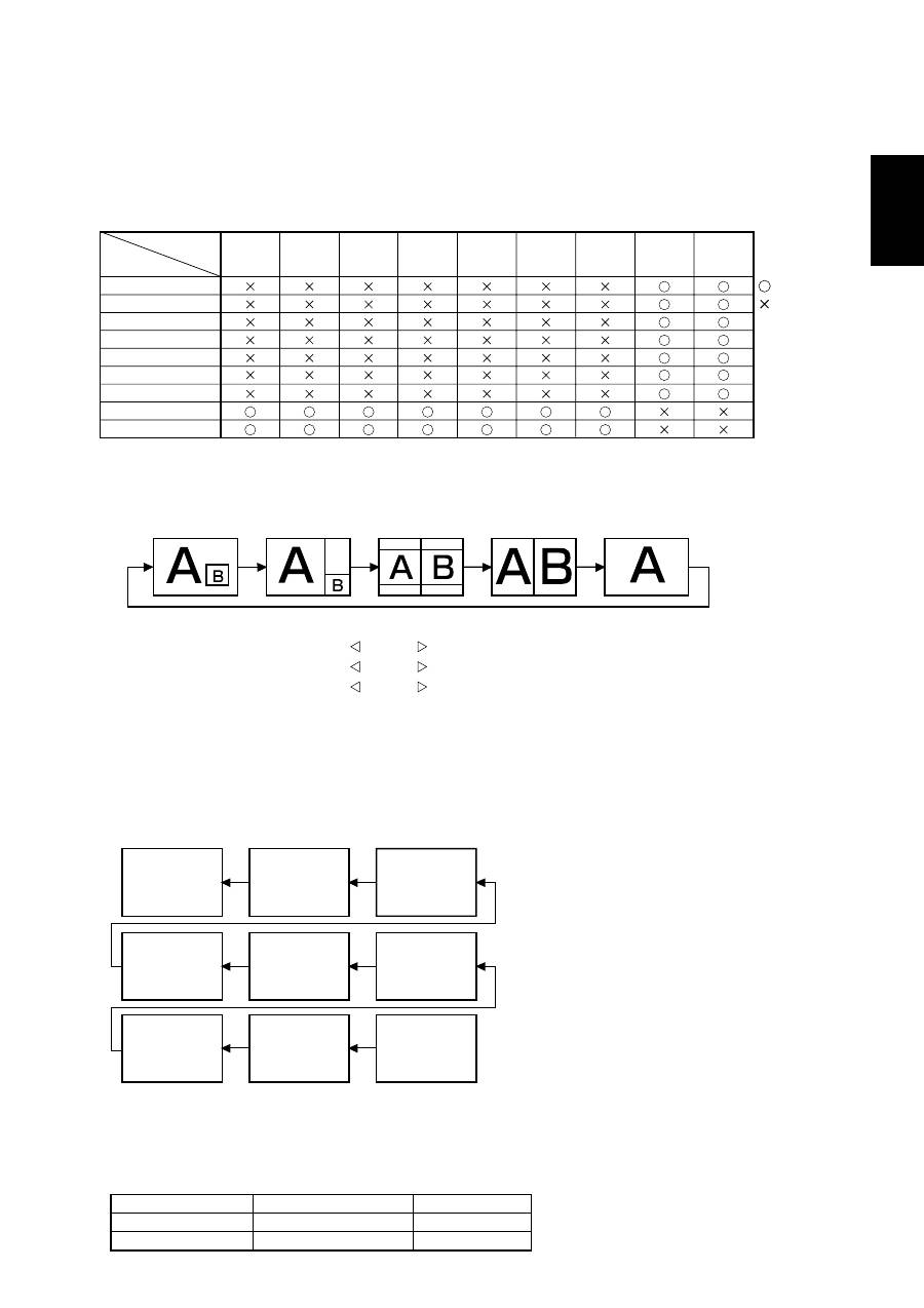
< PIP, POP and SIDE BY SIDE >
The following table shows the combination of signal inputs under which the “PIP” and “POP” modes function. These modes do
not function, however, when the screen size is “CUSTOM” or “REAL”.
< Supplemental information of the auto brightness function >
To control multiple monitors collectively
In such a case where the tiling function is used, you can control the auto brightness function by sharing the detection result of
the brightness sensor of a certain monitor among the connected monitors.
1. Multi-connect the monitors using RS-232C or CAT5 cables separately sold as shown by the example below.
Monitor
ID = 9
(Slave)
Monitor
ID = 8
(Slave)
Monitor
ID = 7
(Slave)
Monitor
ID = 6
(Slave)
Monitor
ID = 5
(Slave)
Monitor
ID = 4
(Slave)
Monitor
ID = 3
(Slave)
Monitor
ID = 2
(Slave)
Monitor
ID = 1
(Master)
Master: Monitor configured as Master that detects
the outside light (Monitor ID is “1”.)
Slave: Monitor controlled by the Master monitor
(Monitor ID is other than “1”.)
2. Assign a monitor ID to each multi-connected MDT421S using MONITOR ID. (See page 31.)
Monitor ID is selectable from 1 to 26.
The monitor ID of the Master monitor should be “1” and those of the Slave monitors should be other than “1”.
You are recommended to assign IDs to the monitors consecutively from 1, 2, 3, and on.
3. Set AUTO BRIGHTNESS on the OSD screen (PICTURE) as follows.
LOCAL
REMOTE
PRIMARY
SECONDARY
Master monitor
Slave monitors
AUTO BRIGHTNESS
CONTROL
RGB1
(HDMI)
RGB1 (HDMI)
RGB2 (DVI-D)
RGB3 (D-SUB)
RGB4 (BNC)
RGB5* (CAT5)
RGB6 (DISPLAY PORT)
DVD/HD (YPbPr)
VIDEO<S>
VIDEO
RGB2
(DVI-D)
RGB3
(D-SUB)
RGB4
(BNC)
RGB5*
(CAT5)
RGB6
(
)
DISPLAY
PORT
DVD/HD
(YPbPr)
VIDEO
VIDEO<S>
SUB
MAIN
: Supported
: Not supported
PIP SIZE
SMALL
MIDDLE
LARGE
: 450 pixels X 338 pixels
: 675 pixels X 450 pixels
: 900 pixels X 675 pixels
: 450 pixels X 338 pixels
POP SIZE
“PIP”, “POP” mode resolution (Reference)
Press the “PIP ON/OFF” buttons on the remote control to change between “PIP”, “POP” and “SIDE BY SIDE”
mode as shown in the diagram below.
PIP
POP
OFF
SIDE BY SIDE
ASPECT
SIDE BY SIDE
FULL
* : RGB 5 becomes usable when the optional CAT5 Rx BOX is mounted.
English-34
To use a computer to control the monitors
When using a computer to control the monitors, you must prepare an application software program for control by yourself.
1. Connect the RS-232C IN connector of the Master monitor shown above and the RS-232C connector of the computer using
an RS-232C cable.
Or, using a CAT5 cable, connect the RS-232C connector of the computer to the CAT5 IN connector of the Master monitor via
the CAT5 Tx BOX.
2. Assign a monitor ID to each multi-connected MDT421S using MONITOR ID. (See step 2 on page 33.)
3. Set AUTO BRIGHTNESS on the OSD screen (PICTURE) as follows.
REMOTE
REMOTE
SECONDARY
SECONDARY
Master monitor
Slave monitors
AUTO BRIGHTNESS
CONTROL
4. For the speci
fi
cations of the communication commands, contact your dealer.
< Remote control numbering function >
By connecting multiple MDT421S monitors using RS-232C cables, you can control any one monitor or all the monitors by one
remote controller.
1. Assign arbitrary ID number to each of multi-connected MDT421S monitors using MONITOR ID.
ID numbers 1 to 26 are selectable.
It is recommended to assign sequential ID numbers from 1 and up.
2. The remote control mode of the
fi
rst MDT421S monitor is set to PRIMARY and those of the other monitors are set to
SECONDARY.
3. When you direct the remote controller at the remote control signal sensor of the PRIMARY monitor and press the DISPLAY
button on the remote controller, the ID selection OSD appears at the upper left of the screen.
ID:1
ID No. :2
Select the ID number of the monitor you want to control using the +/- button
on the remote controller.
The ID of the monitor you want to control is displayed at the upper left of its screen.
By selecting ALL, you can control all the multi-connected monitors.
ID number of the currently viewed monitor
4. Direct the remote controller at the remote control signal sensor of the PRIMARY monitor.
OSD appears on the monitor having the ID number you selected.
NOTE:
When the ID selection OSD is being displayed on the PRIMARY monitor, press the DISPLAY button on the remote controller
again to cancel the ID selection OSD and then control the monitor you selected.
NOTE:
If you set the remote control mode wrongly and remote control operation becomes unavailable, press any button on the control
panel of the monitor to display the OSD screen and change the remote control mode using ADVANCED OPTION. By pressing
and holding down the DISPLAY button on the remote control for 5 seconds or longer, the remote control mode is initialized to
NORMAL.
Оглавление
- Index
- Important Information
- Safety Precautions, Maintenance & Recommended Use
- Contents
- Parts Name and Functions
- Setup Procedure
- How to Mount and Attach Options to the LCD Monitor
- Connections
- Basic Operation
- OSD (On-Screen-Display) Controls
- Controlling the LCD monitor via RS-232C/RS-485 Remote Control
- Features
- Troubleshooting
- Speci fi cations
- Pin Assignment
- Inhaltsverzeichnis
- Wichtige Informationen
- Sicherheitsvorkehrungen, P fl ege und Einsatzempfehlungen
- Inhalt der Verpackung
- Die Teile und ihre Funktionen
- Einrichten des LCD-Monitors
- Montage und Anbringung von Zubehör am LCD-Monitor
- Anschließen von Geräten
- Grundlegende Bedienung
- OSD-Steuerungen (On-Screen-Display)
- Merkmale und Funktionen
- Fehlerbehebung
- Technische Daten
- Pinbelegung
- Índice
- Información importante
- Medidas de seguridad, mantenimiento y uso recomendado
- Contenido
- Denominación de las piezas y funciones
- Procedimiento de con fi guración
- Cómo montar y conectar elementos opcionales al monitor LCD
- Conexiones
- Funcionamiento básico
- Controles OSD (On-Screen-Display: gestor de pantalla)
- Control del monitor LCD mediante control remoto RS-232C/RS-485
- Características
- Solución de problemas
- Especi fi caciones
- Asignación de PIN
- Index
- Informations importantes
- Informations importantesDéclaration
- Consignes de sécurité, d’entretien, et conseils d’utilisation
- Sommaire
- Noms et fonctions des pièces
- Installation
- Comment monter et brancher des accessoires au moniteur
- Connexions
- Opération de base
- Commandes OSD (On-Screen-Display)
- Fonctionnalités
- Résolution des problèmes
- Spéci fi cations
- Brochage
- Indice
- Informazioni importanti
- Precauzioni di sicurezza, manutenzione e raccomandazioni per l’uso
- Contenuto
- Nome delle parti e delle funzioni
- Procedura di installazione
- Montaggio e collegamento delle opzioni al monitor LCD
- Connessioni
- Operazioni di base
- Controlli OSD (On Screen-Display)
- Controllo del monitor LCD attraverso il controllo remoto RS-232C/RS-485
- Caratteristiche
- Risoluzione dei problemi
- Speci fi che
- Assegnazione spinotti
- Index
- Belangrijke informatie
- Veiligheidsmaatregelen, onderhoud en aanbevolen gebruik
- Inhoud
- Namen en functies van onderdelen
- Installatieprocedure
- Opties voor de LCD-monitor monteren en aansluiten
- Aansluitingen
- Basisbediening
- OSD-besturingselementen (On-Screen-Display)
- Kenmerken
- Problemen oplossen
- Speci fi caties
- Pintoewijzingen
- Указатель
- Важная информация
- Техника безопасности , техническое обслуживание и рекомендации по эксплуатации
- Содержимое
- Названия деталей и их функции
- Процедура установки
- Монтаж и прикрепление деталей к ЖКД монитору
- Выполнение соединений
- Основные операции
- Органы управления OSD (On-Screen-Display)
- Управление ЖКД монитором c помощью коробки дистанционного управления RS-232C/RS-485
- Характеристики
- Устранение неисправностей
- Технические характеристики
- Назначение штырьков
