Mitsubishi Electric MDT421S: Parts Name and Functions
Parts Name and Functions: Mitsubishi Electric MDT421S
English-6
ON
OFF
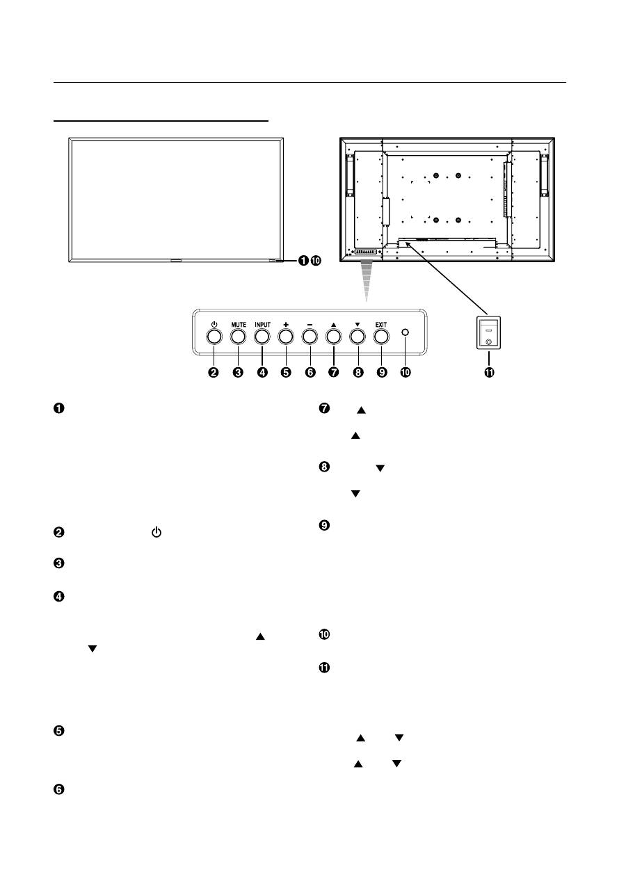
UP (
) button
Activates the OSD menu when the OSD menu is turned-off.
Acts as button to move the highlighted area up to select
the adjustment with OSD menu.
DOWN (
) button
Activates the OSD menu when the OSD menu is turned-off.
Acts as button to move the highlighted area down to select
the adjustment with OSD menu.
EXIT button
Press the EXIT button to display the OSD menu while it isn’t
being displayed.
By pressing this button while the OSD menu is being
displayed, you can move backward through the menu items.
(You can move forward through the menu items using the
INPUT button.) When you press this button at the Main Menu,
the OSD menu disappears. (See page 23.)
Brightness sensor (front, rear)
Sensor for the auto brightness function. (See page 25, 33.)
Main Power Switch
On/Off Switch to turn main power on/off.
NOTE: Control Key Lock Mode
This control completely locks out access to all Control Key
functions. To activate the control key lock function, press
both of “ ” and “
” and hold down simultaneously for
more than 3 seconds. To resume back to user mode, press
both of “ ” and “
” and hold simultaneously for three (3)
seconds.
Remote control sensor and Power indicator
Receives the signal from the remote control (when using the
wireless remote control). See also page 9.
Glows green when the LCD monitor is in active and glows
red when the LCD is in POWER OFF mode. When the LCD is
in power save mode, it will glow both green and red. When
SCHEDULE is enabled, it will blink green and glow red. See
page 21. In the case of where a failure is detected, it will blink
red.
POWER button (
)
Switches the power on/off. See also page 20.
MUTE button
Switches the audio mute ON/OFF.
INPUT button
Displays the OSD menu for switching the video input.
(Select [RGB1], [RGB2], [RGB3], [RGB4], [RGB5]*, [RGB6],
[DVD/HD], [VIDEO<S>] and [VIDEO] using the UP (
) and
DOWN (
) buttons.)
* : [RGB 5] becomes usable when the optional CAT5 Rx BOX
is mounted.
By pressing this button while the OSD menu is being
displayed, you can move forward through the menu items.
(See page 23.)
PLUS (+) button
Acts as (+) button to increase the adjustment with OSD menu.
Increase the audio output level when the OSD menu is turned
off.
MINUS (-) button
Acts as (-) button to decrease the adjustment with OSD menu.
Decreases the audio output level when the OSD menu is
turned off.
Buttons, Switch, and Indicator
Parts Name and Functions
English
English-7
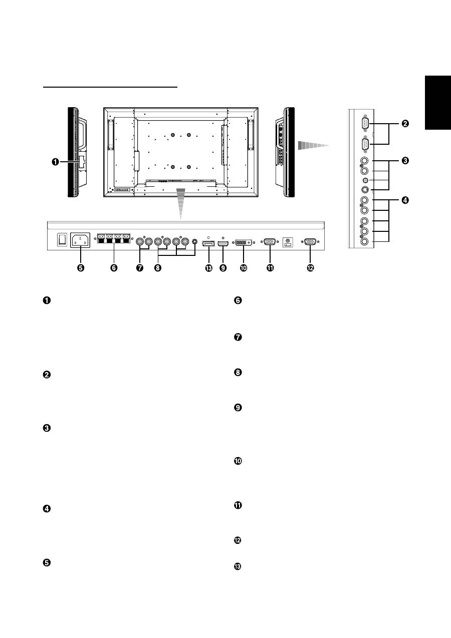
EXTERNAL SPEAKER TERMINAL
To output the audio signal for external speakers from AUDIO 1,
2, 3 jack or HDMI.
AUDIO OUT
To output the audio signal from the AUDIO IN 1, 2, 3 jack or
HDMI.
AUDIO IN 1, 2, 3
To input the audio signal from external equipment such as a
computer, VCR or DVD player.
RGB 1 IN (HDMI)
To input the digital RGB signals from a computer, DVD player,
etc.
* This connector does not support analog input.
AUDIO is supported via HDMI.
RGB 2 IN (DVI-D)
To input the digital RGB signals from a computer.
* This connector does not support analog input.
AUDIO is supported via DVI-D.
RGB 3 IN (mini D-Sub 15 pin)
To input the analog RGB signals from a computer or other
RGB equipment.
RGB OUT (mini D-Sub 15 pin)
To output the signal from RGB 3, 4 or 5 IN.
RGB 6 IN (DISPLAY PORT)
To input the digital RGB signals from a computer.
CAT5 Rx BOX slot
The CAT5 Rx BOX (option) is inserted in this slot. (See page
12.)
NOTE:
Never connect network devices to the CAT5 IN and OUT
connectors. If you do so, they may adversely affect with each
other, causing breakdown.
EXTERNAL CONTROL (mini D-Sub 9 pin)
Connect the IN connector with the RS-232C OUT connector
of the computer or a multi-connected MDT421S monitor.
Connect the OUT connector with the RS-232C IN connector
of a multi-connected MDT421S or MDT521S monitor.
VIDEO IN/OUT
VIDEO IN connector (BNC and RCA):
To input a composite
video signal. BNC and RCA are not available at the same
time. (Use only one input).
VIDEO OUT connector (BNC):
To output the composite
video signal from VIDEO IN connector.
S-VIDEO IN connector (MINI DIN 4 pin):
To input the
S-video (Y/C separate signal).
RGB 4 IN / DVD/HD IN (BNC)
To input the analog RGB signals from a computer or other
RGB equipment.
Connecting equipment such as a DVD player, HDTV device,
or Laser disc player. See page 16, 18.
AC IN connector
Connects with the supplied power cord.
Connectors and Terminals
(OUT)
(IN)
(OUT)
(IN)
(IN)
(IN)
English-8
Wireless Remote Control
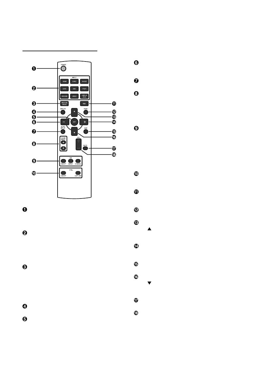
POWER button
Switches the power on/off.
* If LED Power Indicator on the monitor is not glowing, then
no controls will work.
INPUT button
Selects from input signal, [RGB1] (HDMI), [RGB2] (DVI-D),
[RGB3] (D-SUB), [RGB4] (BNC), [RGB5]* (CAT5), [RGB6] (DIS-
PLAY PORT), [DVD/HD] (YPbPr), [VIDEO<S>] and [VIDEO].
* : [RGB 5] becomes usable when the optional CAT5 Rx BOX
is mounted.
PICTURE MODE button
Selects from picture mode, [HIGHBRIGHT], [STANDARD],
[sRGB], [CINEMA]. See page 21.
HIGHBRIGHT:
for moving image such as Video
STANDARD:
for images (Factory setting)
sRGB:
for text based images
CINEMA:
for movies
DISPLAY button
To switch the information OSD on/off. See page 22.
SET button
Acts as SET button with OSD menu.
MINUS button decrease
Acts as (-) button to decrease the adjustment with OSD menu.
Small screen which adjusted “PIP” mode moves left.
AUTO SETUP button
To enter the auto setup menu. See page 28.
AUDIO INPUT button
Press to change the audio source for each video source. The
audio source is changed from [AUDIO1] to [AUDIO2], [AUDIO3]
and [HDMI] in order. Note that you cannot select the audio
source for [VIDEO<S>] or [VIDEO]. [HDMI] is selectable only
when the video source is [RGB 1].
PIP (Picture In Picture) button
ON/OFF button:
PIP-ON/OFF. See page 27, 33.
INPUT button:
Select the “picture in picture” input signal.
CHANGE button:
Replaces to the main picture and sub pic-
ture.
Note:
The “PIP” and “POP” modes do not function when the screen
size is “CUSTOM” or “REAL”.
STILL button
ON/OFF button:
To switch the still picture mode on/off.
CAPTURE button:
Updates the still picture.
SIZE button
Selects picture size, [FULL], [NORMAL], [CUSTOM] , [DY-
NAMIC] and [REAL]. See page 21.
MENU button
To switch the menu mode on/off.
UP button
Acts as button to move the highlighted area up to select
the adjustment with OSD menu.
Small screen which adjusted “PIP” mode moves up.
PLUS button increase
Acts as (+) button to increase the adjustment with OSD menu.
Small screen which adjusted “PIP” mode moves right.
EXIT button
Turn to previous menu with OSD menu.
DOWN button
Acts as button to move the highlighted area down to select
the adjustment with OSD menu.
Small screen which adjusted “PIP” mode moves down.
MUTE button
To switch the mute function on/off.
VOLUME button
Increases or decreases the audio output level.
English
English-9
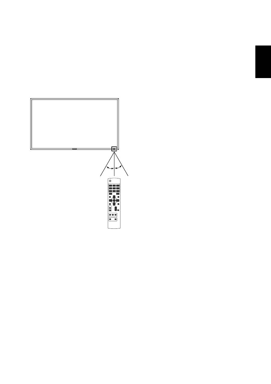
< Operating Range for the Remote
Control >
Point the top of the remote control toward the LCD monitor's
remote sensor during button operation.
Use the remote control within a distance of about 7 m/23 ft.
from the front of the LCD monitor's remote control sensor
and at a horizontal and vertical angle of within 30° within a
distance of about 3 m/10 ft.
CAUTION:
Important, the remote control system may not function when
direct sunlight or strong illumination strikes the remote control
sensor of the LCD monitor, or when there is an object in the
path.
< Handling the remote control >
* Do not subject to strong shock.
* Do not allow water or other liquid to splash the remote
control. If the remote control gets wet, wipe it dry immedi-
ately.
* Avoid exposure to heat and steam.
* Other than to install the batteries, do not open the remote.
30°
30°
Оглавление
- Index
- Important Information
- Safety Precautions, Maintenance & Recommended Use
- Contents
- Parts Name and Functions
- Setup Procedure
- How to Mount and Attach Options to the LCD Monitor
- Connections
- Basic Operation
- OSD (On-Screen-Display) Controls
- Controlling the LCD monitor via RS-232C/RS-485 Remote Control
- Features
- Troubleshooting
- Speci fi cations
- Pin Assignment
- Inhaltsverzeichnis
- Wichtige Informationen
- Sicherheitsvorkehrungen, P fl ege und Einsatzempfehlungen
- Inhalt der Verpackung
- Die Teile und ihre Funktionen
- Einrichten des LCD-Monitors
- Montage und Anbringung von Zubehör am LCD-Monitor
- Anschließen von Geräten
- Grundlegende Bedienung
- OSD-Steuerungen (On-Screen-Display)
- Merkmale und Funktionen
- Fehlerbehebung
- Technische Daten
- Pinbelegung
- Índice
- Información importante
- Medidas de seguridad, mantenimiento y uso recomendado
- Contenido
- Denominación de las piezas y funciones
- Procedimiento de con fi guración
- Cómo montar y conectar elementos opcionales al monitor LCD
- Conexiones
- Funcionamiento básico
- Controles OSD (On-Screen-Display: gestor de pantalla)
- Control del monitor LCD mediante control remoto RS-232C/RS-485
- Características
- Solución de problemas
- Especi fi caciones
- Asignación de PIN
- Index
- Informations importantes
- Informations importantesDéclaration
- Consignes de sécurité, d’entretien, et conseils d’utilisation
- Sommaire
- Noms et fonctions des pièces
- Installation
- Comment monter et brancher des accessoires au moniteur
- Connexions
- Opération de base
- Commandes OSD (On-Screen-Display)
- Fonctionnalités
- Résolution des problèmes
- Spéci fi cations
- Brochage
- Indice
- Informazioni importanti
- Precauzioni di sicurezza, manutenzione e raccomandazioni per l’uso
- Contenuto
- Nome delle parti e delle funzioni
- Procedura di installazione
- Montaggio e collegamento delle opzioni al monitor LCD
- Connessioni
- Operazioni di base
- Controlli OSD (On Screen-Display)
- Controllo del monitor LCD attraverso il controllo remoto RS-232C/RS-485
- Caratteristiche
- Risoluzione dei problemi
- Speci fi che
- Assegnazione spinotti
- Index
- Belangrijke informatie
- Veiligheidsmaatregelen, onderhoud en aanbevolen gebruik
- Inhoud
- Namen en functies van onderdelen
- Installatieprocedure
- Opties voor de LCD-monitor monteren en aansluiten
- Aansluitingen
- Basisbediening
- OSD-besturingselementen (On-Screen-Display)
- Kenmerken
- Problemen oplossen
- Speci fi caties
- Pintoewijzingen
- Указатель
- Важная информация
- Техника безопасности , техническое обслуживание и рекомендации по эксплуатации
- Содержимое
- Названия деталей и их функции
- Процедура установки
- Монтаж и прикрепление деталей к ЖКД монитору
- Выполнение соединений
- Основные операции
- Органы управления OSD (On-Screen-Display)
- Управление ЖКД монитором c помощью коробки дистанционного управления RS-232C/RS-485
- Характеристики
- Устранение неисправностей
- Технические характеристики
- Назначение штырьков
