Mitsubishi Electric MDT421S: Controlling the LCD monitor via RS-232C/RS-485 Remote Control
Controlling the LCD monitor via RS-232C/RS-485 Remote Control: Mitsubishi Electric MDT421S
English
English-35
Controlling the LCD monitor via RS-232C/RS-485 Remote Control
This LCD monitor can be controlled by a personal computer connected with an RS-232C cable or a CAT5 cable via the CAT5 Tx
BOX (option) and CAT5 Rx BOX (option).
Functions that can be controlled by the personal computer are:
• Power ON or OFF
• Switching between input signals
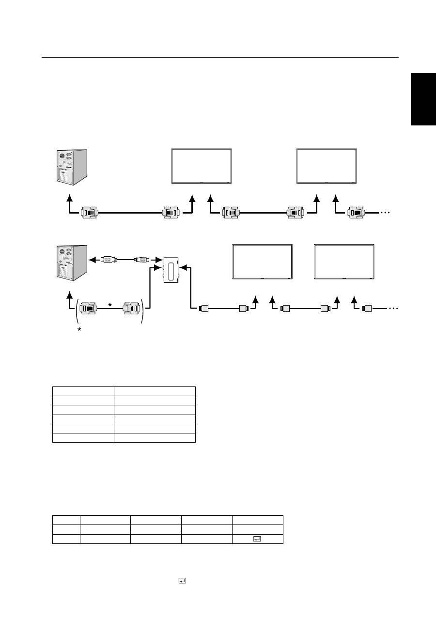
Connection
Connection by RS-232C (For RS-232C cable, the reverse type cable should be used.)
Connection by CAT5 RS-485 (For CAT5 cable, the straight type cable should be used)
NOTE:
If your PC (IBM or IBM compatible) is equipped only with a 25-pin serial port connector, a 25-pin serial port adapter is required.
Contact your dealer for details.
1) Interface
PROTOCOL
BAUD RATE
DATA LENGTH
PARITY BIT
STOP BIT
FLOW CONTROL
RS-232C/RS-485 (CAT5)
9600 [bps]
8 [bits]
NONE
1 [bits]
NONE
This LCD monitor uses RXD, TXD and GND lines for RS-232C control.
2) Control command diagram
The command is structured by the address code, function code, data code and end code. The length of the command is
different for each function.
NOTE:
The example below shows basic commands used for the con
fi
guration consisting of one computer and one monitor (one-to-
one connection). For commands to control multi-connected monitors, contact your dealer in advance.
HEX
ASCII
Address code
30h 30h
‘0’ ‘0’
Function code
Function
Function
Data code
Data
Data
End code
0Dh
[Address code]
30h 30h (In ASCII code, ‘0’ ‘0’)
fi
xed.
[Function code]
A code of each
fi
xed control move.
[Data code]
A code of each
fi
xed control data (number) and not always indicated.
[End code]
0Dh (In ASCII code, ‘ ’ )
fi
xed.
CAT5 Tx BOX
(option)
RS-232C cable
CAT5 cable
To CAT5
OUT
To RS-232C
IN
To CAT5
OUT
To CAT5
RGB5 IN
To CAT5
OUT
To CAT5
RGB5 IN
CAT5 cable
USB cable
Type A
Type B
PC
Monitor with CAT5
Rx BOX (option)
Monitor with CAT5
Rx BOX (option)
This connection isn’t necessary when the USB COM port is used.
PC
RS-232C cable
RS-232C cable
To RS-232C OUT
To RS-232C IN
To RS-232C OUT
To RS-232C IN
Monitor
Monitor
English-36
3) Control sequence
(1) The command from a computer to the LCD monitor will be sent in 600 ms.
(2) The LCD monitor will send a return command 600 ms* after it has received and encoded. If the command isn’t received
correctly, the LCD monitor will not send the return command.
(3) The personal computer checks the command and con
fi
rms if the command, which has been sent, has been executed or
not.
(4) This LCD monitor sends various codes other than return code. When having a control sequence by RS-232C, reject other
codes from personal computers side.
* : The sending time of return command may delay depending on the condition (during changing of the input signal, etc.).
Example: Turn the power ON ( ‘ ’ is for ASCII code)
Meaning
30 30 21 0D
‘0’ ‘0’ ‘!’ ‘ ’
30 30 21 0D
‘0’ ‘0’ ‘!’ ‘ ’
Sending commands
from the PC
Status code from
LCD monitor
Command for
POWER ON
Command received
(Command echoed back)
4) Operation commands
The operation commands execute the basic operation setting of this LCD monitor.
It may not operate when changing the signal:
Operation
ASCII
HEX
POWER ON
!
21h
POWER OFF
"
22h
INPUT RGB 1
_r1
5Fh 72h 31h
INPUT RGB 2
_r2
5Fh 72h 32h
INPUT RGB 3
_r3
5Fh 72h 33h
INPUT RGB 4
_r4
5Fh 72h 34h
INPUT VIDEO
_v1
5Fh 76h 31h
INPUT DVD/HD
_v2
5Fh 76h 32h
INPUT S-VIDEO** _v3
5Fh 76h 33h
INPUT RGB 5*
_r5
5Fh 72h 35h
INPUT RGB 6
_r6
5Fh 72h 36h
• POWER OFF command should be operated over 1 minute after
the power is turned on.
• POWER ON command should be operated over 1 minute after
the power is turned off.
* RGB 5 becomes usable when the optional CAT5 Rx BOX is
mounted.
** S-VIDEO is SEPARATE only
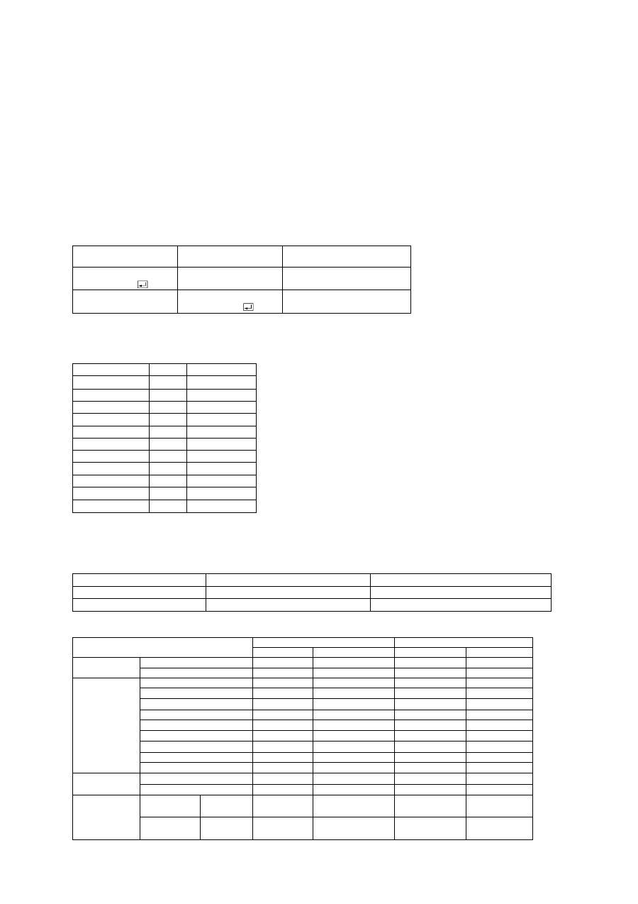
5) Read command
Host computer sends the command without Data-code to monitor.
After receiving this command, the monitor returns the command with Data-code of current status to host computer.
Example: When Host computer ask Power status of monitor, the status of monitor is powered-on.
Command from computer
30 30 76 50 0D ‘0’‘0’‘v’‘P’[enter]
Command from Monitor
Detail of command
Ask about the power status of monitor.
30 30 76 50 31 0D ‘0’‘0’‘v’‘P’‘1’[enter] Monitor is powered-on.
Structure of the Read-command
Function
Data (Receive)
Function
Data (Receive)
ON
vP
vP
1
76 50
31
OFF (stand by)
0
76 50
30
RGB-1 (HDMI)
vI
r1
76 49
72 31
RGB-2 (DVI-D)
vI
r2
76 49
72 32
RGB-3 (D-SUB)
vI
r3
76 49
72 33
RGB-6 (DISPLAY PORT)
RGB-4 (BNC)
vI
r6
76 49
72 36
RGB-5* (CAT5)
* : RGB-5 becomes usable when the optional CAT5 Rx BOX is mounted.
vI
r5
76 49
72 35
vI
r4
76 49
72 34
Video
vI
v1
76 49
76 31
DVD/HD
vI
v2
76 49
76 32
S-VIDEO
vI
v3
76 49
76 33
HIGHBRIGHT
vM
vM
p1
76 4D
70 31
STANDARD
p2
76 4D
70 32
resolution
1
˚
C
resolution
1
˚
C
74 63 31
2B 20 32 35
74 63 32
2B 20 33 31
Input
Picture mode
Temperature
of internal
monitor
Around
Main board
Around
Power PCB
POWER
(ex.) +31
(ex.) +25
tc1
tc2
ASCII
HEX
Оглавление
- Index
- Important Information
- Safety Precautions, Maintenance & Recommended Use
- Contents
- Parts Name and Functions
- Setup Procedure
- How to Mount and Attach Options to the LCD Monitor
- Connections
- Basic Operation
- OSD (On-Screen-Display) Controls
- Controlling the LCD monitor via RS-232C/RS-485 Remote Control
- Features
- Troubleshooting
- Speci fi cations
- Pin Assignment
- Inhaltsverzeichnis
- Wichtige Informationen
- Sicherheitsvorkehrungen, P fl ege und Einsatzempfehlungen
- Inhalt der Verpackung
- Die Teile und ihre Funktionen
- Einrichten des LCD-Monitors
- Montage und Anbringung von Zubehör am LCD-Monitor
- Anschließen von Geräten
- Grundlegende Bedienung
- OSD-Steuerungen (On-Screen-Display)
- Merkmale und Funktionen
- Fehlerbehebung
- Technische Daten
- Pinbelegung
- Índice
- Información importante
- Medidas de seguridad, mantenimiento y uso recomendado
- Contenido
- Denominación de las piezas y funciones
- Procedimiento de con fi guración
- Cómo montar y conectar elementos opcionales al monitor LCD
- Conexiones
- Funcionamiento básico
- Controles OSD (On-Screen-Display: gestor de pantalla)
- Control del monitor LCD mediante control remoto RS-232C/RS-485
- Características
- Solución de problemas
- Especi fi caciones
- Asignación de PIN
- Index
- Informations importantes
- Informations importantesDéclaration
- Consignes de sécurité, d’entretien, et conseils d’utilisation
- Sommaire
- Noms et fonctions des pièces
- Installation
- Comment monter et brancher des accessoires au moniteur
- Connexions
- Opération de base
- Commandes OSD (On-Screen-Display)
- Fonctionnalités
- Résolution des problèmes
- Spéci fi cations
- Brochage
- Indice
- Informazioni importanti
- Precauzioni di sicurezza, manutenzione e raccomandazioni per l’uso
- Contenuto
- Nome delle parti e delle funzioni
- Procedura di installazione
- Montaggio e collegamento delle opzioni al monitor LCD
- Connessioni
- Operazioni di base
- Controlli OSD (On Screen-Display)
- Controllo del monitor LCD attraverso il controllo remoto RS-232C/RS-485
- Caratteristiche
- Risoluzione dei problemi
- Speci fi che
- Assegnazione spinotti
- Index
- Belangrijke informatie
- Veiligheidsmaatregelen, onderhoud en aanbevolen gebruik
- Inhoud
- Namen en functies van onderdelen
- Installatieprocedure
- Opties voor de LCD-monitor monteren en aansluiten
- Aansluitingen
- Basisbediening
- OSD-besturingselementen (On-Screen-Display)
- Kenmerken
- Problemen oplossen
- Speci fi caties
- Pintoewijzingen
- Указатель
- Важная информация
- Техника безопасности , техническое обслуживание и рекомендации по эксплуатации
- Содержимое
- Названия деталей и их функции
- Процедура установки
- Монтаж и прикрепление деталей к ЖКД монитору
- Выполнение соединений
- Основные операции
- Органы управления OSD (On-Screen-Display)
- Управление ЖКД монитором c помощью коробки дистанционного управления RS-232C/RS-485
- Характеристики
- Устранение неисправностей
- Технические характеристики
- Назначение штырьков
