Dell Latitude D520: инструкция
Раздел: Компьютерная техника, комплектующие, аксессуары
Тип: Ноутбук
Инструкция к Ноутбуку Dell Latitude D520
Оглавление
- Dell™Latitude™D520User'sGuide

Dell™Latitude™D520User'sGuide
About Your Computer
Finding Information
Using a Battery
Using the Display
Using the Keyboard and Touch Pad
Using Multimedia
Using Cards
Setting Up a Network
Securing Your Computer
Troubleshooting
System Setup Program
Reinstalling Software
Adding and Replacing Parts
Dell™QuickSet
Traveling With Your Computer
Getting Help
Specifications
Appendix
Glossary
Click the links to the left for information on the features and operation of your computer. For information on other documentation included with your computer,
see Finding Information.
Notes, Notices, and Cautions
Abbreviations and Acronyms
For a complete list of abbreviations and acronyms, see Glossary.
IfyoupurchasedaDell™nSeriescomputer,anyreferencesinthisdocumenttoMicrosoft®
Windows®operating systems are not applicable.
Information in this document is subject to change without notice.
©2006DellInc.Allrightsreserved.
Reproduction in any manner whatsoever without the written permission of Dell Inc. is strictly forbidden.
Trademarks used in this text: Dell, the DELL logo, Inspiron, Dell Precision, Dimension, OptiPlex, Latitude, PowerEdge, PowerVault, PowerApp, ExpressCharge, Dell TravelLite, Undock & Go,
and Dell OpenManage are trademarks of Dell Inc.; Core is a trademark and Intel, Pentium, and Celeron are registered trademarks of Intel Corporation; Microsoft, Outlook, and Windows
are registered trademarks of Microsoft Corporation; Bluetooth is a registered trademark owned by Bluetooth SIG, Inc. and is used by Dell under license; EMC is a registered
trademark of EMC Corporation; ENERGY STAR is a registered trademark of the U.S. Environmental Protection Agency. As an ENERGY STAR partner, Dell Inc. has determined that this
product meets the ENERGY STAR guidelines for energy efficiency.
Other trademarks and trade names may be used in this document to refer to either the entities claiming the marks and names or their products. Dell Inc. disclaims any
proprietary interest in trademarks and trade names other than its own.
Model PP17L
November2006Rev.A01
NOTE: A NOTE indicates important information that helps you make better use of your computer.
NOTICE: A NOTICE indicates either potential damage to hardware or loss of data and tells you how to avoid the problem.
CAUTION: A CAUTION indicates a potential for property damage, personal injury, or death.
Back to Contents Page
About Your Computer
Dell™Latitude™D520User'sGuide
Front View
Left View
Right View
Back View
Bottom View
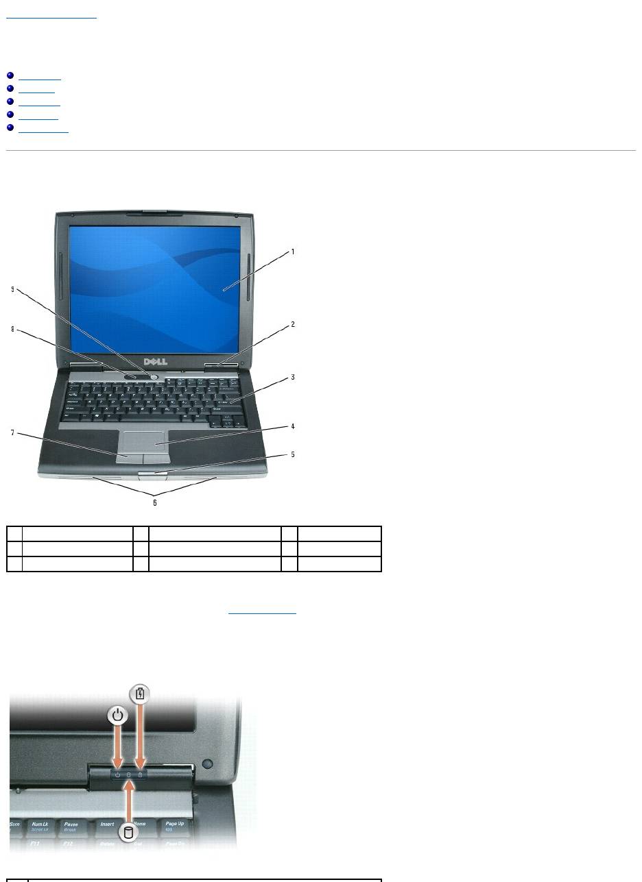
Front View
display — For more information about your display, see Using the Display.
device status lights
1
display
2
device status lights
3
keyboard
4
touch pad
5
display latch
6
speakers
7
touch pad buttons
8
keyboard status lights
9
power button
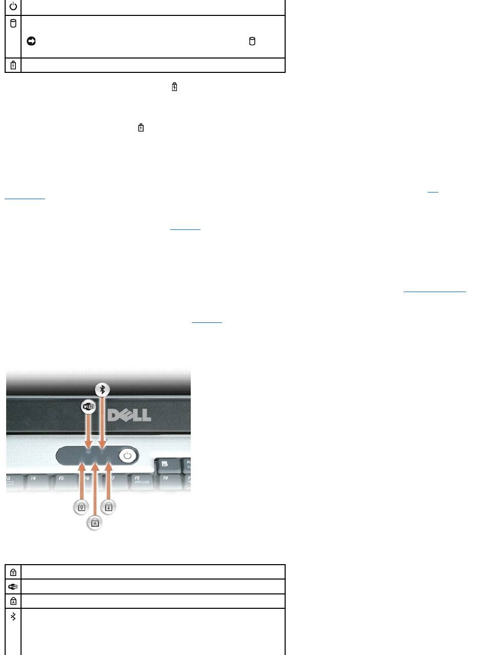
If the computer is connected to an electrical outlet, the light operates as follows:
¡ Solid green: The battery is charging.
¡ Flashing green: The battery is almost fully charged.
If the computer is running on a battery, the light operates as follows:
¡ Off: The battery is adequately charged (or the computer is turned off).
¡ Flashing orange: The battery charge is low.
¡ Solid orange: The battery charge is critically low.
keyboard — The keyboard includes a numeric keypad as well as the Windows logo key. For information on supported keyboard shortcuts, see Key
Combinations.
touch pad — Provides the functionality of a mouse. See Touch Pad for more information.
display latch — Keeps the display closed.
speakers — To adjust the volume of the integrated speakers, press the volume-control keyboard shortcuts. For more information, see Adjusting the Volume.
touch pad buttons — Provide the functionality of a mouse. See Touch Pad for more information.
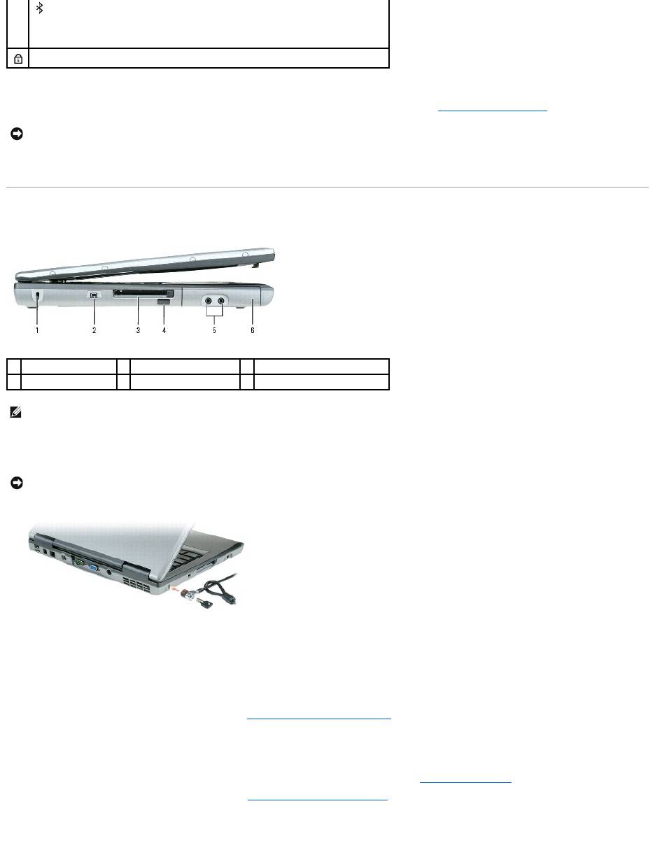
keyboard status lights
The green lights located above the keyboard indicate the following:
Turns on when you turn on the computer and blinks when the computer is in Standby
mode.
Turns on when the computer reads or writes data.
NOTICE: To avoid loss of data, never turn off the computer while the light is
flashing.
Turns on steadily or blinks to indicate battery charge status.
Turns on when the numeric keypad is enabled.
Turns on when wireless devices are enabled.
Turns on when the uppercase letter function is enabled.
Turns on when Bluetooth®wireless technology is enabled. To enable or disable
Bluetooth wireless technology or other wireless devices, press <Fn><F2>.
NOTE: Bluetooth wireless technology is an optional feature on your computer, so the
power button — Press the power button to turn on the computer or exit a power management mode (see Power Management Modes).
If the computer stops responding, press and hold the power button until the computer turns off completely (which may take several seconds).
Left View
security cable slot — Lets you attach a commercially available antitheft device to the computer. For more information, see the instructions included with the
device.
IEEE 1394 Connector — Connects devices supporting IEEE 1394 high-speed transfer rates, such as some digital video cameras.
PC Card/ExpressCard slot — Supports one PC Card, such as a modem or network adapter, or an ExpressCard in an adapter. The computer ships with a
plastic blank installed in the slot. For more information, see Installing a PC Card or ExpressCard.
infrared sensor — Lets you transfer files from your computer to another infrared-compatible device without using cable connections.
When you receive your computer, the sensor is disabled. You can use the system setup program (see System Setup Program) to enable the sensor. For
information on transferring data, see Windows Help, the Help and Support Center, or the documentation that came with your infrared-compatible device. For
information on accessing the Help and Support Center, see Windows Help and Support Center.
audio connectors
icon turns on only if Bluetooth wireless technology is installed on your computer.
For more information, see the documentation that came with your Bluetooth wireless
technology.
Turns on when the scroll lock function is enabled.
NOTICE: To avoid losing data, turn off your computer by performing a Microsoft®Windows®operating system shutdown rather than by pressing the
power button.
1
security cable slot
2
IEEE 1394 connector
3
PC Card/ExpressCard slot
4
infrared sensor
5
audio connectors (2)
6
hard drive
NOTE: The computer turns on the fan when the computer gets hot. Fan noise is normal and does not indicate a problem with the fans or the computer.
NOTICE: Before you buy an antitheft device, ensure that it will work with the security cable slot.
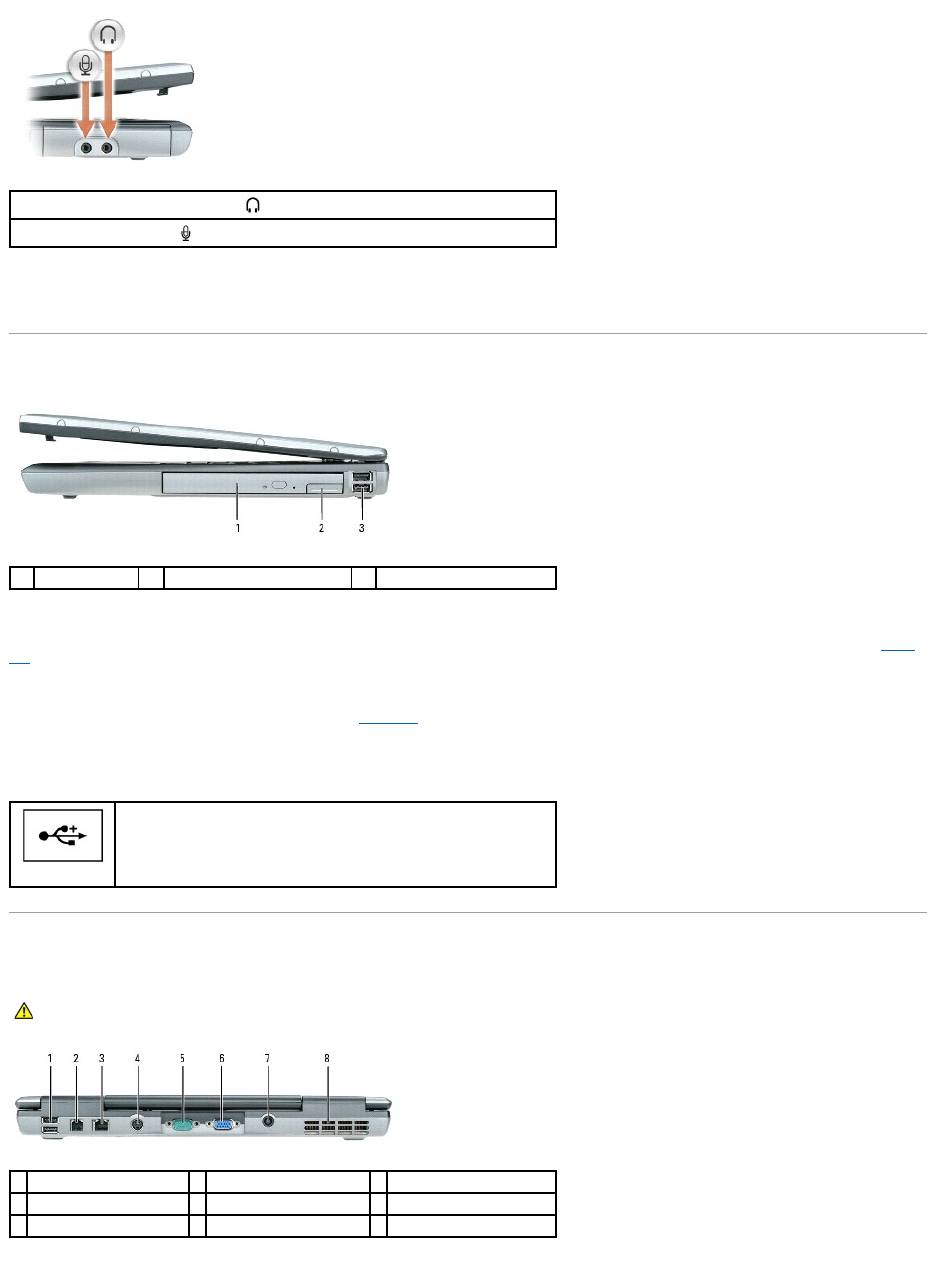
hard drive — Stores software and data.
Right View
media bay — Youcaninstalldevicessuchasanopticaldrive,secondbattery,oraDellTravelLite™moduleinthemediabay.Formoreinformation,seeMedia
Bay.
device latch release — Releases the media bay device. See Media Bay for instructions.
USB connectors
Back View
Attach headphones or speakers to the connector.
Attach a microphone to the connector.
1
media bay
2
device latch release
3
USB connectors (2)
Connect USB devices, such as a mouse, keyboard, or printer. You can also
connect the optional floppy drive directly to a USB connector using the
optional floppy drive cable.
CAUTION: Do not block, push objects into, or allow dust to accumulate in the air vents. Do not store your computer in a low-airflow environment,
such as a closed briefcase, while it is running. Restricting the airflow can damage the computer or cause a fire.
1
USB connectors (2)
2
modem connector (RJ-11)
3
network connector (RJ-45)
4
S-video TV-out connector
5
serial connector
6
video connector
7
AC adapter connector
8
air vents
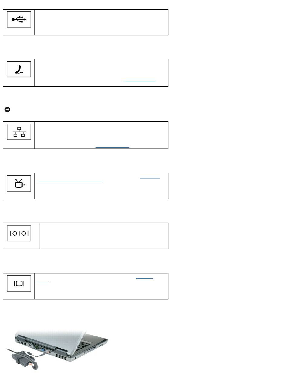
USB connectors
modem connector (RJ-11)
network connector (RJ-45)
S-video TV-out connector
serial connector
video connector
AC adapter connector — Attach an AC adapter to the computer.
The AC adapter converts AC power to the DC power required by the computer. You can connect the AC adapter with your computer turned either on or off.
Connect USB devices, such as a mouse, keyboard, or printer. You can also
connect the optional floppy drive directly to a USB connector using the
optional floppy drive cable.
If you ordered the optional internal modem, connect the telephone line to
the modem connector.
For information on using the modem, see the online modem
documentation supplied with your computer. See Finding Information for
information about accessing online user's guides.
NOTICE: The network connector is slightly larger than the modem connector. To avoid damaging the computer, do not plug a telephone line into the
network connector.
Connects the computer to a network. The two lights next to the connector
indicate the status of both the connection and the transfer of information
for wired network communications.
For information on using the network adapter, see the device user's guide
supplied with your computer. See Finding Information.
Connects your computer to a TV. For more information, see Connecting
Your Computer to a TV or Audio Device.
Connects serial devices, such as a mouse or handheld device.
Connects an external monitor. For more information, see Using the
Display.
air vents — The computer uses an internal fan to create airflow through the vents, which prevents the computer from overheating.
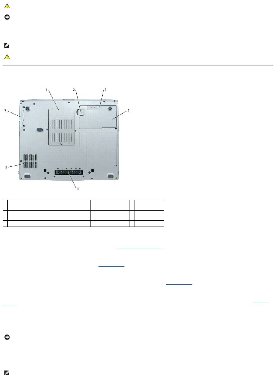
Bottom View
memory module/modem/WLAN Mini-Card/coin-cell battery cover — Covers the compartment that contains one memory module, the modem, the WLAN
Mini-Card, and the coin-cell battery. For additional information, see Adding and Replacing Parts.
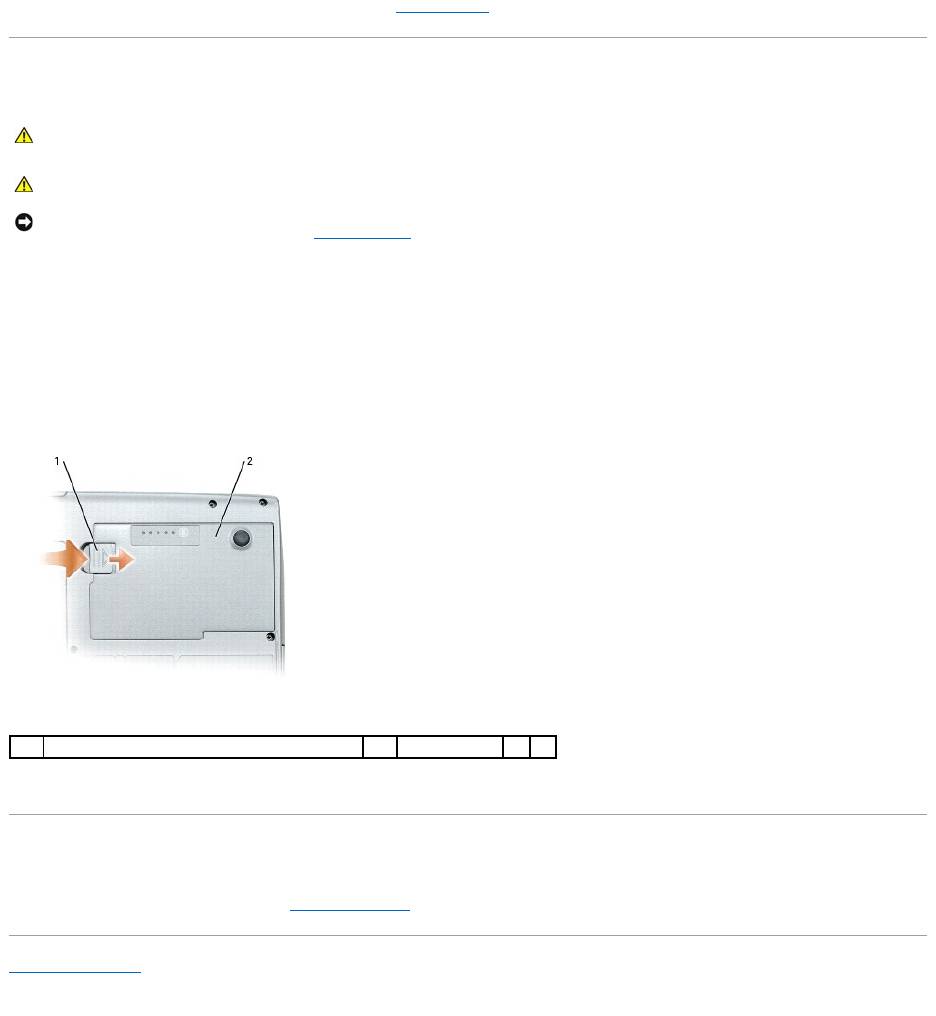
battery-bay latch release — Releases the battery. See Using a Battery for instructions.
battery charge gauge — Provides information on the battery charge. For more information, see Using a Battery.
battery — When a battery is installed, you can use the computer without connecting the computer to an electrical outlet. For more information, see Using a
Battery.
docking device slot — Lets you attach your computer to a docking device. See the documentation that came with your docking device for additional
information.
air vents — The computer uses an internal fan to create airflow through the vents, which prevents the computer from overheating.
CAUTION: The AC adapter works with electrical outlets worldwide. However, power connectors and power strips vary among countries. Using an
incompatible cable or improperly connecting the cable to the power strip or electrical outlet may cause fire or equipment damage.
NOTICE: When you disconnect the AC adapter cable from the computer, grasp the connector, not the cable itself, and pull firmly but gently to avoid
damaging the cable.
NOTE: The computer turns on the fan when the computer gets hot. Fan noise is normal and does not indicate a problem with the fan or the computer.
CAUTION: Do not block, push objects into, or allow dust to accumulate in the air vents. Do not store your computer in a low-airflow environment,
such as a closed briefcase, while it is running. Restricting the airflow can damage the computer or cause a fire.
1
memory module/modem/WLAN Mini-Card/coin-
cell battery cover
2
battery-bay latch
release
3
battery charge
gauge
4
battery
5
docking device
slot
6
air vents
7
hard drive
NOTICE: YourcomputerfeaturesUndock&Go™technologythatallowsyoutoundockyourcomputerwithoutgoingintostandbymode.Becausethe
computer may not automatically go into standby mode when it is undocked, be sure the settings in the Power Options control panel do not prohibit the
computer from going into standby mode. If you change the Power Options control panel to prohibit the computer from going into standby mode, you
greatly increase the chances of causing your battery to wear down quickly or causing your computer to overheat.
NOTE: The computer turns on the fan when the computer gets hot. Fan noise is normal and does not indicate a problem with the fan or the computer.

hard drive — Stores software and data.
Back to Contents Page
CAUTION: Do not block, push objects into, or allow dust to accumulate in the air vents. Do not store your computer in a low-airflow environment,
such as a closed briefcase, while it is running. Restricting the airflow can damage the computer or cause a fire.

Back to Contents Page
Appendix
Dell™Latitude™D520User'sGuide
Cleaning Your Computer
Macrovision Product Notice
FCC Notice (U.S. Only)
Cleaning Your Computer
Computer, Keyboard, and Display
l Use a can of compressed air to remove dust from between the keys on the keyboard.
l Moisten a soft, lint-free cloth with either water or a display cleaner, and wipe the display until it is clean.
l Moisten a soft, lint-free cloth with water and wipe the computer and keyboard. Do not allow water from the cloth to seep between the touch pad and
the surrounding palm rest.
Touch Pad
1. Shut down your computer.
2. Disconnect any attached devices from the computer and from their electrical outlets.
3. Remove any installed batteries (see Replacing the Battery).
4. Moisten a soft, lint-free cloth with water, and wipe it gently across the surface of the touch pad. Do not allow water from the cloth to seep between the
touch pad and the surrounding palm rest.
Floppy Drive
Clean your floppy drive using a commercially available cleaning kit. These kits contain pretreated floppies to remove contaminants that accumulate during
normal operation.
CDs and DVDs
If you notice problems, such as skipping, with the playback quality of your CDs or DVDs, try cleaning the discs.
1. Hold the disc by its outer edge. You can also touch the inside edge of the center hole.
2. With a soft, lint-free cloth, gently wipe the bottom of the disc (the unlabeled side) in a straight line from the center to the outer edge of the disc.
For stubborn dirt, try using water or a diluted solution of water and mild soap. You can also purchase commercial products that clean discs and provide
some protection from dust, fingerprints, and scratches. Cleaning products for CDs are also safe to use on DVDs.
CAUTION: Before you begin any of the procedures in this section, follow the safety instructions in the Product Information Guide.
CAUTION: Before you clean your computer, disconnect the computer from the electrical outlet and remove any installed batteries. Clean your
computer with a soft cloth dampened with water. Do not use liquid or aerosol cleaners, which may contain flammable substances.
NOTICE: To avoid damaging the computer or display, do not spray cleaning solution directly onto the display. Only use products specifically designed for
cleaning displays, and follow the instructions that are included with the product.
NOTICE: Do not attempt to clean drive heads with a swab. You might accidentally misalign the heads which prevents the drive from operating.
NOTICE: Always use compressed air to clean the lens in the CD/DVD drive, and follow the instructions that come with the compressed-air product.
Never touch the lens in the drive.
NOTICE: To avoid damaging the surface, do not wipe in a circular motion around the disc.
Macrovision Product Notice
This product incorporates copyright protection technology that is protected by U.S. patents and other intellectual property rights. Use of this copyright
protection technology must be authorized by Macrovision, and is intended for home and other limited viewing uses only unless otherwise authorized by
Macrovision. Reverse engineering or disassembly is prohibited.
FCC Notice (U.S. Only)
FCC Class B
This equipment generates, uses, and can radiate radio frequency energy and, if not installed and used in accordance with the manufacturer's instruction
manual, may cause interference with radio and television reception. This equipment has been tested and found to comply with the limits for a Class B digital
device pursuant to Part 15 of the FCC Rules.
This device complies with Part 15 of the FCC Rules. Operation is subject to the following two conditions:
1. This device may not cause harmful interference.
2. This device must accept any interference received, including interference that may cause undesired operation.
These limits are designed to provide reasonable protection against harmful interference in a residential installation. However, there is no guarantee that
interference will not occur in a particular installation. If this equipment does cause harmful interference with radio or television reception, which can be
determined by turning the equipment off and on, you are encouraged to try to correct the interference by one or more of the following measures:
l Reorient the receiving antenna.
l Relocate the system with respect to the receiver.
l Move the system away from the receiver.
l Plug the system into a different outlet so that the system and the receiver are on different branch circuits.
If necessary, consult a representative of Dell Inc. or an experienced radio/television technician for additional suggestions.
The following information is provided on the device or devices covered in this document in compliance with the FCC regulations:
Back to Contents Page
NOTICE: The FCC regulations provide that changes or modifications not expressly approved by Dell Inc. could void your authority to operate this
equipment.
Product name:
Dell™Latitude™D520
Model number:
PP17L
Company name:
Dell Inc.
Worldwide Regulatory Compliance & Environmental Affairs
One Dell Way
Round Rock, TX 78682 USA
512-338-4400
Back to Contents Page
Using a Battery
Dell™Latitude™D520User'sGuide
Battery Performance
Checking the Battery Charge
Conserving Battery Power
Power Management Modes
Configuring Power Management Settings
Charging the Battery
Replacing the Battery
Storing a Battery
Battery Performance
ForoptimalcomputerperformanceandtohelppreserveBIOSsettings,operateyourDell™portablecomputerwiththemainbatteryinstalledatalltimes.One
battery is supplied as standard equipment in the battery bay.
Battery operating time varies depending on operating conditions. You can install an optional second battery in the media bay to significantly increase
operating time.
Operating time is significantly reduced when you perform operations including, but not limited to, the following:
l Using optical drives
l Using wireless communications devices, PC Cards, ExpressCards, media memory cards, or USB devices
l Using high-brightness display settings, 3D screen savers, or other power-intensive programs such as 3D games
l Running the computer in maximum performance mode (see Configuring Power Management Settings)
You can check the battery charge before you insert the battery into the computer (see Checking the Battery Charge). You can also set power management
options to alert you when the battery charge is low (see Configuring Power Management Settings).
Checking the Battery Charge
The Dell QuickSet Battery Meter, the Microsoft Windows Power Meter window and icon, the
battery charge gauge and health gauge, and the low-battery warning provide information on the battery charge.
Dell™QuickSetBatteryMeter
If Dell QuickSet is installed, press <Fn><F3> to display the QuickSet Battery Meter. The Battery Meter displays status, battery health, charge level, and charge
completion time for the battery in your computer.
For more information about QuickSet, right-click the icon in the taskbar, and click Help.
NOTE: For information about the Dell warranty for your computer, see the Product Information Guide or separate paper warranty document that shipped
with your computer.
NOTE: Because the battery may not be fully charged, use the AC adapter to connect your new computer to an electrical outlet the first time you use the
computer. For best results, operate the computer with the AC adapter until the battery is fully charged. To view battery charge status, access the
Control Panel® Power Options, and then click the Power Meter tab.
NOTE: Battery operating time (the time the battery can hold a charge) decreases over time. Depending on how often the battery is used and the
conditions under which it is used, you may need to purchase a new battery during the life of your computer.
NOTE: It is recommended that you connect your computer to an electrical outlet when writing to a CD or DVD.
CAUTION: Using an incompatible battery may increase the risk of fire or explosion. Replace the battery only with a compatible battery purchased
from Dell. The lithium ion battery is designed to work with your Dell computer. Do not use a battery from other computers with your computer.
CAUTION: Do not dispose of batteries with household waste. When your battery no longer holds a charge, call your local waste disposal or
environmental agency for advice on disposing of a lithium-ion battery. See "Battery Disposal" in the Product Information Guide.
CAUTION: Misuse of the battery may increase the risk of fire or chemical burn. Do not puncture, incinerate, disassemble, or expose the battery to
temperaturesabove60°C(140°F).Keepthebatteryawayfromchildren.Handledamagedorleakingbatterieswithextremecare.Damaged
batteries may leak and cause personal injury or equipment damage.

Microsoft®Windows®Power Meter
The Windows Power Meter indicates the remaining battery charge. To check the Power Meter, double-click the icon on the taskbar.
If the computer is connected to an electrical outlet, a icon appears.
Charge Gauge
By either pressing once or pressing and holding the status button on the charge gauge on the battery, you can check:
l Battery charge (check by pressing and releasing the status button)
l Battery health (check by pressing and holding the status button)
The battery operating time is largely determined by the number of times it is charged. After hundreds of charge and discharge cycles, batteries lose some
charge capacity—or battery health. That is, a battery can show a status of "charged" but maintain a reduced charge capacity (health).
Check the Battery Charge
To check the battery charge, press and release the status button on the battery charge gauge to illuminate the charge-level lights. Each light represents
approximately 20 percent of the total battery charge. For example, if the battery has 80 percent of its charge remaining, four of the lights are on. If no lights
appear, the battery has no charge.
Check the Battery Health
To check the battery health using the charge gauge, press and holdthestatusbuttononthebatterychargegaugeforatleast3seconds.Ifnolightsappear,
the battery is in good condition, and more than 80 percent of its original charge capacity remains. Each light represents incremental degradation. If five lights
appear,lessthan60percentofthechargecapacityremains,andyoushouldconsiderreplacingthebattery.SeeSpecifications for more information about the
battery operating time.
Low-Battery Warning
By default, a pop-up window warns you when the battery charge is approximately 90 percent depleted. You can change the settings for the battery alarms in
QuickSet or the Power Options Properties window. See Configuring Power Management Settings for information about accessing QuickSet or the Power
Options Properties window.
Conserving Battery Power
Perform the following actions to conserve battery power:
l Connect the computer to an electrical outlet when possible because battery life is largely determined by the number of times the battery is used and
recharged.
l Place the computer in standby mode or hibernate mode when you leave the computer unattended for long periods of time (see Power Management
Modes).
l Use the Power Management Wizard to select options to optimize your computer's power usage. These options can also be set to change when you
press the power button, close the display, or press <Fn><Esc>.
Power Management Modes
Standby Mode
Standby mode conserves power by turning off the display and the hard drive after a predetermined period of inactivity (a time-out). When the computer exits
standby mode, it returns to the same operating state it was in before entering standby mode.
NOTE: You can check battery health in one of two ways: by using the charge gauge on the battery as described below and by using the Battery Meter
in Dell QuickSet. For information about QuickSet, right-click the icon in the taskbar, and click Help.
NOTICE: To avoid losing or corrupting data, save your work immediately after a low-battery warning. Then connect the computer to an electrical outlet.
If the battery runs completely out of power, hibernate mode begins automatically.
NOTE: See Power Management Modes for more information on conserving battery power.

To enter standby mode:
l Click Start® Shut Down® Stand by.
or
l Depending on how you set the power management options in the Power Options Properties window or the QuickSet Power Management Wizard, use
one of the following methods:
¡ Press the power button.
¡ Close the display.
¡ Press <Fn><Esc>.
To exit standby mode, press the power button or open the display depending on how you set the power management options. You cannot make the computer
exit standby mode by pressing a key or touching the touch pad.
Hibernate Mode
Hibernate mode conserves power by copying system data to a reserved area on the hard drive and then completely turning off the computer. When the
computer exits hibernate mode, it returns to the same operating state it was in before entering hibernate mode.
Your computer enters hibernate mode if the battery charge level becomes critically low.
To manually enter hibernate mode:
l Click Start® Turn off computer, press and hold <Shift>, and then click Hibernate.
or
l Depending on how you set the power management options in the Power Options Properties window or the QuickSet Power Management Wizard, use
one of the following methods to enter hibernate mode:
¡ Press the power button.
¡ Close the display.
¡ Press <Fn><Esc>.
To exit hibernate mode, press the power button. The computer may take a short time to exit hibernate mode. You cannot make the computer exit hibernate
mode by pressing a key or touching the touch pad. For more information on hibernate mode, see the documentation that came with your operating system.
Configuring Power Management Settings
You can use the QuickSet Power Management Wizard or Windows Power Options Properties to configure the power management settings on your computer.
l To access the QuickSet Power Management Wizard, double-click the icon in the taskbar. For more information about QuickSet, click the Help button
in the Power Management Wizard.
l To access the Power Options Properties window, click the Start button® Control Panel® Performance and Maintenance® Power Options. For
information on any field in the Power Options Properties window, click the question mark icon on the title bar and then click on the area where you need
information.
Charging the Battery
When you connect the computer to an electrical outlet or install a battery while the computer is connected to an electrical outlet, the computer checks the
battery charge and temperature. If necessary, the AC adapter then charges the battery and maintains the battery charge.
If the battery is hot from being used in your computer or being in a hot environment, the battery may not charge when you connect the computer to an
electrical outlet.
The battery is too hot to start charging if the light flashes alternately green and orange. Disconnect the computer from the electrical outlet and allow the
computer and the battery to cool to room temperature. Then connect the computer to an electrical outlet to continue charging the battery.
NOTICE: If your computer loses AC and battery power while in standby mode, it may lose data.
NOTICE: You cannot remove devices or undock your computer while your computer is in hibernate mode.
NOTE: Some PC Cards or ExpressCards may not operate correctly after the computer exits hibernate mode. Remove and reinsert the card (see
Installing a PC Card or ExpressCard), or simply restart (reboot) your computer.
NOTE: WithDell™ExpressCharge™,whenthecomputeristurnedoff,theACadapterchargesacompletelydischargedbatteryto80percentinabout1
hour and to 100 percent in approximately 2 hours. Charge time is longer with the computer turned on. You can leave the battery in the computer for as
long as you like. The battery's internal circuitry prevents the battery from overcharging.
For more information about resolving problems with a battery, see Power Problems.
Replacing the Battery
To remove the battery:
1. If the computer is connected to a docking device (docked), undock it. See the documentation that came with your docking device for instructions.
2. Ensure that the computer is turned off.
3. Slide the battery-bay latch release on the bottom of the computer until the release clicks.
4. Using the tab on the battery, lift the battery out of the computer.
To replace the battery, place the battery in the bay and press down until the battery-bay latch release clicks.
Storing a Battery
Remove the battery when you store your computer for an extended period of time. A battery discharges during prolonged storage. After a long storage period,
recharge the battery fully before you use it (see Charging the Battery).
Back to Contents Page
CAUTION: Before performing these procedures, turn off the computer, disconnect the AC adapter from the electrical outlet and the computer,
disconnect the modem from the wall connector and computer, and remove any other external cables from the computer.
CAUTION: Using an incompatible battery may increase the risk of fire or explosion. Replace the battery only with a compatible battery purchased
fromDell.ThebatteryisdesignedtoworkwithyourDell™computer.Donotuseabatteryfromothercomputerswithyourcomputer.
NOTICE: You must remove all external cables from the computer to avoid possible connector damage. For information about replacing the second
battery, which is located in the media bay, see Using Multimedia.
1
battery-bay latch release
2
battery
Back to Contents Page
Using Cards
Dell™Latitude™D520User'sGuide
Card Types
Card Blanks
Extended Cards
Installing a PC Card or ExpressCard
Removing a Card or Blank
Card Types
See Specifications for information on supported card types.
The PC Card/ExpressCard slot has one connector that supports a single Type I or Type II card, as well as an adapter for a 34-mm ExpressCard. The PC
Card/ExpressCard slot supports CardBus technology and extended PC Cards. "Type" of card refers to its thickness, not its functionality.
Card Blanks
Your computer shipped with a plastic blank installed in the card slots. Blanks protect unused slots from dust and other particles. Save the blank for use when
no card is installed in the slot; blanks from other computers may not fit your computer. To remove the blank, see Removing a Card or Blank.
Extended Cards
An extended card (for example, a wireless network adapter) is longer than a standard card and extends outside the computer. Follow these precautions when
using extended cards:
l Protect the exposed end of an installed card. Striking the end of the card can damage the system board.
l Always remove an extended card before you pack the computer in its carrying case.
Installing a PC Card or ExpressCard
You can install a PC Card or 34-mm ExpressCard (with an adapter) in the computer while the computer is running. The computer automatically detects the
card.
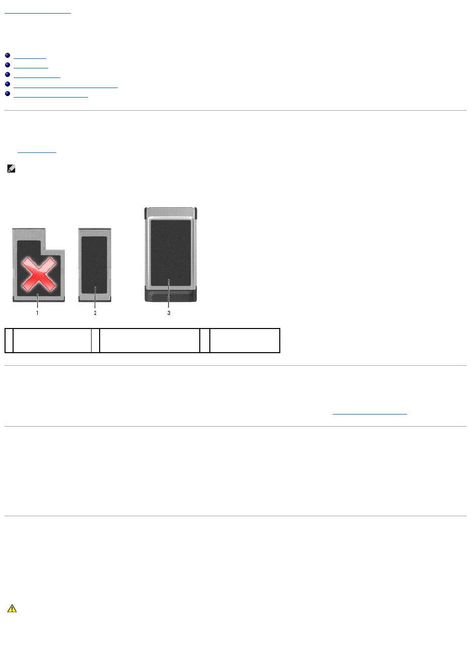
Cards are generally marked with a symbol (such as a triangle or an arrow) to indicate which end to insert into the slot. The cards are keyed to prevent
incorrect insertion. If card orientation is not clear, see the documentation that came with the card.
PC Card
NOTE: A PC Card is not a bootable device.
1
54-mm ExpressCard
(not supported with your
computer)
2
34-mm ExpressCard (supported,
with an adapter)
3
PCCard
(supported with your
computer)
CAUTION: Before you begin any of the procedures in this section, follow the safety instructions in the Product Information Guide.
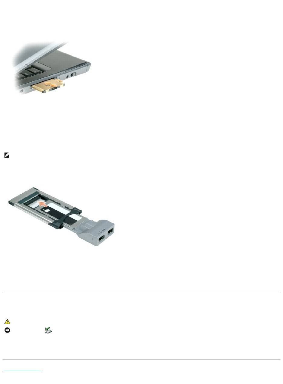
1. Hold the card with its orientation symbol pointing into the slot and the top side of the card facing up. The latch may need to be in the "in" position
before you insert the card.
2. Slide the card into the slot until the card is completely seated in its connector.
If you encounter too much resistance, do not force the card. Check the card orientation and try again.
The computer recognizes most cards and automatically loads the appropriate device driver. If the configuration program tells you to load the manufacturer's
drivers, use the floppy disk or CD that came with the PC Card.
ExpressCard
1. With the 34-mm ExpressCard inserted into its adapter, hold the card with its orientation symbol pointing into the PC Card/ExpressCard slot and the top
side of the card facing up. The latch may need to be in the "in" position before you insert the card.
2. Slide the adapter into the card slot until the adapter is completely seated in its connector.
If you encounter too much resistance, do not force the adapter. Check the ExpressCard and adapter orientation and try again.
The computer recognizes most cards and automatically loads the appropriate device driver. If the configuration program tells you to load the manufacturer's
drivers, use the floppy disk or CD that came with the card.
Removing a Card or Blank
Press the latch and remove the card or blank. For some latches, you must press the latch twice: once to pop the latch out, and then a second time to pop the
card out.
Back to Contents Page
NOTE: Your computer supports a 34-mm ExpressCard only with the use of an adapter. Your computer does not support the use of 54-mm ExpressCards.
CAUTION: Before you begin any of the procedures in this section, follow the safety instructions in your Product Information Guide.
NOTICE: Click the icon in the taskbar) to select a card and stop it from functioning before you remove it from the computer. If you do not stop the
card in the configuration utility, you could lose data. Do not attempt to eject a card by pulling its cable, if one is attached.

Back to Contents Page
Using the Display
Dell™Latitude™D520User'sGuide
Adjusting Brightness
Switching the Video Image
Setting Display Resolution and Refresh Rate
Dual Independent Display Mode
Swapping Primary and Secondary Displays
Adjusting Brightness
WhenaDell™computerisrunningonbatterypower,youcanconservepowerbysettingthebrightnesstothelowestcomfortablesettingbypressing<Fn>
and the up- or down-arrow key on the keyboard.
You can press the following keys to adjust display brightness:
l Press <Fn> and the up-arrow key to increase brightness on the integrated display only (not on an external monitor).
l Press <Fn> and the down-arrow key to decrease brightness on the integrated display only (not on an external monitor).
Switching the Video Image
When you start the computer with an external device (such as an external monitor or projector) attached and turned on, the image may appear on either the
computer display or the external device.
Press <Fn><F8> to switch the video image between the display only, the external device only, or the display and the external device simultaneously.
Setting Display Resolution and Refresh Rate
To display a program at a specific resolution, both the graphics card and the display must support the program, and the necessary video drivers must be
installed.
Before you change any of the default display settings, make a note of the default settings for future reference.
If you choose a resolution or color palette that is higher than the display supports, the settings adjust automatically to the closest supported values.
1. Click Start® Control Panel® Display® Settings.
2. Try different settings for Color quality and Screen resolution.
If the video resolution setting is higher than that supported by the display, the computer enters pan mode. In pan mode, the entire screen cannot be
displayed at one time. For example, the taskbar that usually appears at the bottom of the desktop may no longer be visible. To view the rest of the screen,
use the touch pad to pan up, down, left, and right.
Dual Independent Display Mode
You can attach an external monitor or projector to your computer and use it as an extension of your display (known as "dual independent display" or
"extended desktop" mode). This mode allows you to use both screens independently and drag objects from one screen to the other, effectively doubling the
amount of viewable work space.
NOTE: Brightness key combinations only affect the display on your portable computer, not monitors or projectors that you attach to your portable
computer or docking device. If your computer is connected to an external monitor and you try to change the brightness level, the Brightness Meter may
appear, but the brightness level on the external device does not change.
NOTE: If you change the display resolution from the current settings, the image may appear blurry or text may be hard to read. Before you change
display settings, note the current settings for future reference.
NOTE: Use only the Dell-installed video drivers, which are designed to offer the best performance with your Dell-installed operating system.
NOTE: As the resolution increases, icons and text appear smaller on the screen.
NOTICE: You can damage an external monitor by using an unsupported refresh rate. Before adjusting the refresh rate on an external monitor, see the
user's guide for the monitor.

1. Connect the external monitor, TV, or projector to the computer.
2. Click Start® Control Panel® Display® Settings.
3. Click the monitor 2 icon® Extend my Windows desktop onto this monitor® Apply.
4. Change Screen resolution to the appropriate sizes for both displays and click Apply.
5. If prompted to restart the computer, click Apply the new color setting without restarting® OK.
6. If prompted, click OK to resize your desktop.
7. If prompted, click Yes to keep the settings.
8. Click OK to close the Display Properties window.
To disable dual independent display mode:
1. Click Settings in the Display Properties window.
2. Click the monitor 2 icon, uncheck the Extend my Windows desktop onto this monitor option, and click Apply.
If necessary, press <Fn><F8> to bring the screen image back to the computer display.
Swapping Primary and Secondary Displays
To swap your primary and secondary display designations (for example, to use your external monitor as your primary display after docking):
1. Click Start® Control Panel® Display® Settings® Advanced® Displays.
See the documentation that came with your video card for additional information.
Back to Contents Page
NOTE: If you choose a resolution or color palette that is higher than the display supports, the settings adjust automatically to the closest supported
values. For more information, see your operating system documentation.
Back to Contents Page
Finding Information
Dell™Latitude™D520User'sGuide
NOTE: Some features or media may be optional and may not ship with your computer. Some features or media may not be available in certain countries.
NOTE: Additional information may ship with your computer.
What Are You Looking For?
Find It Here
l A diagnostic program for my computer
l Drivers for my computer
l My device documentation
l Notebook System Software (NSS)
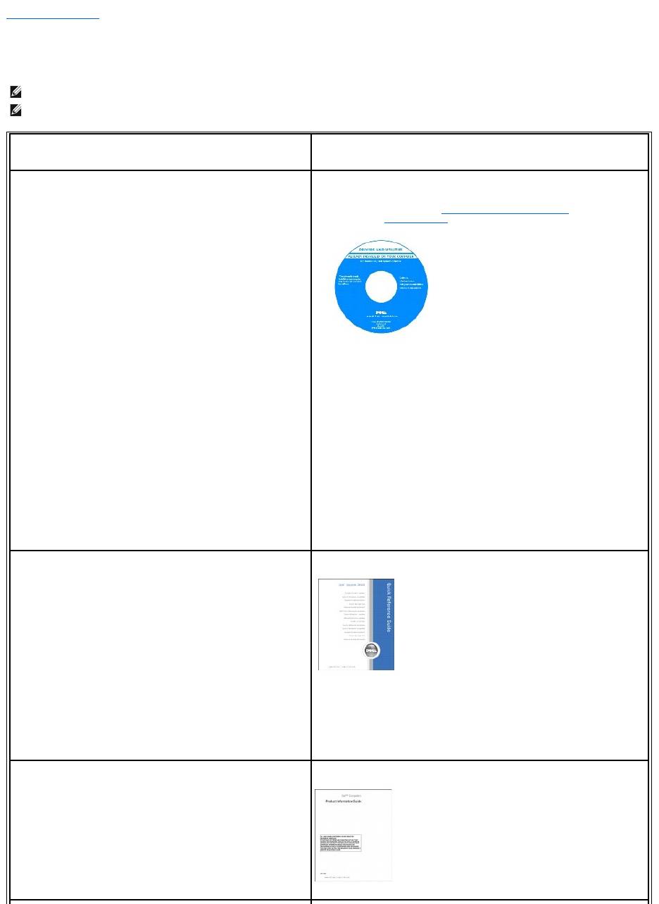
Drivers and Utilities CD (also known as ResourceCD)
Documentation and drivers are already installed on your computer. You can use
the CD to reinstall drivers (see Reinstalling Drivers and Utilities), run the Dell
Diagnostics (see Dell Diagnostics), or access your documentation.
Readme files may be included on your CD to provide last-minute updates about
technical changes to your computer or advanced technical-reference material for
technicians or experienced users.
NOTE: Drivers and documentation updates can be found at support.dell.com.
NOTE: The Drivers and Utilities CD may be optional and may not ship with your
computer.
l How to set up my computer
l Basic troubleshooting information
l How to run the Dell Diagnostics
l How to remove and install parts
Quick Reference Guide
NOTE: This document may be optional and may not ship with your computer.
NOTE: This document is available as a PDF at support.dell.com.
l Warranty information
l Terms and Conditions (U.S. only)
l Safety instructions
l Regulatory information
l Ergonomics information
l End User License Agreement
Dell™ProductInformationGuide
l How to remove and replace parts
l Specifications
l How to configure system settings
l How to troubleshoot and solve problems
User's Guide
Microsoft Windows XP Help and Support Center
1. Click Start® Help and Support® Dell User and System Guides® System
Guides.
2. Click the User's Guide for your computer in the list of online
documentation.
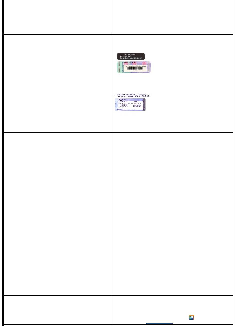
l Service Tag and Express Service Code
l Microsoft Windows License Label
Service Tag and Microsoft®Windows®License
These labels are located on your computer.
l Use the Service Tag to identify your computer when you use
support.dell.com or contact support.
l Enter the Express Service Code to direct your call when contacting
support.
l Solutions — Troubleshooting hints and tips, articles from
technicians, and online courses, frequently asked questions
l Community — Online discussion with other Dell customers
l Upgrades — Upgrade information for components, such as
memory, the hard drive, and the operating system
l Customer Care — Contact information, service call and order
status, warranty, and repair information
l Service and support — Service call status and support history,
service contract, online discussions with support
l Reference — Computer documentation, details on my computer
configuration, product specifications, and white papers
l Downloads — Certified drivers, patches, and software updates
l Notebook System Software (NSS) — If you reinstall the operating
system for your computer, you should also reinstall the NSS utility.
NSS provides critical updates for your operating system and
supportforDell™3.5-inch USB floppy drives, Intel®processors,
optical drives, and USB devices. NSS is necessary for correct
operation of your Dell computer. The software automatically
detects your computer and operating system and installs the
updates appropriate for your configuration.
Dell Support Website — support.dell.com
NOTE: Select your region or business segment to view the appropriate support
site.
To download Notebook System Software:
1. Go to support.dell.com, select your region or business segment, and
enter your Service Tag.
2. Select Drivers & Downloads and click Go.
3. Click your operating system and search for the keyword Notebook System
Software.
NOTE: The support.dell.com user interface may vary depending on your
selections.
l Software upgrades and troubleshooting hints
l Frequently asked questions, hot topics, and general health of
your computing environment
Dell Support Utility
The Dell Support Utility is an automated upgrade and notification system installed
on your computer. This support provides real-time health scans of your
computing environment, software updates, and relevant self-support
information. Access the Dell Support Utility from the icon in the taskbar. For
more information, see Dell Support Utility.
