AEG DI7490-M: INSTALLATION
INSTALLATION: AEG DI7490-M

INSTALLATION
20
INSTALLATION
Drilling the Ceiling/shelf and fixing the frame
• Useaplumblinetomarkthecentreofthehobontheceiling/supportshelf.
• Placethedrillingtemplate21 provided on the ceiling/support shelf, making sure that the tem-
plate is in the correct position by lining up the axes of the template with those of the hob.
• Markthecentresoftheholesinthetemplate.
• Drilltheholesatthepointsmarked:
• Forconcreteceilings,drillforplugsappropriatetothescrewsize.
• Forhollowbrickceilingswithwallthicknessof20mm:drillø10mm(immediatelyinsertthe
Dowels 11 supplied).
• Forwoodenbeamceilings,drillaccordingtothewoodscrewsused.
• Forwoodenshelf,drillø7mm.
• Forthepowersupplycablefeed,drillø10mm.
• Fortheairoutlet(DuctedVersion),drillaccordingtothediameteroftheexternalairexhaust
duct connection.
• Inserttwoscrewsofthefollowingtype,crossingthemandleaving4-5mmfromtheceiling:
• Forconcreteceilings,usetheappropriateplugsforthescrewsize(notprovided).
• forCavityceilingwithinnerspace,withwallthicknessofapprox.20mm,Screws12h, sup-
plied.
• Forwoodenbeamceilings,use4woodscrews(notprovided).
• Forwoodenshelf,use4screws12g with washers 22 and nuts 23, provided.

21
INSTALLATION
FIXING THE FRAME
• Loosenthetwoscrewsfasteningthelowerchim-
ney and remove this from the lower frame.
• Loosenthetwoscrewsfasteningtheupperchim-
ney and remove this from the upper frame.
Ifyouwishtoadjusttheheightoftheframe,proceed
as follows:
• Unfasten the metric screwsjoining the two col-
umns, located at the sides of the frame.
• Adjusttheframetotheheightrequired,thenre-
place all the screws removed as above.
• Insert the upper chimney stack fromabove, and
leave it running free on the frame.
• Lift up the frame, fit the frame slots onto the
screws up to the slot end positions.
• Tightenthetwoscrewsandfastentheothertwo
screws provi-ded with the hood.
Before tightening the screws completely it is possible
toadjusttheframebyturningit.Makesurethatthe
screws do not come out of their seats in the slotted
holes.
• Theframemountingsmustbesecuretowithstand
the weight of the hood and any stresses caused by
the occasional side thrust applied to the device.
On completion, check that the base is stable, even
iftheframeissubjectedtobending.
• Inallcaseswheretheceilingisnotstrongenough
at the suspension point, the installer must provide
strengthening using suitable plates and backing
pieces anchored to the structurally sound parts.
INSTALLATION
22
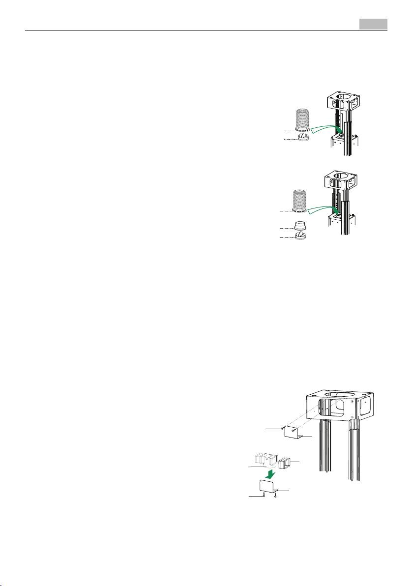
CONNECTION IN DUCTING VERSION
When installing the ducting version, connect the
hood to the chimney using either a flexible or rigid
pipe ø 150 or 120 mm, the choice of which is left
to the installer.
To install a ø 150
• Toinstallthedumper10.
• Fixthepipeinpositionusingsufficientpipeclamps
(not supplied).
To install a ø 120
• Toinstallaø120mmairexhaustconnection,insert
the reducer flange 9 on the dumper 10.
• Fixthepipeinpositionusingsufficientpipeclamps
(not supplied).
• Removeanyactivatedcharcoalfilters.
CONNECTION IN RECYCLING VERSION
• InserttheConnectorextensions14.1intothesideof
the Connector 15.
• InserttheConnector15intotheSupportbracket7.3
and fix it with the screws.
• FastentheSupportbracket7.3,fixingittotheupper
part with the Screws.
• Make sure that the Connector extensions outlet
14.1 is in correspondence with the Chimney open-
ings both horizontally and vertically.
• Join the Connector15totheHoodcanopyoutlet
usingarigidorflexiblepipeø¸150mm,selectionof
which is at the discretion of the installation techni-
cian.
• MakesurethattheActivatedcharcoalodourfilter
has been fitted.
23
INSTALLATION
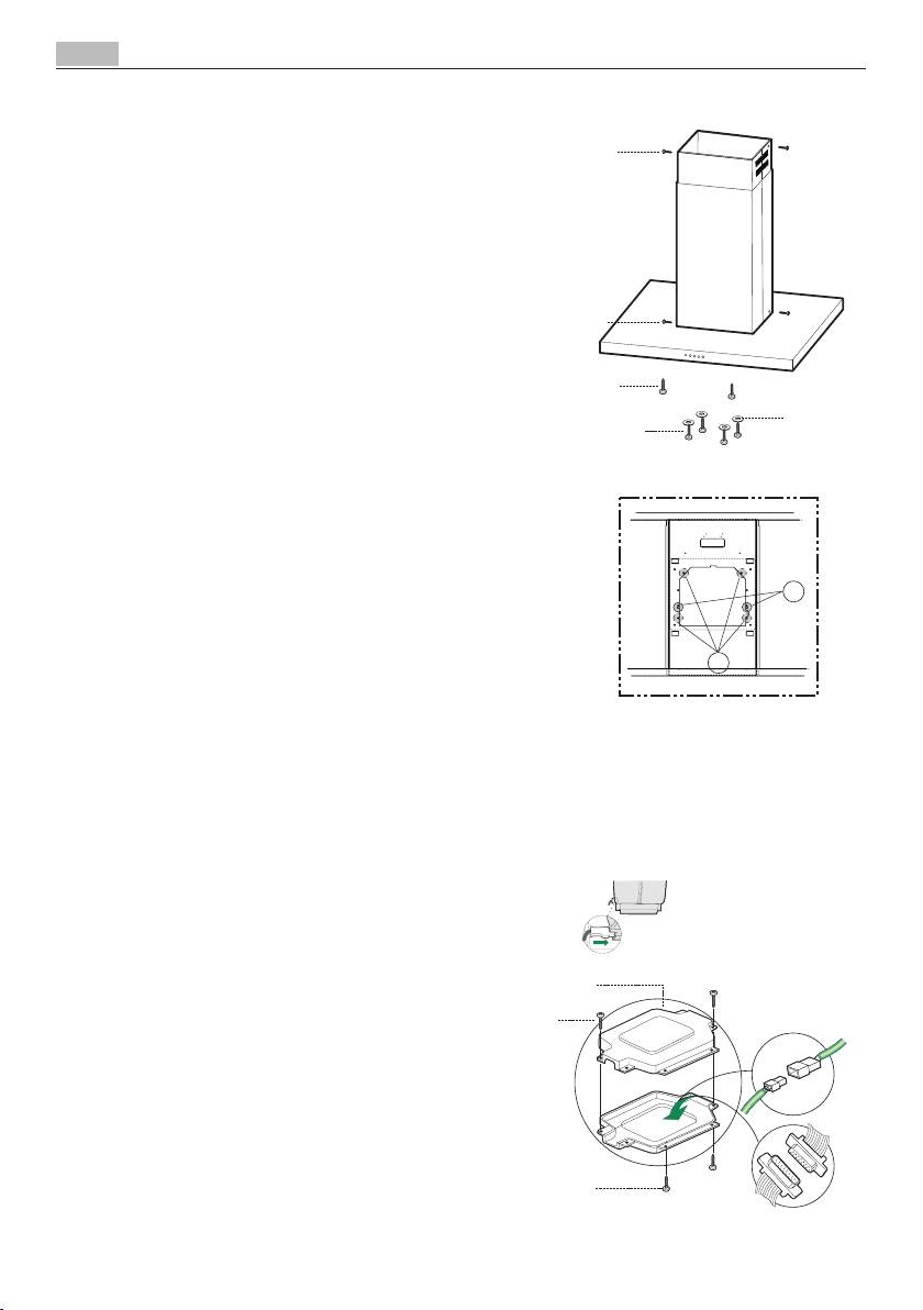
FLUE ASSEMBLY - MOUNTING THE HOOD BODY
• Position the upper chimney section and fix the
upper part to the frame using the 2 screws 12c
(2,9 x 6,5) provided.
• Similarly,positionthelowerchimneysectionand
fix the lower part to the frame using the 2 screws
12c (2,9 x 6,5) provided.
Before fixing the hood body to the frame:
• Screwthe2screws12f half way into the holes
provided in the sides of the bottom of the frame.
• Removethegreasefiltersfromthehoodcanopy.
• Removeanyactivatedcharcoalfilters.
• Liftthehoodcanopyandengagethescrews12f
in the slots (A) as far as they will go.
• Workingfrombelow,fixthehoodcanopytothe
frame (B), using the 4 screws 12q and 4 washers
22 provided, then tighten all the screws securely.
ELECTRICAL CONNECTION
• Connect the hood to the mainsthrougha two-
pole switch ha-ving a contact gap of at least 3
mm.
• Removethegreasefilters(seeparagraphMainte-
nance) being sure that the connector of the feed-
ing cable is correctly inserted in the socket placed
on the side of the fan.
• ConnectthecontrolconnectorCmd.
• ConnectthelightsconnectorLux.
• Placetheconnectorsinthejunctionbox24 and
close it using the 2 screws 12e (2,9 x 9,5) pro-
vided.
• Fixthejunctionboxtothehoodbodyusingthe2
screws 12c (2,9 x 6,5) provided.
• Fortherecirculationversion,fittheactivatedcar-
bon odour fil-ter.
• Replacethegreasefilters.
Table of contents
- PER RISULTATI PERFETTI Grazie per aver scelto di acquistare questo prodotto AEG. Lo abbiamo creato per fornirvi prestazioni impeccabili per molti anni, grazie a tecnologie innovative che vi semplificheranno la vita - funzioni che non troverete sui normali elettrodo- mestici. Vi invitiamo di dedicare qualche minuto alla lettura per sapere come trarre il massimo dal vostro elettrodomesti- co. ACCESSORI E PRODOTTI DI CONSUMO All'interno del webshop AEG troverete tutto ciò che vi ser- ve per fare in modo che i vostri elettrodomestici AEG siano sempre perfettamente puliti e funzionanti. Non mancano inoltre una vasta gamma di accessori studiati e realizzati conformemente agli elevati standard qualitativi che vi aspet- tate: pentole, scolaposate, portabottiglie e sacchi biancheria delicati...
- CONTENUTI
- CONSIGLI E SUGGERIMENTI
- CARATTERISTICHE
- INSTALLAZIONE
- USO
- MANUTENZIONE
- FOR PERFECT RESULTS Thank you for choosing this AEG product. We have created it to give you impeccable performance for many years, with innovative technologies that help make life simpler – featu- res you might not find on ordinary appliances. Please spend a few minutes reading to get the very best from it. ACCESSORIES AND CONSUMABLES In the AEG webshop, you’ll find everything you need to keep all your AEG appliances looking spotless and working per- fectly. Along with a wide range of accessories designed and built to the high quality standards you would expect, from specialist cookware to cutlery baskets, from bottle holders to delicate laundry bags…
- CONTENTS
- RECOMMENDATIONS AND SUGGESTIONS
- CHARACTERISTICS
- INSTALLATION
- USE
- MAINTENANCE
- FÜR PERFEKTE ERGEBNISSE Danke, dass Sie sich für dieses AEG Produkt entschieden haben.Wirhabenesgeschaffen,damitSievieleJahre von seiner ausgezeichneten Leistung und den innovativen Technologien, die Ihnen das Leben erleichtern, profitieren können. Es ist mit Funktionen ausgestattet, die in gewöhn- lichen Geräten nicht vorhanden sind. Nehmen Sie sich ein paar Minuten Zeit zum Lesen, um seine Vorzüge kennen zu lernen. ZUBEHÖR UND VERBRAUCHSMATERIALIEN Im AEG Webshop finden Sie alles, was Sie für ein makello- ses Aussehen und perfektes Funktionieren Ihrer AEG Geräte benötigen. Wir bieten auch ein umfangreiches Zubehörsor- timent, das Ihre höchsten Qualitätsansprüche erfüllt, vom Profi-Kochgeschirr bis zu Besteckkörben, von Flaschenhaltern bis hin zu Wäschebeuteln für empfindliche Wäsche...
- INHALT
- EMPFEHLUNGEN UND HINWEISE
- CHARAKTERISTIKEN
- MONTAGE
- BEDIENUNG
- WARTUNG
- ДЛЯ ОПТИМАЛЬНЫХ РЕЗУЛЬТАТОВ Благодарим Вас за выбор данного продукта AEG. Этот продукт будет безупречно служить Вам долгие годы – ведь мы создали его с помощью инновационных технологий, которые облегчат Вашу жизнь и создадут качества, которые Вы не найдете в привычных приборах. Потратьте немного времени на чтение, чтобы получить максимальную пользу от своей покупки. АКСЕССУАРЫ И РАСХОДНЫЕ МАТЕРИАЛЫ В интернет-магазине AEG Вы сможете найти все необходимое для того, чтобы все ваши приборы AEG сверкали чистотой и радовали Вас безотказной работой. Помимо этого, здесь Вы найдете широкий выбор аксессуаров, разработанных и изготовленных по самым высоким стандартам, какие только можно представить – от профессиональной кухонной посуды до лотков для хранения ножей, от держателей бутылок до мешков для деликатного белья…
- СОДЕРЖАНИЕ
-
-
- УСТАНОВКА
-
-
- Z MYŚLĄ O PERFEKCYJNYCH REZULTATACH Dziękujemy za wybór tego produktu AEG. Zaprojektowaliśmy go z myślą o wieloletniej bezawaryjnej pracy i wyposażyliśmy w innowacyjne technologie, które ułatwiają życie — nie wszyst- kie te funkcje można znaleźć w zwykłych urządzeniach. Pro- simy o poświęcenie kilku minut na lekturę w celu zapewnienia najlepszego wykorzystania urządzenia. AKCESORIA I MATERIAŁY EKSPLOATACYJNE W sklepie internetowym AEG można znaleźć wszystko co niezbędne do utrzymania urządzeń AEG w doskonałym stanie technicznym i wizualnym. Wśród szerokiej gamy akcesoriów, zaprojektowanych i wyprodukowanych zgodnie z wysokimi stan- dardami jakości, oferujemy specjalistyczne naczynia kuchenne, kosze na sztućce, półki na butelki oraz torby do delikatnego prania...
- ZAWARTOŚĆ
-
-
-
-
-
- ДЛЯ ВІДМІННОГО РЕЗУЛЬТАТУ Дякуємо, що обрали цей прилад AEG. Ми створили його для бездоганної роботи протягом багатьох років, за інноваційними технологіями, які допомагають робити життя простішим - ці властивості, які можна й не знайти в звичайних приладах. Будь ласка, приділіть декілька хвилин, аби прочитати, як отримати найкраще від цього приладу.. ПРИЛАДДЯ І ВИТРАТНІ МАТЕРІАЛИ В інтернет-магазині AEG ви знайдете усе необхідне, для того, аби усі ваші прилади AEG виглядали бездоганно і відмінно працювали. Також тут представлений широкий асортимент приладдя, розробленого та створеного за найвищими стандартами якості, - від спеціального посуду до кошиків для столових приборів, від тримачів для пляшок до мішків для прання делікатної білизни…
- РЕЗЮМЕ
- РЕКОМЕНДАЦІЇ ТА ПОРАДИ
- ОСОБЛИВОСТІ
- ВСТАНОВЛЕННЯ
- ВИКОРИСТАННЯ
- ОБСЛУГОВУВАННЯ
- MÜKEMMEL SONUÇLAR İÇİN Bu AEG ürününü seçtiğiniz için teşekkür ederiz. Bu ürünü, sıradan cihazlarda bulamayacağınız hayatı kolaylaştıran özel- likler ve yenilikçi teknolojiler kullanarak, size uzun yıllar üstün performans vermesi için tasarladık. Lütfen, cihazınızdan en iyi şekilde yararlanabilmek için birkaç dakikanızı ayırarak bu belgeyi okuyun. AKSESUARLAR VE SARF MALZEMELERİ AEG Internet mağazasında tüm AEG cihazlarınızı mükemmel durumda ve temiz kullanmanıza yardımcı olacak herşeyi bu- labilirsiniz. Beklentilerinize uygun yüksek kalite standartlarında tasarlanan ve üretilen çok çeşitli aksesuarların yanı sıra, uzmanların kullandığı pişirme kaplarından çatal-bıçak sepetleri- ne, şişe tutuculardan narin çamaşır torbalarına kadar herşey...
- IÇERIK
- TAVSIYELER VE ÖNERILER
- ÖZELLIKLER
- MONTAJ
- KULLANIM
- BAKIM
