Danfoss AVPQT (Gen. 2006): инструкция
Раздел: Климатическое Оборудование
Тип: Радиатор
Инструкция к Радиатору Danfoss AVPQT (Gen. 2006)
Instructions
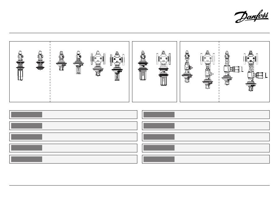
AVPQ, AVPQ-F, AVPQ 4, AVPQT – PN 16,25 / DN 15 – 50
ENGLISH
ČESKY
DEUTSCH
DANSK
NEDERLANDS
SLOVENŠČINA
POLSKI
ESPAÑOL
MAGYAR
РУСCКИЙ
73695040 DH-SMT/SI 01/ 2011
VI.DB.M2.8H
1
Page 2
www.danfoss.com
Seite 2
www.danfoss.de
Strana 2
www.danfoss.com
Blz. 2
www.danfoss.com
stran 20
www.danfoss.com
20. oldal
www.danfoss.hu
Page 20
www.danfoss.es
Strona 20
www.danfoss.pl
Стр. 20
www.danfoss.com
Differential pressure and flow controller
AVPQ, AVPQ-F, AVPQ 4, AVPQT
Differenzdruck- und Volumenstromregler
AVPQ, AVPQ-F, AVPQ 4, AVPQT
Regulátor diferenčního tlaku a průtoku
AVPQ, AVPQ-F, AVPQ 4, AVPQT
Drukverschil en debiet regelaar
AVPQ, AVPQ-F, AVPQ 4, AVPQT
Regulator diferenčnega tlaka in pretoka
AVPQ, AVPQ-F, AVPQ 4, AVPQT
Nyomáskülönbség és térfogatáram szabályozó
AVPQ, AVPQ-F, AVPQ 4, AVPQT
Regulador de presión diferencial y caudal
AVPQ, AVPQ-F, AVPQ 4, AVPQT
Regulator różnicy ciśnień i przepływu
AVPQ, AVPQ-F, AVPQ 4, AVPQT
Регулятор перепада давлений с автоматическим
ограничением расхода AVPQ, AVPQ-F, AVPQ 4, AVPQT
Differenstryk- og flowregulator
AVPQ, AVPQ-F, AVPQ 4, AVPQT
Side 2
www.danfoss.dk
AVPQ
AVPQ-F
AVPQ (PN 25)
(PN 16)
(PN 16)
DN 15 - 32
DN 15 - 32
DN 15 - 50
DN 15 - 50
DN 32 - 50
DN 32 - 50
∆
p = 0.1 - 0.5
∆
p = 0.2
∆
p = 0.2 - 1.0
∆
p = 0.3 - 2.0
∆
p = 0.2 - 1.0
∆
p = 0.3 - 2.0
∆
p = 0.2 - 1.0
∆
p = 0.3
AVPQ 4 (PN 25)
DN 15 - 50
DN 32 - 50
∆
p = 0.2 - 1.0
∆
p = 0.2 - 1.0
∆
p = 0.3 - 2.0
∆
p = 0.3 - 2.0
AVPQT (PN 25)
AVT/AVPQT (PN 25)
DN 15 - 25
DN 32 - 50
DN 15 - 25
DN 32 - 50
∆
p = 0.2 - 1.0
∆
p = 0.2 - 1.0
∆
p = 0.2 - 1.0
∆
p = 0.2 - 1.0
AVPQ, AVPQ-F, AVPQ 4, AVPQT – PN 16,25
2
DANSK ENGLISH DEUTSCH ČESKY
Contents
Safety Notes
3
Definition of applications 3
Assembly
4
- Admissible
Installation Positions
4
- Installation Location
and
Installation Scheme
4
- Valve Installation
5
- Mounting of
temperature actuator
6
- Impulse tube mounting 7
- Insulation
9
- Dimensions,
Weights
9
Start-up
11
- Filling the system, first
start-up
11
- Leak and pressure tests 12
- Putting out of
operation
13
- Settings
13
- Differential pressure
setting
13
- Flow rate setting
15
- Adjustment with flow
adjusting curves
16
- Flow Adjusting
Curves
18
- Adjustment with
Heat meter
19
- Temperature Setting
19
Inhalt
Sicherheitshinweise
3
Bestimmungsgemäße
Verwendung
3
Montage
4
- Zulässige Einbaulagen
4
- Einbauort,
Einbauschema
4
- Einbau Ventil
5
- Einbau Thermostat
6
- Montage Steuerleitung 7
- Isolierung
9
- Abmessungen,
Gewichte
9
Inbetriebnahme
11
- Füllung der Anlage,
Inbetriebnahme
11
- Dichtheits- und
Druckprüfung
12
- Außerbetriebnahme
13
- Einstellung Sollwerte
13
- Einstellung
Differenzdruck
13
- Einstellung
Volumenstrom
15
- Einstellung mit
Einstelldiagramm
16
- Einstelldiagramme
18
- Einstellung mit
Wärmezähler
19
Temperatureinstellung 19
Obsah
Bezpečnostní informace 3
Aplikační oblast
3
Montáž
4
- Přípustná instalační
poloha
4
- Umístění a schéma
instalace
4
- Instalace ventilu
5
- Montáž přímočinného
regulátoru teploty
6
- Montáž impulsního
potrubí
7
- Izolace
9
- Rozměry, Hmotnost
9
Zahájení provozu
11
- Plnění systému, první
spuštění
11
- Tlaková zkouška a
zkouška těsnosti
12
- Odstavování
13
- Nastavení
13
- Nastavení diferenčního
tlaku
13
- Nastavení průtoku
15
- Nastavení pomocí
diagramu nastavení
růtoku
16
- Diagramy nastavení
průtoku
18
- Nastavování pomocí
měřiče tepla
19
- Nastavení teploty
19
Inhouds opgave
Veiligheid
3
Toepassingen
3
Montage
4
- Toegestane
montage standen
4
- Installatie plaats en
Installatie schema
4
- Afsluiter installeren
5
- Montage van
temperatuurregelaar
6
- Impulsleiding monteren 7
- Isolatie
9
- Afmetingen,
Gewicht
9
Inbedrijfname
11
- Vullen van het systeem,
eerste inbedrijfstelling 11
- Lek en druk test
12
- Uit bedrijf nemen
13
- Instellingen
13
- Drukverschil instelling 13
- Debiet instelling
15
- Instelling met debiet
grafieken
16
- Debiet instel-
grafieken
18
- Instelling met
warmtemeter
19
- Temperatuurinstelling 19
NEDERLANDS
Indholdsfortegnelse
Sikkerhedsnoter
3
Anvendelse
3
Montering
4
- Tilladelige positioner
4
- Indbygning
4
- Ventilinstallation
5
- Montering af
temperaturaktuator
6
- Montering af
impulsledning
7
- Isolering
9
- Mål, vægt
9
Opstart
11
- Påfyldning af systemet,
første opstart
11
- Lækage- og
trykprøvning
12
- Stop af anlæg
13
- Indstilling af
sætpunkter
13
- Differenstrykindstilling 13
- Indstilling af flowet
15
- Justering vha.
flow kurver
16
- Flow kurver
18
- Justering vha
varmemåler
19
- Indstilling af
temperatur
19
AVPQ, AVPQ-F, AVPQ 4, AVPQT – PN 16,25
3
DANSK ENGLISH DEUTSCH ČESKY NEDERLANDS
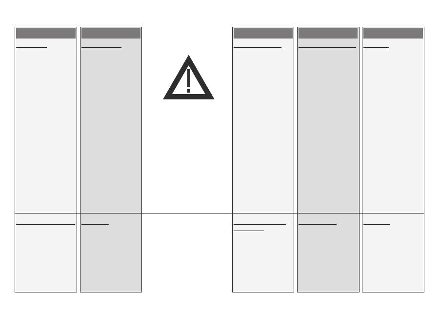
Safety Notes
Prior to assembly and
commisioning to avoid injury
of persons and damages of
the devices, it is absolutely
necessary to carefully read
and observe these instruc-
tions.
Necessary assembly, start-
up, and maintenance work
must be performed only
by qualified, trained and
authorized personnel.
Prior to assembly and
maintenance work on the
controller, the system must be:
- depressurized,
- cooled down,
- emptied and
- cleaned.
Please comply with the
instructions of the system
manufacturer or system
operator.
Definition of Application
The controller is used for
differential pressure and flow
(and temperature at AVPQT)
control of water and water
glycol mixtures for heating,
district heating and cooling
systems.
The technical parameters on
the product labels determine
the use.
Sicherheitshinweise
Um Verletzungen an
Personen und Schäden am
Gerät zu vermeiden, ist diese
Anleitung vor der Montage
unbedingt zu beachten.
Montage, Inbetriebnahme
und Wartungsarbeiten
dürfen nur von sachkundigen
und autorisierten Personen
durchgeführt werden.
Vor Montage und
Wartungsarbeiten am Regler
die Anlage:
- drucklos machen,
- abkühlen,
- entleeren und
- reinigen.
Die Vorgaben des
Anlagenherstellers und
Anlagenbetreibers sind zu
beachten.
Bestimmungsgemäße
Verwendung
Der Regler regelt den
Differenzdruck- und begrenzt
den Volumenstrom von
Wasser und Wasser-Glykol-
Gemischen in Heizungs-,
Fernheizungs- und
Kühlungsanlagen.
Die technischen Daten auf
den Typenschildern sind für
den Einsatz maßgebend.
Bezpečnostní informace
Z důvodu maximálního
snížení možnosti poranění
osob nebo vzniku škod na
majetku je bezpodmínečně
nutné se před vlastní montáží
a uvedením regulátoru do
provozu pečlivě seznámit
se všemi bezpečnostními
informaci zde uvedenými.
Nezbytné montážní práce,
kroky při uvádění do provozu
a opravy mohou provádět
pouze kvalifikovaní, proškolení
pracovníci, kteří byly pro tuto
činnost určeni.
Před montáží nebo před
případnou opravou nebo
servisem regulátoru je nutné,
aby regulovaný systém
splňoval následující podmínky:
- nebyl pod tlakem
- byl dostatečně ochlazen
- vyprázdněn a
- vyčištěn.
Potupujte podle návodu
výrobce systému nebo jeho
provozovatele.
Aplikační oblast
Regulátor je určen pro
regulaci diferenčního tlaku
a průtoku vody a směsi vody
s glykolem v systémech
vytápění, v systémech
centralizovaného zásobování
teplem a v chladících
systémech.
Technické parametry
uvedené na typovém štítku
výrobku určuji jeho použití.
Veiligheid
Om verwondingen aan
personen en schade aan de
apparatuur te voorkomen is
het absoluut noodzakelijk om
deze instructies zorgvuldig te
lezen en te bestuderen.
Noodzakelijke (de)montage,
inbedrijfstelling en
onderhoud dient alleen
door deskundig, getraind
en bevoegd personeel te
worden uitgevoerd.
Voorafgaand aan montage- of
onderhoudswerkzaamheden
moet het systeem worden:
- afgesloten,
- afgekoeld,
- afgetapt en
- gereinigd.
Volg altijd de instructies
van de installatiebouwer- of
beheerder op.
Toepassing
De regelaar wordt gebruikt
voor het constant houden
van het drukverschil en het
begrenzen van het debiet in
installaties voor verwarming,
stadsverwarming en koeling,
gevuld met water of water-
glycol mengsels.
De technische gegevens op
het type-plaatje bepalen de
toepassings mogelijkheden.
Sikkerhedsnoter
Disse instruktioner SKAL
læses omhyggeligt forud
for montering og indkøring
samt respekteres for at
undgå skader på personer
og udstyr. Nødvendigt
monterings-, opstart- og
vedligeholdelsesarbejde må
kun udføres af faglært og
autoriseret personale.
Forud for monterings- og
vedligeholdelsesarbejde på
regulatoren skal systemet
være:
- trykløst,
- nedkølet,
- tømt og
- rengjort.
Systemproducentens eller
-operatørens instruktioner
skal overholdes.
Anvendelse
Regulatoren anvendes
til differenstryk- og
flowstyring af vand og vand-
glycolblandinger til varme-,
fjernvarme- og kølesystemer.
De tekniske parametre
på produktetiketterne
fastlægger anvendelsen.
AVPQ, AVPQ-F, AVPQ 4, AVPQT – PN 16,25
4
DANSK ENGLISH DEUTSCH ČESKY NEDERLANDS
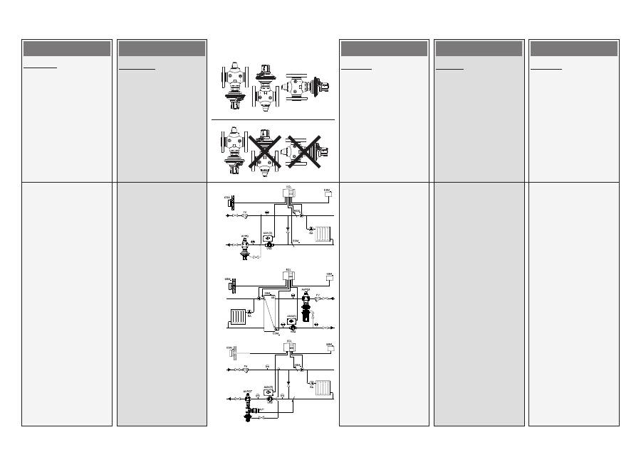
Assembly
Admissible Installation
Positions
Medium temperatures
up to 100 °C:
- Can be installed in any
position.
Medium temperatures
> 100 °C:
- Installation permitted only
in horizontal pipelines
with the actuator oriented
downwards.
Installation Location and
Installation Scheme
AVPQ(-F)
return mounting
AVPQ 4
flow mounting
AVPQT
return mounting
Montage
Zulässige Einbaulagen
Mediumstemperaturen bis
100 °C:
- Einbaulage beliebig.
Mediumstemperaturen
> 100 °C:
- Einbau nur in waagerechte
Rohrleitung mit nach
unten hängendem Antrieb
zulässig..
Einbauort, Einbauschema
ACHTUNG!
Der Regler AVPQ kann nur in
den Rücklauf, AVPQ 4 nur in
den Vorlauf eingebaut werden.
AVPQ(-F)
Einbau im Rücklauf
AVPQ 4
Einbau im Vorlauf
AVPQT
Einbau im Rücklauf
Montáž
Přípustná instalační poloha
Teplota média do 100°C:
- Regulátor lze instalovat v
jakékoliv poloze.
Teplota média vyšší než 100°C:
- Regulátor je možné
instalovat pouze na
vodorovné části potrubí,
kdy pohon regulátoru
směřuje dolů.
Umístění a schéma
instalace
AVPQ(-F)
Montáž na vratnou větev
AVPQ 4
Montáž na přívodní větev
AVPQT
Montáž na vratnou větev
Montage
Toegestane montage posities
Mediumtemperatuur tot 100 °C:
- Mag in alle standen
gemonteerd worden.
Mediumtemperatuur
> 100 °C:
- Montage alleen
toegestaan in horizontale
leidingen met het
regelelement omlaag.
Plaats in de installatie en
installatieschema
AVPQ(-F)
montage in retour
AVPQ 4
montage in aanvoer
AVPQT
montage in retour
Montering
Tilladelige positioner
Medietemperaturer op til
100 °C:
- Kan monteres i alle
positioner.
Medietemperaturer > 100 °C:
- Må kun installeres i
vandrette rørledninger
og med aktuatoren
hængende nedad.
Indbygning
AVPQ(-F)
montering i returledning
AVPQ 4
montering i flowledning
AVPQT
montering i returledning
Оглавление
- DANSK ENGLISH DEUTSCH ČESKY
- DANSK ENGLISH DEUTSCH ČESKY NEDERLANDS
- DANSK ENGLISH DEUTSCH ČESKY NEDERLANDS
- DANSK ENGLISH DEUTSCH ČESKY NEDERLANDS
- DANSK ENGLISH DEUTSCH ČESKY NEDERLANDS
- DANSK ENGLISH DEUTSCH ČESKY NEDERLANDS
- DANSK ENGLISH DEUTSCH ČESKY NEDERLANDS
- DANSK ENGLISH DEUTSCH ČESKY NEDERLANDS
- DANSK ENGLISH DEUTSCH ČESKY NEDERLANDS
- DANSK ENGLISH DEUTSCH ČESKY NEDERLANDS
- DANSK ENGLISH DEUTSCH ČESKY NEDERLANDS
- DANSK ENGLISH DEUTSCH ČESKY NEDERLANDS
- DANSK ENGLISH DEUTSCH ČESKY NEDERLANDS
- DANSK ENGLISH DEUTSCH ČESKY NEDERLANDS
- SLOVENSKO MAGYAR
- SLOVENSKO MAGYAR POLSKI
- SLOVENSKO MAGYAR POLSKI
- SLOVENSKO
- MAGYAR SLOVENSKO ESPAÑOL POLSKI РУССКИЙ
- SLOVENSKO MAGYAR POLSKI
- SLOVENSKO MAGYAR POLSKI
- SLOVENSKO MAGYAR POLSKI
- SLOVENSKO MAGYAR POLSKI
- SLOVENSKO MAGYAR POLSKI РУССКИЙ ESPAÑOL
- SLOVENSKO MAGYAR POLSKI
- SLOVENSKO MAGYAR POLSKI
- SLOVENSKO MAGYAR POLSKI
- SLOVENSKO MAGYAR POLSKI
- SLOVENSKO MAGYAR POLSKI
- SLOVENSKO MAGYAR POLSKI
