Bowers & Wilkins CWM3: инструкция
Раздел: Бытовая, кухонная техника, электроника и оборудование
Тип: Микрофон
Инструкция к Микрофону Bowers & Wilkins CWM3

CWM3

2
E
N
G
L
IS
H
www.bowers-wilkins.com Welcome to Bowers & Wilkins and the CWM3 Series Thank you for choosing Bowers & Wilkins. When John Bowers first established our company he did so in the belief that imaginative design, innovative engineering and advanced technology were keys that could unlock the enjoyment of audio in the home. His belief is one that we continue to share and it inspires every product we design.
ENGLISH
Contents
ENGLISH
2
1. Unpacking 3 2. CWM3 Series Basics 3 3. Positioning CWM3 Series Speakers 3 4. Installing CWM3 Series Speakers 4 5. Using a Pre-mount Kit 5 6. Using a Back-box Kit 6
3
E
N
G
L
IS
H
1. Unpacking
CWM3 Series in-wall speakers are designed to offer
easy installation and high quality audio reproduction
for discrete custom install applications. They are
particularly suitable for use in humid environments
such as swimming pools. This manual describes
the installation of CWM3 Series speakers within
conventional stud and sheetrock (joist and
plasterboard) walls. It begins by listing the contents
of the carton:
1. Two CWM3 Series speakers
2. Two CWM3 Series speaker grilles
3. Two aperture templates
4. Two paint masks
5. Quick Start Guide
6. Warranty information
2. CWM3 Series Basics
CWM3 Series in-wall speakers comprise a baffle
carrying the speaker drivers, crossover circuit and
connectors, and a magnetically secured grille. The
baffle is secured in the wall aperture by dog-clamps
that swing outwards and tighten.
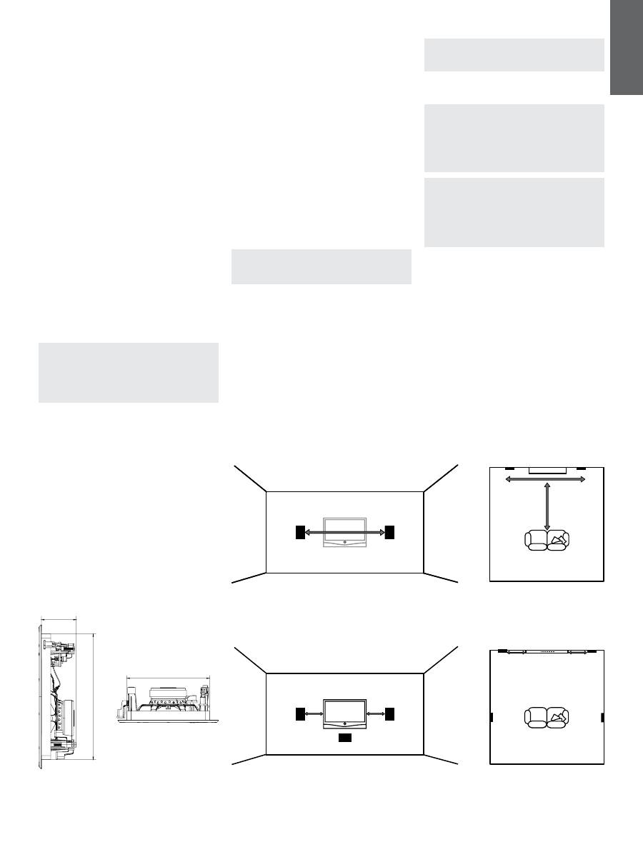
CWM3 Series in-wall speakers require wall aperture
and minimum depth clearance as follows:
Model
CWM362
Aperture Height
275mm (10.9 in)
Aperture Width
181mm (7.2 in)
Minimum Depth Clearance
76mm (3 in)
Note: If CWM3 Series speakers are to be
installed in “new build” projects, pre-mount kits
and back boxes are available. Use of pre-mount
kits is described in Section 5. Use of back-boxes
is described in the separate CI300 Back-box
Installation document.
Before installing CWM3 Series speakers you should
ensure that the wall locations chosen are free of
obstructions such as pipe work, ducting or wiring
that will interfere with the installation. In existing
dry-wall construction, use a stud-finding tool to help
you map the wall construction and a pipe detector to
scan the proposed installation locations.
3. Positioning CWM3 Series Speakers
The appropriate position for CWM3 Series speakers
within the listening environment will depend on their
specific application:
General Background Audio Applications:
For applications where single CWM3 Series speakers
are required to operate independently to provide
background audio, they can be located substantially
as installation convenience and architecture dictate.
The only acoustic constraint to bear in mind is that
corner locations will result in significantly emphasised
low frequencies and should be avoided.
Stereo Audio Applications:
For applications where a pair of CWM3 Series
speakers is to be used for conventional stereo
reproduction, they should be located between 3m
(10 ft) and 5m (16.5ft) apart and a similar distance
in front of the listening area. Try to avoid corner
locations for the speakers and to ensure that
acoustic environment around each speaker is similar.
Note: Different acoustic environments might
be, for example, a bare wall and a heavily
curtained window.
Multi-channel Audio Applications
For applications where multiple CWM3 Series
speakers are to be used for multi-channel audio
visual systems, the left and right front speakers
should be located either side of the screen
approximately 0.5m (20 in) away. The centre channel
speaker should be located either directly above or
below the screen or, in the case of an acoustically
transparent screen, directly behind. Surround
channel CWM3 Series speakers should be located
just behind and either side of the listening position.
Try to avoid corner locations for any of the speakers
and to ensure that the acoustic environment around
each front and surround speaker is similar.
Note: Different acoustic environments might
be, for example, a bare wall and a heavily
curtained window.
Diagram 2 illustrates the general speaker location
guidelines.
Note: The nature of the installation of in-wall
speakers means that it is sometimes impractical
to locate them in the acoustically ideal positions.
In these cases they should be located as close
as is practical to the ideal positions. Your local
Bowers & Wilkins retailer will be able to offer
advice if required.
Note: CWM3 Series drive units create
stray magnetic fields. We recommend that
magnetically sensitive items such as CRT
screens and magnetic cards for example, are
kept at least 0.5m (20 in) from the speaker.
LCD and plasma screens are not affected by
magnetic fields.
0.5m (20 in) 0.5m (20 in) 0.5m (20 in) 0.5m (20 in) 3m (10 ft) - 5m (16.5ft) 3m (10 ft) - 5m (16.5ft) 3m (10 ft) - 5m (16.5ft) Diagram 2 Positioning Diagram 1 Aperture and height clearance
3m (10 ft) - 5m (16.5 ft)
0.5m (20in)
0.5m (20in)
0.5m (20in)
0.5m (20in)
3m (10 ft) -
5m (16.5 ft)
181mm (7.2in)
27
5m
m
(1
0.
9i
n)
76mm (3in)
Stereo Audio Applications
Multi-channel Audio Applications
4
E
N
G
L
IS
H
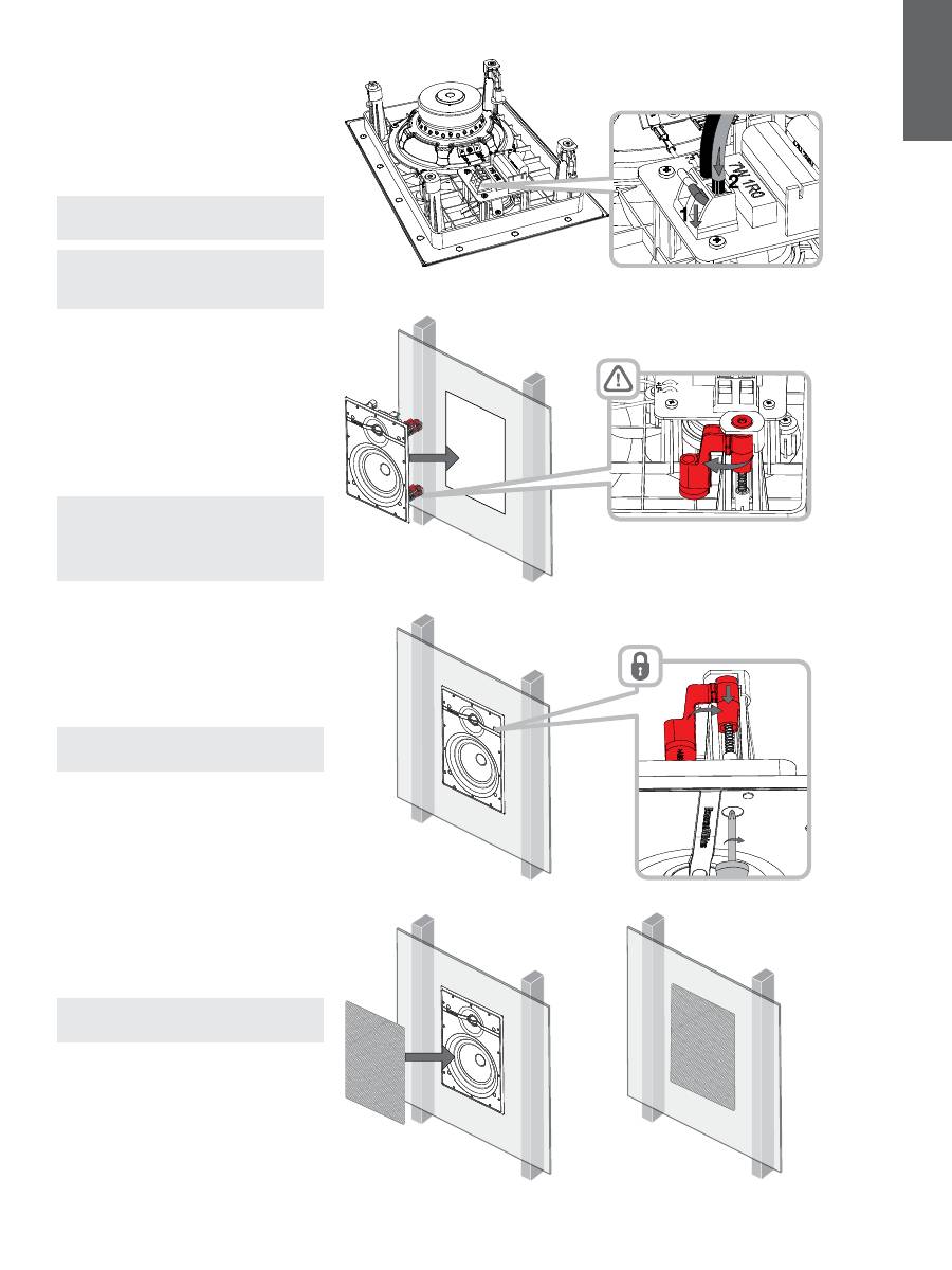
Diagram 3 Cable connection 4. Installing CWM3 Series Speakers
To install a CWM3 Series speaker, proceed as
described in the following paragraphs:
4.1
Using the supplied aperture template, mark a
cut line on the wall. Check the cut line defines the
correct aperture dimensions. Cut along the line with
an appropriate tool to create a rectangular aperture
in the wall.
Note: Ensure that there is enough free space
internally adjacent to the aperture for the dog
clamps.
Note: To reduce the possibility of the wall buzzing
or rattling, adhesive mastic can be applied
between the studs and sheetrock in the vicinity
of the speaker aperture.
4.2
If speaker cable is already present in the wall,
feed the cable through the aperture. If speaker
cables are not already installed, this should be done
at this stage. It is likely that you will need to gain
access through the floor above to route the cables
down through the wall space.
Leave enough spare cable through the aperture to
ease connection to the speaker, but not so much
that it is likely to buzz or rattle when pushed back
into the wall space. Approximately 1.0m (3 ft) is
appropriate.
Note: Always use high quality, low resistance
speaker cable. Low resistance is especially
important if the length of cable from amplifier
to speaker exceeds 5m. Your local Bowers &
Wilkins retailer will be able to offer advice on
speaker cable selection if required.
4.3
Now connect the speaker cable to the spring
terminals on the crossover board. Ensure that the
speaker connection polarity is correct: the cable
connected to the positive terminal on the amplifier
should be connected to the red spring terminal
on the speaker. Similarly, the cable connected
to the negative terminal on the amplifier should
be connected to the black spring terminal on the
speaker. Diagram 3 illustrates cable connection.
Note: If an amplifier is already connected to the
cable it should be switched off while connections
are being made to the back box.
4.4
With the speaker connected to the cable, it
can be inserted into the wall aperture. Ensure that
the four dog clamps are rotated inwards so that
they can pass through the aperture, and then hold
the speaker flange flush to the wall. Take care that
the connection cable does not become trapped
anywhere.
To secure the speaker use a Phillips screwdriver
inserted through the dog-clamp access holes in the
front of the speaker. Take great care not to damage
the speaker drive units with the screwdriver. Engage
the screwdriver with each dog-clamp screw in turn
and tighten them. Diagram 4 illustrates inserting and
securing the speaker.
Note: If the wall is to be painted after the
speakers have been installed, the supplied paint
mask should be used.
4.5
The grille can now be fitted. The grille is held in
place magnetically so simply needs to be aligned
with the groove in the frame flange where it will click
into place. Diagram 5 illustrates fitting the grille.
The CWM3 Series speaker is now installed and
ready for use.
Diagram 4 Secure the speaker Diagram 5 Fitting the grille
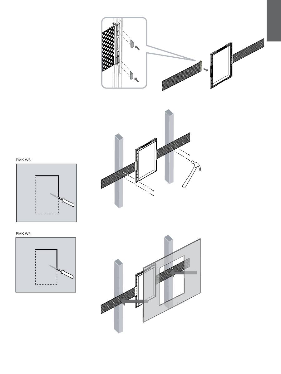
5. Using a Pre-mount Kit
Custom install pre-mount kits enable the locations of
in-ceiling and in-wall speakers to be defined before
the sheetrock (plasterboard) is fitted to the studs
(joists). Routing and cutting of speaker cable is also
made easier using pre-mount kits. A pre-mount kit
(PMK) comprises a plastic moulding that defines
the aperture size of the specific speaker model, two
perforated metal straps and four plastic clips.
To use a PMK, first attach one strap to each side
of the moulding using the plastic clips. The PMK
assembly can now be attached to the studwork
by nailing the metal straps to the studs so that
the plastic moulding is located at the appropriate
position.
When the sheetrock (plasterboard) is subsequently
fitted (marked on the outside to denote the position
of the pre-mount kit) the PMK plastic moulding
serves as an internal cut guide that significantly
eases cutting the speaker aperture.
Diagrams 6-9 illustrate PMK installation.
5
E
N
G
L
IS
H
Diagram 6 PMK strap attachment Diagram 7 PMK stud (joist) installation Diagram 9 Sheetrock (plasterboard) installation Diagram 8 PMK cutout dimensions 189mm (7.4in) 159mm (6.3in) 23 4m m (9 .2 in ) 28 5m m (1 1. 2i n)
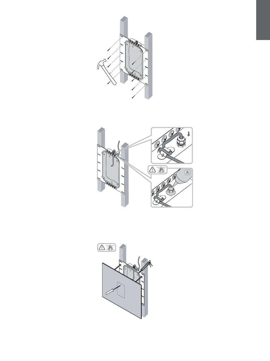
6. Using a Back-box Kit
Custom install back-box kits comprise a fire-proof
box that can be fitted behind in-wall or ceiling
speakers before the sheetrock (plasterboard) is fitted
to the studs (joists). As well as enabling compliance
with fire regulations, back-boxes also help optimise
speaker performance by providing a defined acoustic
loading volume. A minimum clearance depth of
90mm from the outer stud (joist) plane to any rear
obstruction is required to fit a back-box.
Back-boxes incorporate holed side flanges that are
intended to be nailed to adjoining studs (joists). All
the nail holes should be used to help minimise the
risk of the flange vibrating against the stud (joist)
when the speaker is in use.
Speaker cable is bought into back-boxes via sealing
glands. Once the cable has been brought through
the gland, and the gland tightened, fire-retardant
sealing mastic should be used to seal the assembly.
Ensure that a generous length of cable is available
in the back-box before the gland is sealed. A cable
clamp adjacent to the gland provides cable strain
relief.
When the sheetrock (plasterboard) is fitted over the
back box a generous bead of fire-retardant sealing
mastic should be applied to the back box flanges
in order to seal the assembly and minimise the
possibility of vibration when the speaker is in use.
Diagrams 10-12 illustrate back-box installation.
6
E
N
G
L
IS
H
Diagram 10 Back-box stud (joists) installation Diagram 11 Cable installation Diagram 12 Sheetrock (plasterboard) installation
Оглавление
- www.bowers-wilkins.com Welcome to Bowers & Wilkins and the CWM3 SeriesThank you for choosing Bowers & Wilkins. When John Bowers first established our company he did so in the belief that imaginative design, innovative engineering and advanced technology were keys that could unlock the enjoyment of audio in the home. His belief is one that we continue to share and it inspires every product we design.
- www.bowers-wilkins.com Bienvenue dans le monde Bowers et Wilkins et à la CWM3 SeriesNous vous remercions d’avoir choisi Bowers & Wilkins. Lorsque John Bowers a créé sa société, il savait déjà qu’un design imaginatif, une conception innovante et une technologie avancée seraient les clés du plaisir de l’écoute de la musique chez soi. C’est cette philosophie qui, aujourd’hui, continue de nous inspirer pour la conception de chaque nouvel appareil.
- www.bowers-wilkins.com Willkommen bei Bowers & Wilkins und der CWM3-SerieDer Firmengründer John Bowers war der Meinung, dass ein wunderschönes Design, eine innovative Konstruktion und ausgeklügelte Technologien die Schlüssel zu Audio-Entertainment der Extraklasse in Ihrem Zuhause sind. Wir teilen seine Meinung und jedes von uns entwickelte Produkt basiert darauf.
- www.bowers-wilkins.com Bem-vindo à Bowers & Wilkins e à Série CWM3Obrigado por escolher Bowers & Wilkins. Quando John Bowers fundou a nossa empresa, fê-lo na convicção de que um design criativo, um projecto inovador e uma tecnologia avançada seriam as chaves que podiam desbloquear a apreciação do som em ambiente doméstico. A sua visão é a que continuamos a partilhar e que inspira cada um dos produtos que produzimos.
- www.bowers-wilkins.com Benvenuto e grazie per aver scelto i diffusori Bowers & Wilkins della Serie CWM3.Quando John Bowers fondò la nostra società, era convinto che design attraente, capacità d’innovare e tecnologie all’avanguardia fossero i fattori vincenti per la riproduzione audio domestica. Le sue idee sono ancor oggi condivise da noi tutti e fonte d’ispirazione per ogni nuovo modello che progettiamo.
- www.bowers-wilkins.com Welkom bij Bowers & Wilkins en de CWM3 SerieDank u voor het kiezen van Bowers & Wilkins. Toen John Bowers het bedrijf oprichtte, was hij ervan overtuigd dat een fantasievol ontwerp, innovatieve techniek en moderne technologie de sleutels vormden tot muziekbeleving thuis. Het is deze overtuiging waar we nog steeds van uitgaan en die de inspiratie vormt voor elk product dat we ontwerpen.
- www.bowers-wilkins.com Добро пожаловать и благодарим вас за приобретение акустики Серии CWM3 компании Bowers & Wilkins.Наш основатель, Джон Бауэрс, верил в то, что творческий подход в проектировании, новаторская конструкция и передовые технологии смогут открыть людям путь к подлинному звучанию в доме. Мы продолжаем разделять его веру, и она вдохновляет нас при проектировании всех новых продуктов.
- www.bowers-wilkins.com Vítejte u Bowers and Wilkins s reprosoustavami řady CWM3Děkujeme vám, že jste se rozhodli pro Bowers & Wilkins. Když John Bowers zakládal svou firmu, věřil že zajímavý design, inovativní výzkum a pokročilé technologie jsou klíčem otevírajícím dveře domácí zábavě. My v jeho myšlenkách pokračujeme a při vývoji každého produktu se jimi inspirujeme.
- www.bowers-wilkins.com Üdvözli Önt a Bowers & Wilkins és a CWM3 sorozatKöszönjük, hogy a Bowers & Wilkins-t választotta. Amikor John Bowers megalapította a cégünket, abban a hitben tette, hogy a kreatív dizájn, az innovatív tervezés és a fejlett technológia a kulcsai az otthoni zenehallgatás élvezetének. Az Ő hite az egyik ok, amiért mi folytatjuk és inspirál minket minden termékünk tervezésénél.
- www.bowers-wilkins.com Witamy w Bowers & Wilkins i przedstawiamy produkty serii CWM3Dziękujemy za wybór produktu firmy Bowers & Wilkins. John Bowers założył swoją firmę, ponieważ uważał, iż ciekawy wygląd, innowacyjna konstrukcja i zaawansowana technologia są kluczami do rozkoszowania się dźwiękiem w domowym zaciszu. Ta właśnie wizja towarzyszy nam i inspiruje każdy produkt, który tworzymy.
- www.bowers-wilkins.com 欢迎来到Bowers & Wilkins及CWM3系列感谢阁下购买Bowers & Wilkins产品。当我们的创办人John Bowers先生最初创立本公司的时候,他坚信充满想象的设计、创新的工程和先进的技术是开启家庭音响娱乐大门的重要元素。我们依然坚持着他的信念,并赋予我们所有产品设计灵感。
- www.bowers-wilkins.com Bowers & WilkinsとCWM3シリーズのご紹介Bowers & Wilkinsをお選びいただきありがとうございます。John Bowersは、Bowers & Wilkinsを設立した当初、創意に富んだデザインと革新的な工業技術、そして先進技術が、家庭でオーディオを存分に楽しむ鍵であると信じていました。その信念は今に引き継がれており、Bowers & Wilkinsが設計するあらゆる製品に命を吹き込んでいます。
