Bowers & Wilkins Signature 8NT: инструкция
Раздел: Бытовая, кухонная техника, электроника и оборудование
Тип: Микрофон
Инструкция к Микрофону Bowers & Wilkins Signature 8NT
Installation Instructions
Contents
English
1
Français
4
Deutsch
8
Español
12
Italiano
16
Nederlands
20
Русский
24
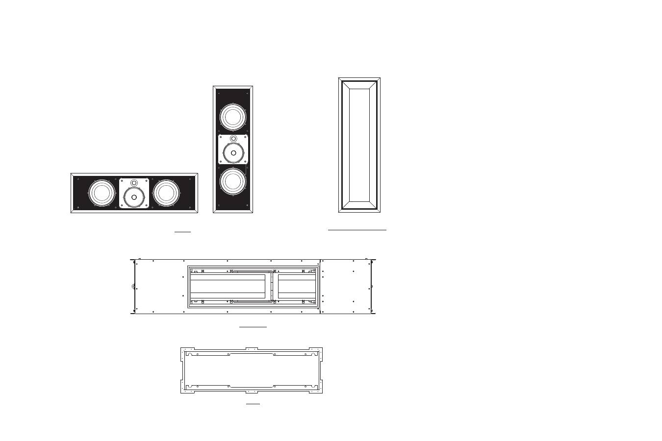
Cut-off diagrams
Wall frame and grille
PMK
Back box
Baffle

English
INTRODUCTION
Description
The Signature 8NT is a 3-way in-wall speaker
capable of true audiophile performance.
The total design is divided into four separate
modules:
1. Wall frame and grille
2. Baffle with drive units and crossover
3. PMK (Pre/post Mount Kit)
4. Back box
Separately packing each module enables parts
to be stored safely off site until they are needed.
The first two modules are required for all
installations and so are delivered together in a
master carton. See below in this section to find
out whether you need either the PMK or the
back box for your particular application. You will
need one of them, but not both.
The speaker may be bi-wired or bi-amplified if
desired. On delivery, the two pairs of input
terminals are shorted together for single wiring by
two looped link wires on the crossover board. To
bi-wire or bi-amplify, snip these link wires at the
top of the loop. This will allow enough length for
reconnection later if desired.
Do not begin the work until you have thoroughly
read this guide.
To get the best from the speaker, it is important
that it is installed in a proper manner. We suggest
you familiarise yourself fully with these
instructions before starting any work. If there is
any point you do not understand, help and
advice is available from the appointed B&W
distributor/importer in your country.
Installation options
Warning;
The speaker drive units create stray magnetic
fields, which may affect televisions containing
conventional cathode ray picture tubes. Keep the
speaker at least 50cm (20 in) clear of such
devices. Some particularly sensitive televisions
may require further spacing.
The Signature 8NT can be installed in drywall or
solid construction in either vertical or horizontal
orientation. With existing drywall construction,
the speaker can readily be retrofitted in the
vertical orientation. However, horizontal
orientation requires cutting into vertical wall
studs, so is a major job, more akin to new
construction than normal retrofit.
The wall frame and grille
The wall frame is installed after final plastering,
but before decorating. The grille mesh and frame
may be painted as desired before the baffle and
drivers are fitted.
The baffle
The baffle contains all the working parts of the
system. Having it separate from the frame makes
it easier to fit the frame and avoids possible
damage to the drivers during decorating.
The back box
In drywall construction, the back box provides
extra sound insulation between adjacent rooms
and a safety barrier to the spread of fire between
the wall cavity and the room. If you are working
with solid walls, the back box gives a defined
working volume that extends beyond the
immediate area of the speaker itself. Any smaller
volume and the speaker will have a restricted
bass performance. For extra flexibility in
installation, for example keeping clear of other
objects in the wall, the speaker may be
positioned either in the centre of the back box, or
to one end. (Figure 16 )
The PMK
The PMK is used in drywall construction
whenever the back box is not required, whether
new construction or retrofit.
PLANNING THE SPEAKER POSITION
Overview
Consider carefully where the speakers are to be
placed in the room according to the application.
The following are guidelines but, as with any
custom installation, specific on-site conditions
may require adaptation. In particular, the position
of wall studs in drywall construction may
necessitate adjustment of the recommended
speaker position.
The speaker may be installed in either vertical or
horizontal orientation, the latter normally used for
centre channel applications to allow positioning
above or beneath the screen.
In order to maintain optimum horizontal
dispersion through the upper crossover region
and cover a spread of listeners, the centre
portion of the baffle containing the midrange and
tweeter should be rotated by 90º so that the
drivers are positioned one above the other.
The summing axis of the midrange and tweeter is
deliberately tilted 5º towards the midrange driver
and this, together with the ability to rotate of the
centre portion of the baffle, permits greater
freedom when planning the vertical position of
the speakers. If the speaker is to be mounted
with its centre above ear height, turn the sub-
baffle so that the tweeter is above the midrange.
If it is to be mounted below ear height, have the
tweeter below the midrange. Try to keep the
centre within 10º of ear height for best results.
Beyond 10º, a response dip at crossover will
begin to develop, which will make the sound
seem more recessed. Consider 15º the
maximum to allow. (Figure 1)
In horizontal orientation, the speaker will cross
normally spaced vertical drywall studs, so special
stud construction will be required to give the
necessary clearance, even if not using the back
box.
2-channel audio
Aim to have the speakers and the front centre
listener approximately at the corners of an
equilateral triangle. The listening distance will
then determine the speaker separation. If you are
restricted, err on the side of having the speakers
closer together to avoid the 'hole in the middle'
effect. (Figure 2)
The height of the speakers should ideally be
such that the centre of the baffle is within 10º of
ear height.
Multi-channel left/right front
The angle between the speakers at the listener is
normally less than for 2-channel audio. Normally
this means the speakers are within 0.5m (20 in)
of the side of the screen.
The height should be chosen so that the centre
of the baffle is as close to screen centre height
as possible, while keeping within 10º of ear
height.
Multi-channel centre front
If using an acoustically transparent projection
screen, position the speaker as close to screen
centre as possible, while keeping within 10º of
ear height. Use vertical orientation.
In all other cases, orient the speaker horizontally
and place it either immediately above or below
the screen.
Multi-channel surround
Place the speakers with the centre of the baffle
around 60cm (2 ft) above ear height to give a
more diffuse sound than from the front speakers.
For 5.1 channel systems, the two surround
speakers should be positioned an angle of
approximately 120º round from front centre.
(Figure 3) For 6.1 EX systems, the two side
speakers should be more forward than this,
almost in line with the listeners. One speaker
should be placed on the rear wall directly in line
with the centre of the listening area. Alternatively
two rear speakers may be used side by side, one
either side of a stud in drywall construction.
(Figure 4) For 7.1 systems, the two rear speakers
should be further apart. A good guideline is for
them to have an angular spread of about 40º to
the listeners. (Figure 5)
1
CHECK THE CONTENTS
INSTALLATION PROCEDURES
Stage 1 – cutting the sheetrock
(plasterboard)
Simple retrofitting is only possible with vertical
orientation. For horizontal orientation, follow the
instructions for new construction.
Use a stud-finding tool to find the position of the
wall studs. Preferably choose a cavity that has no
other services running through it in order to avoid
the likelihood of rattles. There should be a
minimum of 120cm (4 ft) between any cross
studs to allow sufficient working volume behind
the speaker.
Using the template provided and a spirit level,
mark and cut out the hole for the speaker.
Stage 2 – preparing the cavity
(Figure 6)
Pull the cable through to the top of the aperture
plus 30cm (1 ft) to facilitate connection.
Insert suitable absorbent wadding into the cavity,
but leave the area immediately behind the
aperture clear. Glass or mineral fibre normally
used for heat insulation and open cell foam are
suitable for this purpose, but ensure they comply
with the appropriate local fire and building
regulations.
Stage 3 – fitting the wall frame
Have on hand the PMK frame, the wall frame
(having removed the metal grille) and at least 2
screws from the wall frame module.
Stage 1 – fitting the PMK
Ensure the wall studding is properly prepared.
In vertical orientation, the PMK fits between two
adjacent studs on standard 40cm (16 in)
spacing. The speaker needs a minimum of 40
litres (1.4 cu ft) operating volume, so ensure there
is a minimum of 120cm (4 ft) clear height in the
cavity not obstructed by cross studs. (Figure 9)
In horizontal orientation, it is necessary to cut
through 2 vertical studs and therefore cross
studs should be fitted above and below the
speaker to support the wall. A clear vertical
spacing of 38cm (15 in) between the cross studs
is needed to provide the necessary volume for
the speaker. (Figure 10)
Keep the whole of the cavity available to the
speaker clear of services or ducting that may be
induced to rattle.
Screw the 6 brackets to the front of the PMK
frame using the self-tapping screws provided. In
vertical orientation, use the 6 anchor positions
down the long sides. (Figure 9)
In horizontal orientation, use the 4 anchor
positions along the short sides and the 2 central
ones along the long side. (Figure 10)
Screw or nail the brackets to the wall studs,
using a spirit level to ensure the frame is properly
square.
Stage 1 – fitting the back box
Ensure the wall studding is properly prepared so
that there is sufficient clearance for the back box
and its cable entry gland. The speaker baffle may
be positioned either in the centre or to one end
of the back box, allowing greater flexibility in
positioning the back box around the desired
speaker position. (Figure 16)
In vertical orientation, the back box fits between
two adjacent studs if on standard 40cm (16 in)
spacing. (Figure 13)
In horizontal orientation, it is necessary to cut
through 3 vertical studs and therefore cross
studs should be fitted above and below the back
box to support the wall. (Figure 14)
Attach the 4 brackets to the back box as
required to fix to the wall studs. Use 4 M6
machine screws and washers per bracket. If the
brackets are fitted to a short side, they overlap
and only 6 screws are required to fix 2 brackets.
Do not tighten the screws fully at this stage to
allow the brackets to slide. (Figures 13, 14 & 15)
Knock out one of the circular cable entry discs in
the back box and fit the cable entry gland. If
using vertical orientation, knock out the disc in
the short side at the open end. If using horizontal
orientation, knock out one of the discs in a long
side, preferably one nearest the open end.
Stage 1 – building in the back box
The back box is used to define the working
volume of the speaker and should be built in to
the brick or block work in a similar manner to a
window frame. The brackets, machine screws
and cable entry gland supplied will not be
required. Care must be taken to avoid the back
box rattling against the wall. It should therefore
be wedged in position such as to give a clear
gap all round. If it is desired to settle the back
box onto the lower course of bricks, use a
flexible mastic rather than cement or mortar. The
back box is not designed to take the weight of
the wall above, so a suitable lintel should be
used. (Figure 18)
Before positioning the back box in the wall,
knock out one of the circular cable entry discs in
the back box and fit the rubber grommet to
avoid chafing the cable. The cable entry gland is
not required. If the wall is an internal, single
thickness wall, it is probably easiest to use one
of the cable entries in the back face and run the
cable on the reverse side of the wall. (Figure 19)
To aid alignment, temporarily fit the front panel to
the back box the desired way round, using 2 of
the self-tapping screws. (Figure 16)
To prevent debris entering the back box, tape a
sheet of polythene or similar over the aperture
until all the brickwork is complete.
Wall frame and grille pack
Baffle assembly pack
PMK pack
Back box pack
Baffle with drivers and crossover
8x M6 x 25mm screws (baffle to frame)
Owner's Manual
M6 Allen Key
4x Card spacers
Wall frame
Metal grille with scrim attached
8x M5 x 30mm screws (frame to PMK or
back box)
PMK frame
6x brackets
12x self-tap screws
Cut-out template
Back box
Foam pad
Cable entry gland
2m foam gasket strip
22x self-tap screws (front panel to back box)
16x M6 screws (brackets to back box)
16x M6 washers (brackets to back box)
M6 Allen key
Existing drywall construction (retrofit)
without back box
New drywall construction
without back box
New drywall construction
with back box
New solid wall construction
with back box
Front panel
4x brackets
Rubber grommet
2

With retrofit applications, the brackets and
screws provided in the PMK pack are not
required.
Warning:
Beware of the edges of the sliding nuts when
handling the PMK frame. You may wish to wear a
glove.
Feed the PMK frame through the aperture in the
sheetrock (plasterboard) and pull forward into
position. (Figure 7)
With one arm passing through the wall frame,
hold the PMK in place and offer the wall frame
into position with the other hand. Pinching the
parts to each side of the sheetrock with one
hand, insert and finger tighten the 2 screws to
hold the parts together. (Figure 8)
Insert the remaining 6 screws and level the frame
before tightening the screws until the wall frame
and PMK frame securely grip the sheetrock.
Feed the speaker cable (single or bi-wire) to the
nearest end of the PMK frame to avoid having to
pass the cable behind the speaker. Secure the
cable so that it cannot rattle against the studding
or drywall panels. Allow around 30cm (1 ft) of
free cable to facilitate connection.
Stage 2 – fitting the sheetrock
(Figure 11)
Attach the sheetrock (plasterboard) to the wall
and cut out an aperture flush with the inner edge
of the PMK front face.
Fill the cavity outside the area of the PMK with
suitable absorbent wadding. Glass or mineral
fibre normally used for heat insulation and open
cell foam are suitable for this purpose, but ensure
they comply with the appropriate local fire and
building regulations.
Stage 3 – fitting the wall frame
(Figure 12)
Fit the wall frame after the final plaster skim coat
has been applied, but before decoration.
Remove the grille mesh from the wall frame and
screw the frame to the PMK using the 8 screws
provided.
Remove the nut at the short end of the entry
gland and insert from the outside so the long end
points out of the back box. Refit and tighten the
nut on the inside of the back box. (Figure 15)
To aid alignment, temporarily fit the front panel to
the back box the desired way round, using 2 of
the self-tapping screws. (Figure 16)
Line up the back box and screw or nail the
brackets to the wall studs. Use a spirit level to
ensure the frame is properly level and tighten all
the screws holding the brackets to the back box.
(Figures 13 & 14)
Remove the front panel and feed the speaker
cable (single or bi-wire) through the cable entry
gland. Route the cable through the wooden
bracing studs and pull through enough length to
reach the nearest end of the opening in the front
panel plus 30cm (1 ft) for ease of connection.
Secure the cable so that it cannot rattle against
the studding or drywall panels. Tighten the cable
entry gland around the cable.
Position the foam pad in the back box so it will
clear the aperture and screw the front panel
securely in place in the desired orientation.
(Figure 16 with foam position in grey) Use 16
self-tap screws round the outer edge, 4 in the
recessed long sides of the aperture and 2 near
one short side of the aperture.
Run the foam tape provided round the edge of
the aperture to act as a seal to the sheetrock.
(Figure 17)
Stage 2 – fitting the sheetrock
Attach the sheetrock (plasterboard) to the wall
and cut out an aperture flush with the lip of the
opening in the back box. (Figure 11)
Remove debris from the inside of the back box
with a vacuum cleaner.
Stage 3 – fitting the wall frame
(Figure 12)
Fit the wall frame after the final plaster skim coat
has been applied, but before decoration.
Remove the grille mesh from the wall frame and
screw the frame to the back box using the 8
screws provided.
When the brickwork is complete, remove the
front panel from the back box. Run the cable into
the back box. Take it to where one end of the
aperture will be, then leave an additional 30cm
(1 ft) to aid connection.
Position the foam pad in the back box so it will
clear the aperture and screw the front panel
securely in place in the desired orientation.
(Figure 16 with foam position in grey) Use 16
self-tap screws round the outer edge, 4 in the
recessed long sides of the aperture and 2 near
one short side of the aperture.
Run the foam tape provided round the edge of
the aperture to act as a seal. (Figure 17)
Stage 2 – finishing the wall
Even if plastering the wall in the traditional
manner, we recommend that, for vibration
reasons outlined above, the surfaces of the back
box (front and back) are covered by sheetrock
(plasterboard) attached with mastic. On the front
face, a hole should be cut in the sheetrock flush
with the lip of the aperture in the back box. At
the back, allow for the cable if necessary.
If there is no option to wet plastering, pre-coat
the back box with a suitable adhesive first.
Remove debris from the inside of the back box
with a vacuum cleaner.
Stage 3 – fitting the wall frame
(Figure 12)
Fit the wall frame after the final plaster skim coat
has been applied, but before decoration.
Remove the grille mesh from the wall frame and
screw the frame to the back box using the 8
screws provided.
3
