Bowers & Wilkins 800D: инструкция
Раздел: Бытовая, кухонная техника, электроника и оборудование
Тип: Микрофон
Инструкция к Микрофону Bowers & Wilkins 800D

800 Series
803S
804S
805S
SCMS
HTM3S
HTM4S
DS8S
Owner’s Manual
800D
801D
802D
803D
HTM1D
HTM2D
Glue Ar
ea
60˚
60˚
60˚
60˚
Glue Ar
ea
Contents
English
Owner’s Manual............1
Limited Warranty........... 7
Français
Manuel d’utilisation ......7
Garantie limitée...........14
Deutsch
Bedienungsanleitung. .15
Garantie .................. ..22
Español
Manual de
instrucciones .............23
Garantía limitada ........30
Português
Manual do utilizador ...31
Garantia limitada ........37
Italiano
Manuale di istruzioni ...38
Garanzia limitata .........44
Nederlands
Handleiding ................45
Garantie ....................51
Ελληνικά
δηγίες ρήσης ..
....52
Περιρισµένη
εγγύηση
................... 60
Русский
Руководство по
эксплуатации
............61
Ограниченная
гарантия
................... 68
Magyar
Használati útmutató
..69
Korlátozott garancia
..75
Polski
Instrukcja
uÃytkownika
............. 76
Gwarancja
................ 82
"esky
Návod k pouãití
......... 83
Záruka
...................... 89
Svenska
Begränsad garanti ..... 89
Bruksanvisning .......... 95
日本語
取扱説明書
.................. 96
保証期間
................... 101
中文
用户手册
................... 102
有限保修
................... 107
EU Declaration of
Conformity ...............109
Technical
Specifications ..........110
/WNERDETAILS
4ITLEFIRSTNAMESURNAME
!DDRESS
4OWNPOSTCODECOUNTRY
EMAILADDRESS
0RODUCTDETAILS
-ODEL
3ERIALNUMBER
$ATEOFPURCHASE
$EALERDETAILS
$EALERNAME
!DDRESS
4OWNPOSTCODECOUNTRY
EMAILADDRESS
$EALERSTAMP
1
English Owner's manual
Dear customer,
Thank you for choosing Bowers &
Wilkins.
At B&W, we have always followed John
Bowers' original philosophy of combining
the art and science of acoustic design to
create simply a better product, the
objective always being to get the
maximum amount of enjoyment and
fulfilment from listening to music or
watching movies.
The original Nautilus 800 Series
contained a raft of new technologies that
propelled it to being probably the best
selling high-end speaker range in the
world.
Since then, our team of research and
development engineers have been
striving to improve performance still
further. Here is a short summary of what
you will find new to this Series.
Bass cones throughout now feature a
sandwich construction of carbon fibre
skins bonded to a Rohacell foam core.
Rigid diaphragms are best for
reproducing bass frequencies and this
new construction allows us to thicken the
cone section, without suffering increased
mass. The extra thickness makes the
cone a more effective barrier to any
residual sound generated inside the
cabinet, giving tremendous dynamics and
timing to the bass, with the secondary
effect of cleaning up the midrange.
The FST midrange drive unit receives a
new chassis – stronger, yet maintaining
the maximum open area behind the
diaphragm to minimise reflective
obstruction and allow the free flow of air.
The response of all B&W tweeters
extends well into the ultrasonic region –
important to realise the potential of
SACD and DVD-A recordings. Now, the
top models in the Series feature diamond
dome tweeters. They're difficult and
expensive to manufacture, but they take
the response all the way to 80kHz in a
smooth manner, superior to most so-
called supertweeters.
Crossover design – getting the signal to
the drivers with the minimum of
degradation and blending them
seamlessly together – has long been
regarded as something of a black art. For
this Series, our engineers have taken a
sideways look at some of the traditionally
held views of filter design and bent the
rules a little. The result is imaging with
unsurpassed perspective and stability.
These are speakers of the highest calibre
and it's worth taking care with the set up
of your system, so please take time to
study this manual. Further information
can be found in the FAQ and Technology
sections of our web site www.bowers-
wilkins.com.
Environmental Information
All B&W products are
designed to comply with
international directives
on the Restriction of Hazardous
Substances (RoHS) in electrical and
electronic equipment and the disposal of
Waste Electrical and Electronic
Equipment (WEEE). These symbols
indicate compliance and that the
products must be appropriately recycled
or processed in accordance with these
directives. Consult your local waste
disposal authority for guidance.
How to use the manual
This manual covers all the passive
speakers in the 800 Series. Even if some
of the information does not immediately
concern you, having it all in one place
will help you in the choice of extra
models you may require to expand your
system at a later date.
Each of the sections carries an
identification number and you will be
guided to the relevant sections by
navigation instructions. marked with an
f
arrow. Some text, applicable to only
certain models, is indicated by a vertical
line to the left.
Topic
f
Go to
Check the contents
1
Positioning your speakers
2
Mounting your speakers
3
Connecting your speakers
4
Fine tuning
5
Running-in period
6
Ancillary equipment
7
Aftercare
8
1
CHECK THE CONTENTS
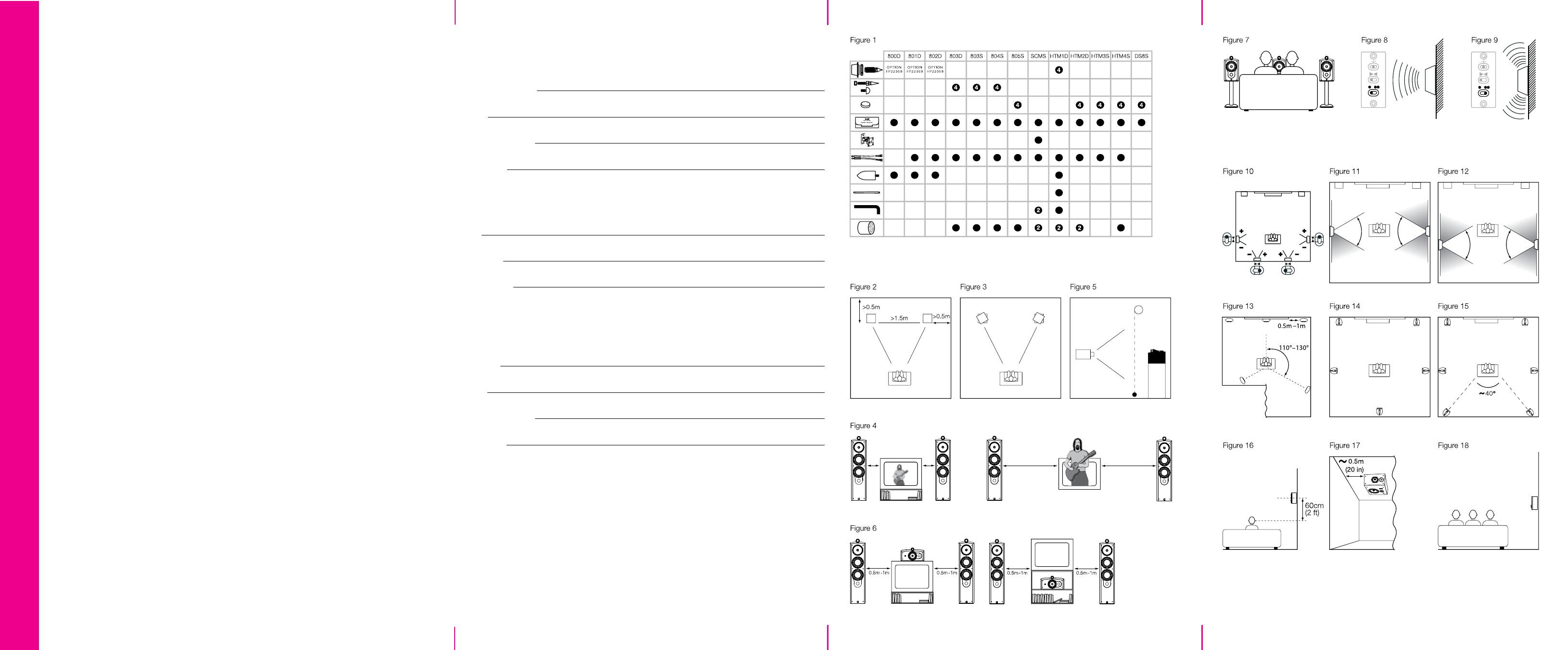
Different accessories are packed
according to model. Use the chart of
figure 1 to check the contents for your
particular model.
Contact your dealer if there are any
missing items.
2
POSITIONING
Stray magnetic fields
If you are using speakers in a home
theatre set-up and you are using a CRT
screen (a traditional tube television or
back projector), make sure the picture is
not going to be distorted by stray
magnetic fields from the drive unit motor
systems. The following dedicated centre
speakers are magnetically shielded
because their application requires them
to be placed right next to the screen:
HTM1D
HTM2D
HTM3S
HTM4S
All other speakers in the Series should
be placed at least 0.5m (20-in) from such
screens. Some television brands are
particularly sensitive to magnetic fields
and may require extra spacing. Plasma
and LCD screens are not affected and
front projectors are usually well away
from the speakers anyway.
Application
f
Go to
Front left and right
2.1
Front centre
2.2
Surround
2.3
2.1
FRONT LEFT AND RIGHT
If you're only interested in audio and not
movies, space the speakers apart
approximately the same distance as you
sit from them. This means that the
included angle is about 60º. This applies
whether or not you are using a centre
speaker.
Apart from the dedicated on-wall model
SCMS, the balance of the speaker is
more natural if the speakers are at least
0.5, (20-in) from the rear wall. This also
helps to improve the impression of
perspective. (figure 2)
If you are only concerned with 2-channel
audio, having the speakers further apart
can lead to what is known as the hole-in-
the-middle effect, where it's difficult to
generate a stable phantom central
image. If you have a centre speaker, you
can space the left and right speakers
further apart. All that happens is that the
image widens. It's just like being closer
to the performance.
If you have to space the speakers further
apart because of domestic constraints,
the central image can often be improved
if you toe the speakers in towards the
centre of the listening area. This can also
help the perception of the central image
for any listeners sitting away from the
centre line of the installation. (figure 3)
2
Most films are originally balanced for
cinemas, where a large number of
speakers spread around the auditorium
are used to create the surround sound
field. In that case there are more
surround speakers than there are discrete
channels of information and a less
precise image is created that gives an all-
enveloping effect. Dipoles and similar
diffuse speakers are better at recreating
this type of sound field in the home, but
using fewer speakers to do it. Image
positioning with these types of speaker is
never as precise as it can be with
monopoles. However, they do have the
advantage of making it easier to balance
the system for a larger listening area.
You may well receive conflicting advice
from different sources on the best type of
surround speaker to use. The truth is
that there is no one perfect solution for
all situations and the final choice for any
given application will be influenced by
several criteria, some of which may have
a degree of conflict.
DS8S only
Within the 800 series, the DS8S is the
only speaker to offer dipole operation.
In fact, this specialist surround speaker
has the advantage of offering a choice
of both monopole and dipole
operation, either via a switch located
on the front baffle, behind the
removable grille, or remotely, using a
12V trigger from the surround
processor. You may therefore choose
whichever type of operation best suits
the conditions of the listening room, the
size of audience and the type of
programme being played. Indeed, you
may even change the characteristic for
different types of programme and, as
the total energy into the room is the
same in both modes, no recalibration
of the installation is necessary when
switching between them.
In monopole mode, only the two drive
units on the front face operate. In
dipole mode, the front tweeter is
disconnected; the side firing drivers are
brought into operation and the
crossover frequency to the bass unit is
lowered. The drive units on opposing
sides are connected out of phase with
one another, which creates a wedge-
shaped null zone, approximately 60º
wide, at right angles to the wall. If the
listeners sit within this zone, they
become less aware of the location of
the speakers and hear more reflected
sound; hence the diffuse nature of the
sound field.
Use the bottom switch on the front
baffle when selecting between
monopole and dipole modes. In the
• position, the speaker defaults to
monopole. (figure 8)
However, if a 12V signal is applied to
the trigger input, internal relays switch
to dipole mode. In the •• position, the
speaker is always in dipole mode,
whatever the trigger signal. (figure 9)
Set the direction of the positive and
negative dipole lobes using the centre
toggle switch marked
><
on the front
baffle. The stem of the switch points in
the direction of the positive lobe.
For the smoothest panning of sounds
between all the speakers in the
installation, side speakers for all
applications and rear speakers for 6.1
and 7.1 applications should have the
polarity of the lobes set according to
figure 10.
Application
f
Go to
5.1 channel surround
2.4
6.1 and 7.1 channel side
2.5
6.1 channel rear
2.6
7.1 channel rear
2.7
2.4
5.1 CHANNEL SURROUND
DS8S only
If you are using the DS8S in dipole
mode only, place the speakers on the
side walls approximately 60cm (2 ft)
above ear height and in line with the
centre of the listening area. (figure 11)
If you are using the DS8S and switching
between dipole and monopole modes
for different applications, place the
speakers on the side walls
approximately 60cm (2 ft) above ear
height and slightly behind the centre of
the listening area, keeping the listeners
within the 60º wide null zone. (figure 12)
All models except DS8S
Place the speakers approximately 120º
round from front centre. The shape of
the room will dictate whether they are
placed on a side or rear wall. (figure 13)
f
Go to section 2.8
2.5
6.1 AND 7.1 CHANNEL SIDE
Place the speakers to the side, in line
with the centre of the listening area.
(figures 14 & 15)
f
Go to section 2.8
2.6
6.1 CHANNEL REAR
The rear channel of 6.1 EX recordings
may be reproduced by a single speaker
placed directly behind the centre of the
listening area. (figure 14)
f
Go to section 2.8
If you are also using the speakers for
movies, you should try to match the
audio image to the size of the screen.
That generally means that the speakers
should be closer together. A good
starting point is to put the speakers
about 0.5m (20-in) from the edges of the
screen. (figure 4)
Bookshelf or on-wall speakers should be
placed at a height that brings the
tweeters approximately to ear level. In
the vertical plane, the dispersion narrows
in the crossover region between the
midrange and tweeter drive units, when
both units are working together. To
preserve the optimum sound balance, try
to keep within ±5º of this.
Floor-standing speakers have the angle
of their optimum listening window
adjusted for the height of the speakers
and the typical range of ear height of
seated listeners.
f
Go to section 3.
2.2
FRONT CENTRE
If you have an acoustically transparent
screen, place the speaker behind the
centre of the screen. Angle it towards the
listeners if the tweeter is more than 5º
from ear height. (figure 5)
If you have a normal screen, place the
speaker immediately above or below the
screen, whichever is nearest ear height.
Angle it towards the listeners if the
tweeter is more than 5º from ear height.
A stand with tilt adjustment is available
for the HTM2D, HTM2S and HTM4S.
Consult your dealer for details. (figure 6)
If you are just listening to audio, place
the speakers centrally and mount
bookshelf or wall mount speakers with
the tweeters at ear height. (figure 7)
f
Go to section 3.
2.3
SURROUND
Surround speakers generally fall into two
main types – those that one might
describe as 'normal' speakers – so-
called monopoles, where the sound
comes from a set of drive units mounted
on the front of the enclosure – and those
that give a more diffuse sound field, such
as dipoles. Each type has its
advantages.
Most multi-channel music is recorded
with home entertainment in mind and is
monitored using monopole surround
speakers, whatever the multi-channel
recording format. This enables better
location of side and rear images,
although the formation of such images is
never quite as precise as it is between
the front speakers.
3
2.7
7.1 CHANNEL REAR
These recommendations may also be
used for a 6.1 channel system using two
speakers at the rear, wired in parallel to
the same channel.
Place two speakers behind the listening
area to make an angle of approximately
40º to the centre of the listening area.
(figure 15)
f
Continue to section 2.8
2.8 SURROUND SPEAKER HEIGHT
If you use the system for movies, place
the speakers approximately 60cm (2 ft)
above ear height. (figure 16)
This is also the preferred height for the
dipole mode of the DS8S in all
applications, although it may also be
mounted on the ceiling. Try to keep it
around 0.5m (20 in) from the side wall.
(figure 17)
For all other models, if you are listening
to audio only and there are only one or
two listeners, mount bookshelf speakers
with the tweeters approximately at ear
height.
If there are more listeners, raise the
speakers just above head height to avoid
obstructing the sound to any listener.
(figure 18)
f
Continue to section 3.
3
MOUNTING
Model
f
Go to
800D/801D/802D
3.1
HTM1D 3.2
803D/803S/804S
3.4
805S/HTM2D/HTM3S/HTM4S 3.5
SCMS
3.6
DS8S
3.7
3.1
800D/801D/802D
On delivery, the speakers are fitted with
roller glides to aid movement. Because
of the extreme weight of these speakers,
the rollers can cause indentation of
wooden and other vulnerable floor
surfaces. You should therefore take steps
to protect such surfaces by using an
intermediate layer such as floor tiles or
thick felt. The latter will allow you to glide
the speakers over smooth surfaces if you
push the cabinet low down.
Bass performance may be enhanced by
using the optional adjustable feet. These
are produced separately in a pack of 4
(800 Series Floor Spike Kit, part no.
FP22359). They have 40mm (1.6 in) of
vertical adjustment, allowing a certain
degree of tilt if desired, and are
reversible, having a spike for carpets on
one end and a clear rubber pad for
vulnerable surfaces on the other.
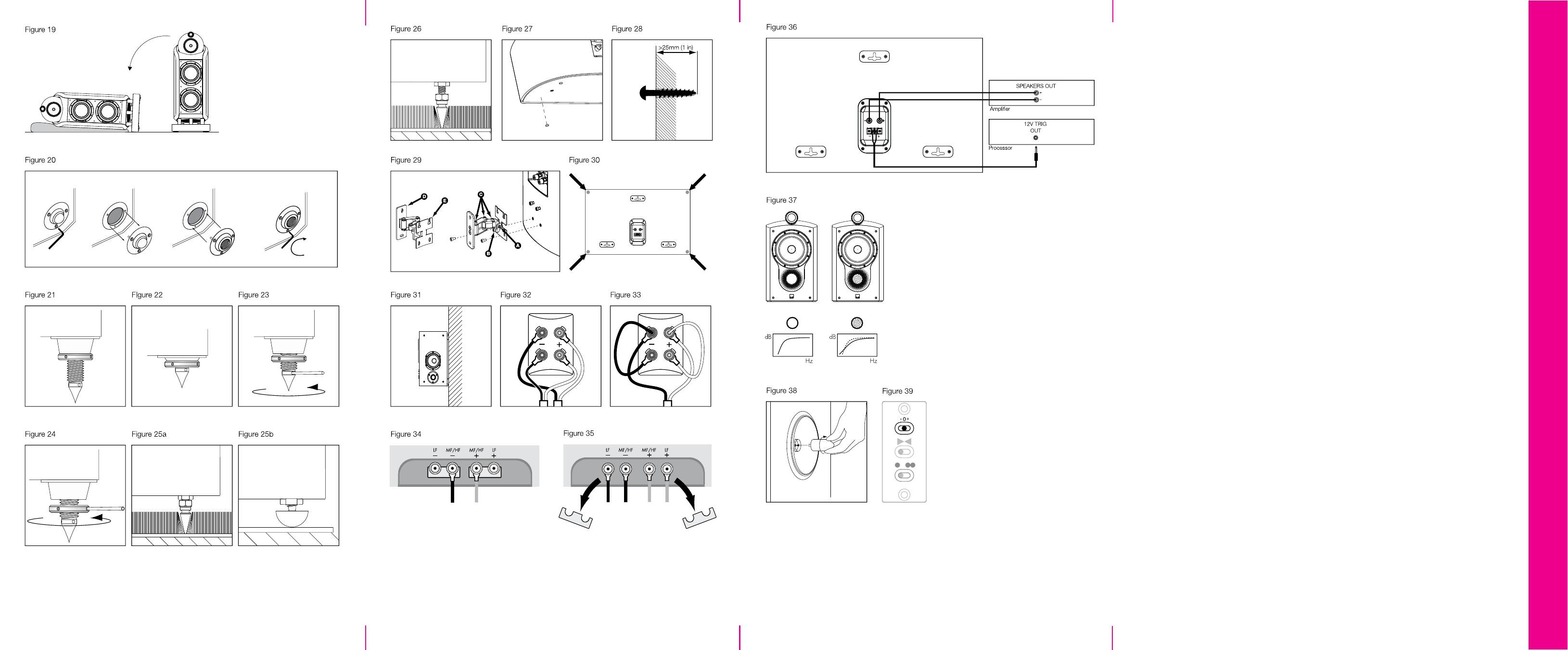
To fit the optional feet, first lay the
speaker down on its side (to avoid
possible damage to terminals or drive
unit diaphragms). (figure 19)
Due to the weight of the speaker, this
should be done by at least two people.
Remove rings and other jewellery to
avoid scratching the surfaces and
provide a soft surface such as a piece of
carpet that the speaker can lie on. You
may also like to wear non-slip gloves.
Do not be afraid to handle the speaker
by lifting on the side of the spherical
midrange 'head'. It is a little unnerving,
because the head is flexibly mounted on
the bass cabinet, but it does come to a
stop and is strong enough to take the
weight of the speaker.
Using the Torx key supplied with the kit,
remove the 4 roller glides from the plinth
of the speaker and replace them with the
feet. (figure 20)
Adjust the feet as described in section 3.3.
f
Go to section 3.3.
3.2
HTM1D
Supplied with the speaker are
4 adjustable feet and screws for fitting
them to the cabinet. They have 40mm
(1.6 in) of vertical adjustment, allowing tilt
up to 8º if desired. This is useful, as the
most common situation will be for the
speaker to be mounted on the floor
under a large screen.
The feet are reversible, having a spike for
carpets on one end and a clear rubber
pad for vulnerable surfaces on the other.
Fit the feet during the unpacking
procedure when the underside of the
cabinet is exposed. This allows the inner
packing pieces to remain in place against
the underside of the cabinet as
protection whilst the speaker is rolled
over into the upright position, and be
easily removed afterwards.
First read section 3.3 to familiarise
yourself with the design. If the speaker is
to be tilted back, fit the front threaded
bosses with the cones facing outwards
(figure 21) and the rear ones with the
cones facing inwards (figure 22). This is
as illustrated on the separate sheet
placed in the carton.
Screw in the feet with locking ring
attached, with either the spikes or rubber
tips outermost, according to the type of
floor surface. Leave the tips of the feet
protruding beyond the inner packing
pieces for clearance when the speaker is
upright.
After rolling the cabinet onto its feet and
lifting off the carton, remove the inner
packing and adjust the feet as described
in section 3.3
f
Continue to section 3.3.
3.3
ADJUSTING THE FEET
The threaded bosses that hold the feet
have a large conical shape on one side
of the flange. For maximum height, fit the
bosses with the conical shape towards
the floor. (figure 21) For minimum height,
have them pointing into the speaker.
(figure 22)
Screw in the feet close to where you
think the final adjustment will be, with the
spikes or the rubber ends outermost as
appropriate to the floor surface. If you do
not intend to tilt the speakers, orient the
bosses with the cones inwards and leave
just enough thread exposed to fit the
locking rings. Fit, but do not tighten the
locking rings.
Stand the speaker upright and adjust the
feet using the metal bar provided to give
the amount of tilt required and to take up
any rocking. (figure 23)
Finally, tighten the locking ring against
the boss, again using the metal bar.
(figure 24)
f
Go to section 4.
3.4
803D/803S/804S
For best performance, screw the
adjustable feet into the threaded inserts
in the base of the speaker as appropriate
– spikes for carpets or clear rubber for
wooden and other vulnerable floors.
(figure 25)
Lay the speaker down on its side (to
avoid possible damage to terminals or
drive unit diaphragms). Remove rings
and other jewellery to avoid scratching
the surfaces and provide a soft surface
such as a piece of carpet that the
speaker can lie on.
Screw the lock nuts fully onto the feet
and the feet fully into the base.
(figure 25)
Stand the speaker upright and adjust the
feet to take up any rocking.
Finally, tighten the locking rings against
the threaded inserts. (figure 26)
f
Go to section 4.

4
3.5
805S/HTM2D/HTM3S/HTM4S
These systems should be mounted on a
firm shelf or stand that allows the sound
to be properly directed to the listeners.
For the 805S, we recommend the use of
the FS-N805 stand that supports the
speaker at the correct listening height.
For the HTM2D, HTM3S and HTM4S,
the FS-NHTM stand supports these
centre speakers low down so that the
top of the speaker is no higher than
60cm (2 ft) from the floor, commensurate
with positioning them below a large
screen. The stand allows the speaker to
be tilted back by 0º, 4º or 8º.
Follow the instructions supplied with the
stand in each case.
When mounting the speakers on a
bookshelf, stick the 4 self-adhesive
rubber feet to the base of the speaker.
(figure 27)
f
Go to section 4.
3.6
SCMS
The speaker is designed to be fixed to a
wall and is supplied with a bracket that
allows adjustment of both horizontal and
vertical angles. (figure 29) The bracket
should be fixed to the wall using screws
in the range 5mm to 6mm diameter
(No.10 to No.12). The screw length
should be chosen to give a minimum of
25mm (1 in) engaged thread. (figure 28)
Hold the template provided against the
wall in the desired position and use a
spirit level to line it up properly. The
outside dimensions of the template
correspond to the rear of the cabinet.
Note especially that the centre of the wall
plate does not coincide with the centre
line of the speaker.
Mark the fixing holes on the wall and drill
and plug the wall.
Ensure that the screw length and
wall plug security are sufficient to
hold the weight of the speaker. When
fixing to drywall construction, try to
arrange for the screws to go into a
stud. B&W can accept no liability for
any failure of wall or ceiling fixings.
Screw the wall plate D to the wall and
test the firmness.
Part screw two of the supplied machine
screws into the upper two threaded
inserts in the back of the cabinet.
Offer the speaker up to the speaker plate
E, locating the two screw projecting from
the back of the speaker into the slots at
the top of the plate.
Fit the remaining two machine screws
through the plate E into the lower
threaded inserts in the cabinet and
tighten all four.
Set the vertical angle of the speaker by
adjusting screw B.
Fully tighten screw A.
Adjust screws C so that the friction of
the three vertical hinges allows you to
adjust the bracket but hold it in place
once set.
Connect the speakers as described in
section 4 before continuing.
Set the required horizontal angle and
push the speaker back to the wall, but
leave a little clearance to avoid rattles.
f
Go to section 4.
3.7
DS8S
The speakers may be fixed to a wall or
ceiling using screws in the range 5mm to
6mm diameter (No.10 to No.12).
On the back of the cabinet are three wall
plates. The screw head should be
inserted into the round part of the
aperture and slid fully along one of the
slots. The slots are sprung loaded to
prevent the speaker being readily
knocked out of position. The screw
length should be chosen to give a
minimum of 25mm (1 in) engaged thread.
(figure 28)
Ensure, especially when fixing to drywall
panels, that the screw length and wall
plug security are sufficient to hold the
weight of the speaker. B&W can accept
no liability for any failure of wall or ceiling
fixings.
Use the template provided to mark the
screw positions. The outside dimensions
of the template correspond to the rear of
the cabinet.
Stick 4 of the clear self-adhesive rubber
pads to the rear panel of each speaker,
one close to each corner. These stop the
speaker vibrating against the surface and
help keep it in position. (figure 30)
Adjust the protrusion of the screws such
that the rubber pads are a friction slide
on the surface when the wall plates are
hooked over the screw heads. (figure 31)
Always check and ensure that:
•
All the screws slide right to the
ends of the slots in the wall
plates.
•
Screw protrusion is adjusted so
that the rubber pads provide
enough friction to prevent the
speakers sliding out of position.
f
Go to section 4.
4
CONNECTIONS
All connections should be made with the
equipment switched off.
The terminals accept a variety of cable
terminations to suit most applications –
4mm banana plugs, 6mm and 8mm
(1/4 in and 5/16 in) spades, or bare wires
up to 6mm (1/4 in) diameter.
Important safety notice
In certain countries, notably those in
Europe, the use of 4mm banana
plugs is considered a potential safety
hazard, because they may be
inserted into the holes of
unshuttered mains supply sockets. In
order to comply with European
CENELEC safety regulations, the
4mm holes in the ends of the
terminals are blocked by plastic pins.
If you are using the products in any
country where these conditions
apply, you should ensure that any
banana plugs cannot be used in an
unsafe manner by children or other
uninformed persons.
Ensure each positive terminal on the
speaker (coloured red and marked +) is
connected to the positive output terminal
of the amplifier and negative (coloured
black and marked -) to negative.
Incorrect connection may result in
impairment of frequency response, poor
imaging and loss of bass.
Always screw the terminal caps down
fully to prevent rattles.
Model
f
Go to
DS8S
4.3
All other models
Continue
All models in the range except for the
DS8S may be bi-wired or bi-amplified. In
3-way systems, one set of terminals
feeds the bass drivers and the other the
midrange and tweeter. In 2-way systems,
one set of terminals feeds the bass/
midrange driver and the other the tweeter.
Separation of the signal paths to each
section of the speaker can improve
imaging and the resolution of low-level
detail, and allows the user to optimise
the cable to the frequency range of use.
Bi-wiring involves the use of two
separate 2-core cables from the same
amplifier, one to each pair of terminals.
This is the minimum we would
recommend, but should you prefer to
single wire, perhaps during the initial set-
up procedure or because you do not
want to see a multitude of cables in the
room, you must connect both positive
and both negative speaker terminals
together.
5
The ear is at its most sensitive in the
midrange, so we recommend that, when
single wiring, you connect the cable from
the amplifier to the terminals that directly
feed the midrange driver.
Bi-amplification goes a stage further and
involves the use of two separate power
amplifier channels for each speaker. It is
not the same as having a fully active
system, because the speaker's internal
passive crossover is still used.
If using bi-amplification, ensure that each
amplifier channel has the same gain,
otherwise you will change the balance of
the speaker. Check the absolute polarity.
Some amplifiers invert the signal, and a
mixture of different types may cause a
dip in the overall response. If you have a
mixture of inverting and non-inverting
amplifiers, reverse the polarity of the
connections from any inverting amplifier
to the speaker.
Bear in mind that, even though midrange
and, even more so, tweeter drivers can
(and only need to) handle less
continuous power than bass drivers, the
amplifier feeding them needs to have an
adequate voltage swing in order to
supply the short-term high-frequency
peaks in music without distortion. A high
voltage capability implies high power, so
it is not particularly desirable to have a
lower powered amplifier feeding the
midrange and tweeter than is used for
bass drivers.
Model
f
Go to
800D
4.2
All other models (not DS8S) Continue
On delivery, the two pairs of terminals are
electrically separate from one another
ready for bi-wiring. (figure 32)
For single wiring, short cables are
provided to link both positive and both
negative terminals together. Each cable
carries a spade connector at one end
and a 4mm banana plug at the other.
When single wiring, connect the cable
from the amplifier to the lower terminals
on 2-way systems (805S, HTM4S,
SCMS) and the upper terminals on
3-way systems.
On these terminals, use the opposite
type of connector on the link cables to
what you have terminating your main
cable. For example, if your main cable
terminates in spade connectors or bare
wires, use the banana plug end of the
link cables in the same terminals.
(figure 33)
f
Go to section 5.
4.2
800D
On delivery, both positive and both
negative terminals are connected
together by link plates.
When single wiring, leave these links in
position and connect the cable from the
amplifier to the centremost pair of
terminals. (figure 34)
When bi-wiring or bi-amplifying, remove
the links after loosening the lower, larger
diameter terminal caps. (figure 35)
The 4mm hole in the end of the terminal
post features a collet that may be
tightened around a banana plug using
the upper, smaller diameter terminal cap.
f
Go to section 5.
4.3
DS8S
In addition to the normal speaker
terminals, there is an additional pair of
screw terminals to operate an internal
12V relay that switches the speaker
between monopole and dipole modes
from a remote trigger. (figure 36)
You cannot use this facility if:
a Your processor does not feature a
12V trigger at all.
b Your processor only offers a simple
trigger that outputs a 12V signal when
the unit is switched on. This can only
be used to switch other equipment on
and off at the same time.
Some of the most expensive processors
allow you to assign a trigger to the type
of programme being played. They
recognise information on the disc that
distinguishes between movies and multi-
channel music. Others allow you to
assign triggers to different inputs; so if,
for example, you use a multi-channel
SACD or DVD-A player for music and a
separate DVD player for movies, you can
set up a trigger accordingly.
The relay in the speaker needs a certain
amount of current to operate, so check
the specification of your processor first
before proceeding. You will need to draw
45mA for each speaker you want to
switch.
The relay in the speaker only works when
the manual switch is set to the monopole
(•) position. If there is no voltage to the
trigger input, the speaker stays
monopole. If a 12V DC signal is present,
the relay overrides the manual monopole
setting and switches the speaker to
dipole mode. If you have the switch set
to the dipole (••) position, the trigger
feature will not work.
f
Continue to section 5.
5
FINE TUNING
Before fine tuning, double check that all
the connections in the installation are
correct and secure.
Floor- and stand-mount speakers
only
Moving the speakers further from the
walls will reduce the general level of
bass. Space behind the speakers also
helps to create an impression of depth.
Conversely, moving the speakers closer
to the walls will increase the level of
bass.
803D, 803S, 804S, 805S, HTM1D,
HTM2D, HTM4S, SCMS only
These vented-box systems are
supplied with foam plugs fitted in the
ports. Normally, the speakers should
be used with these plugs removed for
maximum bass output, but if the bass
is too heavy due to room effects and
you cannot move the speakers further
from the walls, refit the plugs to reduce
the bass output. (figure 37)
If the bass is uneven with frequency, it is
usually due to the excitation of
resonance modes in the room
Even small changes in the position of the
speakers or the listeners can have a
profound effect on how these
resonances affect the sound. Try
positioning the speakers along a different
wall. Even moving large pieces of
furniture can have an effect.
For the most discerning listening, remove
bass and midrange grilles as
described in section 8 –
Aftercare.
Tweeter diaphragms are very
delicate and easily damaged. The
tweeter grilles are held in place with
magnetism and any mishandling of the
grille close to the tweeter may result in
the grille being attracted into the tweeter
diaphragm. For these reasons, we
recommend that you leave tweeter grilles
in place.
800D, 801D, 802D, HTM1D only
If you use these systems without the
midrange grille, replace the plastic
centre plug of the midrange drive unit
with the solid aluminium plug in the
accessory pack. Simply unscrew the
fitted plug and screw in the
replacement. Hand tighten only.
(figure 38)
If the sound is too harsh, increase the
amount of soft furnishing in the room (for
example, use heavier curtains), or reduce
it if the sound is dull and lifeless.

6
Test for flutter echoes by clapping your
hands and listening for rapid repetitions.
Reduce them by the use of irregular
shaped surfaces such as bookshelves
and large pieces of furniture.
DS8S only
In monopole mode, the high-frequency
output level may be adjusted using the
top toggle switch on the front baffle.
(figure 39)
In the centre 0 position, the system
response is nominally flat. The +
position gives more output, which may
be required, for example, if the acoustic
of the room is dull, if circumstances
dictate that the speakers have to be
placed more off line than
recommended, or if the speaker is built
into custom furniture and placed
behind fabric that is more absorbent
than that on the grilles supplied.
Conversely, the – position reduces the
level for when the room acoustic is too
bright or if you want to reduce your
awareness of the speakers' location.
Experiment to find the mode settings
best suited to your requirements.
Typical combinations are:
•
All surround speakers monopole.
•
Side speakers dipole, rear speakers
monopole.
•
All surround speakers dipole.
It would be unusual, but not
impossible, to set side speakers to
monopole and rear speakers to dipole.
6
RUNNING IN
The performance of the speaker will
change subtly during the initial listening
period. If the speaker has been stored in
a cold environment, the damping
compounds and suspension materials
will take some time to recover their
correct mechanical properties. The drive
unit suspensions will also loosen up
during the first hours of use. The time
taken for the speaker to achieve its
intended performance will vary
depending on previous storage
conditions and how it is used. As a
guide, allow up to a week for the
temperature effects to stabilise and
15 hours of average use for the
mechanical parts to attain their intended
design characteristics.
However, longer run-in periods (as long
as a month) have been reported and
there is evidence to suggest that this has
little to do with the speaker changing and
more to do with the listener getting used
to a new sound. It is especially so with
highly revealing speakers such as these,
where there may be a significant increase
in the amount of detail portrayed
compared to what the listener has
previously been used to; the sound may
at first appear too “up front” and perhaps
a little hard. After an extended period of
time, the sound will seem to mellow, but
without losing clarity and detail.
7
ANCILLARY EQUIPMENT
Speakers of this ability deserve signals of
the highest quality. Choose your
electronic equipment and interconnecting
cables with care. We can give guidance
on what to look for when choosing
ancillary equipment, but cannot
recommend specific items. The
standards of such products are
improving all the time and your dealer will
be able to demonstrate a variety of
suitable up-to-date products.
In the specification we recommend a
range of amplifier powers. The higher
figure is defined by the power handling
capability of the speaker. When
calculating the power handling, it is
assumed that the amplifier is not run into
clipping, which distorts the frequency
power spectrum of the signal, and that
the signal is normal programme material.
Test tones from oscillators and the like
are not applicable. The lower figure is the
minimum we consider necessary to
achieve reasonable listening levels
without audible distortion in the smaller
room (less than 60 m
3
or 2000 cu ft). The
higher the power you use, the less likely
you are to experience amplifier clipping.
You can often tell how good an amplifier
is at driving complex speaker loads by
looking at its power rating into both 4
Ω
and 8
Ω
loads. The nearer the ratio is to
2:1 the better, as it indicates a good
current capability.
In order to reduce the effect the cable
has on the frequency response of the
speaker to inaudible levels, the
impedance of the cable at all frequencies
(measuring both positive and negative
conductors in series) should be kept as
low as possible and certainly below
0.1
Ω
. At low frequencies, the DC
resistance of the cable is the dominant
factor and you should choose a gauge of
wire sufficient to achieve the impedance
requirements over the length of cable
you need to use. At mid and high
frequencies the inductive component of
the impedance can dominate the DC
resistance. This and other properties
influenced by the detailed construction of
the cable become important. Ask your
dealer for advice on the best cable for
Оглавление
- EnglishOwner's manual
- Limited Warranty
- FrançaisMode d’emploi
- Garantie limitée
- DeutschBedienungsanleitung
- Garantie
- EspañolManual de instrucciones
- Garantía Limitada
- PortuguêsManual do utilizador
- Garantia limitada
- ItalianoManuale di istruzioni
- Garanzia limitata
- NederlandsHandleiding
- Beperkte garantie
- Περιορισµένη εγγύηση
- РусскийРуководство по эксплуатации
- Ограниченная гарантия
- MagyarKezelési útmutató
- Korlátozott garancia
- PolskiInstrukcja obs¡ugi
- Gwarancja
- Záruka
- SvenskaAnvändarmanual
