Bowers & Wilkins ASW CM: инструкция
Раздел: Бытовая, кухонная техника, электроника и оборудование
Тип: Акустика
Инструкция к Акустику Bowers & Wilkins ASW CM
ASW CM
Owner’s Manual
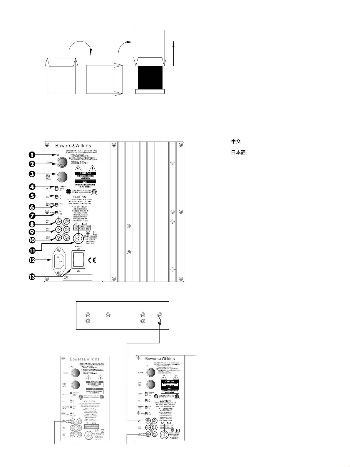
Figure 1
ASW CM Owner’s manual
English ...............................1
Français..............................4
Deutsch ..............................9
Español ............................13
Português ..........................17
Italiano .............................21
Nederlands .......................25
Ελληνικά .........................29
Русский...........................34
Figure 2
................................39
.............................42
Norsk...............................46
Svenska ............................47
Suomi...............................48
Figure 3
E60065-00
100-230V~ 50/60Hz 100W
SURROUND
CENTRE
FRONT
SUBWOOFER
L
L
R
R
Decoder
No.2
No.1
E60065-00
E60065-00
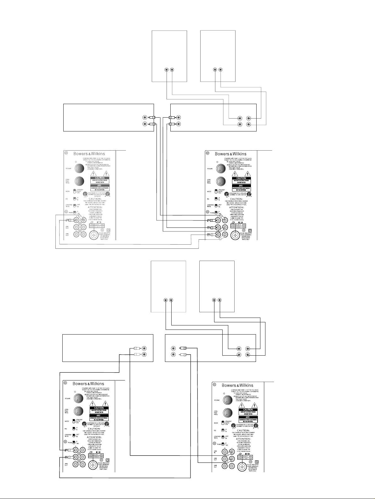
Figure 4
Figure 5
RIGHT
LEFT
-
++
-
LINE OUT
LINE IN
SPEAKERS OUT
R
L
L
L
+
R
R
-
Pre-Amplifier
Power Amplifier
NO.2
NO.1
E60065-00
RIGHT
LEFT
-
++
-
LINE OUT
LINE IN
SPEAKERS OUT
R
L
L
L
+
R
R
-
Pre-Amplifier
Power Amplifier
NO.2
No.1
E60065-00
unable to insert the plug fully into the outlet,
result in a fire or electric shock. Never spill
IMPORTANT
try reversing the plug. If the plug should still
liquid of any kind on the product. Do not
fail to fit, contact your electrician to replace
place any object containing liquid on top of
SAFETY
your obsolete outlet. Do not defeat the safety
the product.
purpose of the polarised plug. When using
15 Cleaning – Unplug the product from the
INSTRUCTIONS
an extension power-supply cord or a power-
wall outlet before cleaning. The cabinet of
supply cord other than that supplied with the
the subwoofer may be cleaned by dusting
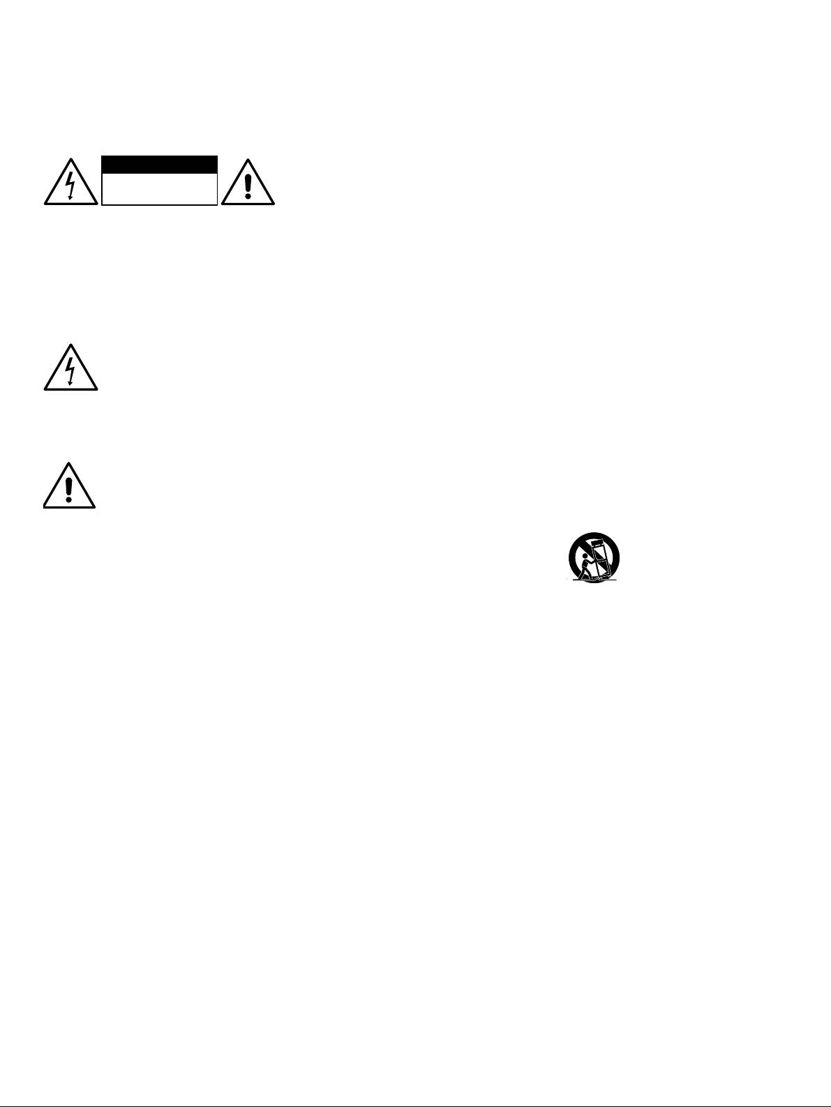
CAUTION
appliance, it should be fitted with the
with a dry cloth. If you wish to use an
appropriate moulded-on plugs and carry
RISK OF ELECTRIC SHOCK
aerosol cleaning spray, do not spray directly
DO NOT OPEN
safety approval appropriate to the country of
on the cabinet; spray onto the cloth. Remove
use.
the grille first so that the cloth does not
Caution:
8
Power Cord Protection – Power-supply
become stained, but be careful not to disturb
cords should be routed so that they are not
the drive unit. The grille itself may be
To reduce the risk of electric shock, do not
likely to be walked on or pinched by items
cleaned using a soft brush.
remove the back panel and do not expose the
placed on or against them, paying particular
apparatus to rain or moisture. No user-
16 Attachments – Do not use attachments not
attention to cords at plugs, convenience
serviceable parts inside. Refer servicing to
recommended by the product manufacturer,
receptacles and the point where they exit
qualified personnel.
as they may cause hazards.
from the appliance.
Explanation of Graphical Symbols:
17 Accessories – Do not place this product
9 Overloading – Do not overload wall
on an unstable cart, stand, tripod, bracket or
The lightning flash within an
outlets, extension cords or integral
table. The product may fall, causing serious
equilateral triangle is intended to
convenience receptacles, as this can result in
injury to a child or adult, and serious
alert you to the presence of
a risk of fire or electric shock.
damage to the product. Use only with a
uninsulated “dangerous voltage”
10 Ventilation – The amplifier panel at the
cart, stand, tripod, bracket or table
within the product’s enclosure that
rear of the product forms part of the cooling
recommended by the manufacturer or sold
may be of sufficient magnitude to
mechanism and must not be obscured by
with the product. Any mounting of the
constitute an electric shock to
placing the product on a bed, sofa, rug, or
product should follow the manufacturer’s
persons.
other similar surface. Do not cover the
instructions and should use a mounting
The exclamation point within an
amplifier panel with any items such as
accessory recommended by the
equilateral triangle is intended to
tablecloths, newspapers, etc. Ensure the heat
manufacturer.
alert you to the presence of
sink fins are aligned vertically to ensure
18 Moving the appliance – A product and
important operating and
proper cooling. There should be a clear gap
cart combination should be moved with
maintenance (servicing) instructions
of at least 50mm (2-in) between the back of
care. Quick stops, excessive
in the literature accompanying the
the product and any wall or partition. If the
force and uneven surfaces may
appliance.
product is placed in a built-in installation,
cause the product and cart
such as a rack, bookcase or cabinet, proper
WARNINGS:
combination to overturn. Check
provision for air to circulate must be
1
that there are no cables under
1 Read Instructions – All the safety and
provided, either by a) 12mm (
/
2
-in) clear
the carpet that may be damaged by the
operating instructions should be read before
gap round the top, sides and bottom of the
spike feet. Do not walk the product on the
the appliance is operated.
product venting into the room or b) two ducts
spike feet as this may cause them to become
of 150 sq cm (24 sq in) minimum cross
2 Retain Instructions – The safety and
detached from the cabinet and cause
section from the room leading to slots
operating instructions should be retained for
damage. Take care not to impale yourself
300mm (12-in) wide x 50mm (2-in) deep at
future reference.
with the spike feet.
top and bottom of the compartment, in line
3 Heed Warnings – All warnings on the
with the gap behind the product.
19 Non-use Periods – The power cord of
appliance and in the operating instructions
the appliance should be unplugged from the
11 Heat – The product should be situated
should be adhered to.
outlet during lightning storms or when the
away from heat sources such as radiators,
apparatus is left unused for a long period of
4 Follow Instructions – All operating and
heat registers, stoves, or other products
time.
use instructions should be followed.
(including amplifiers) that produce heat. No
naked flame sources, such as lighted
20 Servicing – Do not attempt to service this
5 Installation – Install in accordance with
candles, should be placed on the apparatus.
product yourself, as opening or removing
the manufacturer's instructions.
covers may expose you to dangerous
12 Wall or Ceiling Mounting – The
6
Power Sources – This product should be
voltage or other hazards. Refer all servicing
product should be mounted to a wall or
operated only from the type of power source
to qualified service personnel.
ceiling only as recommended by the
indicated by the marking situated on the rear
manufacturer.
21 Damage Requiring Service – Unplug
panel. If you are not sure of the type of
this product from the wall outlet and refer
power supply to your home, consult your
13 Water and Moisture – To reduce the risk
servicing to qualified personnel under the
product dealer or local power company.
of fire or electric shock, do not expose the
following conditions:
product to rain or excessive moisture such as
7
Grounding or Polarisation – The
in a sauna or bathroom. Do not use this
a When the power-supply cord or plug has
appliance is not required to be grounded.
product near water – for example, near a
been damaged.
Ensure the plug is fully inserted into the wall
bathtub, washbowl, kitchen sink, laundry
outlet or extension cord receptacle to prevent
b If liquid has been spilled or objects have
tub, in a wet basement, or near a swimming
blade or pin exposure. Some versions of the
fallen into the appliance.
pool and the like.
product are equipped with a power cord
c If the product has been exposed to rain or
fitted with a polarised alternating line plug (a
14 Object and Liquid Entry – Never push
water.
plug having one blade wider than the other).
objects of any kind into this product through
This plug will fit onto the power outlet only
openings, as they may touch dangerous
d If the product does not operate normally
one way. This is a safety feature. If you are
voltage points or short out parts that could
by following the operating instructions.
1
Adjust only those controls that are covered
improves the midrange clarity by reducing the
Positioning the subwoofer
by the operating instructions, as an
low-frequency demands on your existing speakers.
Because the subwoofer produces only low-
improper adjustment of other controls may
Please read through this manual fully before
frequency sounds, positioning is less critical in
result in damage and will often require
using the subwoofer. All sound installations
some respects compared to full-range speakers.
extensive work by a qualified technician to
require some planning and experimentation if
Directional information is much less precise and
restore the product to its normal operation.
you are to get the best out of the products used
you have more choice where to place the
e If the product has been dropped, or
and this manual will guide you in this process.
speakers to good effect. This said, best results
damaged in any way.
are obtained if the subwoofer is placed between
As the subwoofer is connected to the electricity
the satellite speakers or in the vicinity of one of
f When the product exhibits a distinct
power supply, it is important that you familiarise
them. If you use two subwoofers, it is best to put
change in performance – this indicates a
yourself with the safety instructions and heed all
one near each satellite speaker.
need for service.
warnings.
Placing the subwoofer behind the listeners, even
22
Replacement Parts – When replacement
Keep this manual in a safe place for future
in surround sound installations, generally gives
parts are required, be sure the service
reference.
inferior imaging, but may be an acceptable
technician has used replacement parts
B&W products are distributed to over
compromise if domestic considerations dictate.
specified by the manufacturer or have the
60 countries worldwide and we maintain an
same characteristics as the original part.
As with all speakers, the proximity of room
international network of carefully chosen and
Unauthorised substitutions may result in fire,
boundaries affects the sound. Bass is generally
dedicated distributors. If you have a problem,
electric shock or other hazards.
increased as more surfaces come into close
which your dealer cannot resolve, our distributors
proximity with the speakers. Unlike full-range
will be more than willing to assist you.
speakers, however, you can always restore the
correct overall system balance by adjusting the
volume level of the subwoofer. The more boost
Unpacking
you get from the room, the less hard the speaker
(figure 1)
23 Mains Fuses – For continued protection
has to work; but there is a down side. Corner
against fire hazard, use fuses only of the
The easiest way to unpack the subwoofer and
positions often excite more low-frequency room
correct type and rating. The amplifier is
avoid damage is as follows:
resonances, making the bass more uneven with
designed to operate with nominal mains
frequency. There is no substitute for experiment
• Open the carton flaps right back and invert
supplies in the range 100V to 230V AC, but
as all rooms behave differently, so try the
the carton and contents.
different types of fuse are used, dependent
subwoofer in a variety of positions before
on the mains voltage. The correct fuse
• Lift the carton away from the product.
making a final decision. A piece of music with a
specification for each voltage range is
bass line ascending or descending the musical
We recommend that you retain the packaging
marked on the product.
scale is useful for assessing the smoothness of
for future use.
the bass response. Listen for exaggerated or
24 Safety Check – Upon completion of any
In addition to this manual, the carton should
quiet notes. Having a separate subwoofer does
service or repairs to this product, ask the
contain:
enable you to optimise for room resonances
service technician to perform safety checks
independently from siting the satellite speakers
to determine that the product is in proper
1 Subwoofer
for best imaging.
operating condition.
1 Accessory pack containing:
If the subwoofer is to be used in a confined
25 Magnetic Fields – the product creates a
4 Rubber feet
space (eg in custom furniture), the space must be
stray static magnetic field. Do not place any
ventilated to allow sufficient air to circulate and
object that may be damaged by this
4 Spike feet
cool the unit. Ask your dealer for advice.
magnetic field (eg cathode ray tube
4 Lock nuts
televisions or computer monitors, audio and
The subwoofer is supplied with four spike feet.
video tapes and swipe cards) within 0.5m
1 International warranty document
The spikes pierce through carpet pile, giving a
(2 feet) of the appliance. The appliance may
firm support directly to the floor surface without
cause distortion of cathode ray tube images
crushing the pile.
beyond this distance.
A tour of the subwoofer
If the unit is to be placed on a vulnerable
(figure 2)
surface, such as a wooden floor, either place a
1 Power/Standby indicator
protective disc under each spike or fit the four
Introduction
rubber feet in place of the spikes.
2 VOLUME control
Thank you for purchasing a B&W ASW Active
When fitting either the rubber feet or the spike
Subwoofer.
3 LOW-PASS FREQUENCY control
feet, first screw the lock nuts fully onto the thread
Since its foundation in 1966, the continuing
4 MODE On/Auto/Standby switch
and then screw the feet fully onto the threaded
philosophy of B&W has been the quest for
inserts in the base of the cabinet. If the unit
5 Equalisation switch
perfect sound reproduction. Inspired by the
rocks, loosen the relevant two opposing feet until
company’s founder, the late John Bowers, this
6 LOW-PASS FILTER defeat switch
the support is firm, then re-tighten the lock nuts to
quest has entailed not only high investment in
the inserts.
7 Phase switch
audio technology and innovation but also an
Check that there are no cables under the carpet
abiding appreciation of music and the demands
8 LINE IN
that may be damaged by the spike feet.
of film sound to ensure that the technology is put
9 LINE OUT
to maximum effect.
Do not walk the product on the spike feet as this
10 LINK OUT
may cause them to become detached from the
This subwoofer has been designed for Home
cabinet and cause damage.
Theatre installations and to augment the bass
11 Fuse holder
performance of full-range speakers in 2-channel
Take care not to impale yourself with the spike
12 Power input socket
audio use. Adding the subwoofer to your system
feet when moving the product.
not only extends the bass to lower frequencies, it
13 POWER on/off switch
2

Electrical connections
Double-check the connections
• The LOW-PASS FILTER switch (5)
Disconnect all sound system equipment from the
Before auditioning the sound quality of your new
• The EQ (equalisation) switch (4)
power supply until the signal connections have
installation and fine-tuning it, double-check the
The optimum settings depend on the other
been made and checked. This avoids the risk of
connections. All too often, users complain that
equipment used with the subwoofer. If using
damage whilst connections are made or broken.
they cannot get a decent sound however they set
more than one subwoofer, ensure the controls on
the controls, only to discover something has been
The function of the subwoofer is to receive
each one are set the same.
wrongly connected. Make sure that:
signals from the amplification chain and, where
Use with home theatre decoders
necessary for 2-channel audio, split the signal
• The phasing is correct – there should be no
®
into low bass and higher frequencies and feed
positive to negative connections to the
The B&W ASW Active Subwoofer is not a THX
the latter back out to the satellite speakers. Left
satellite speakers. If something is out of
licensed component, but may be used with a
and right channel inputs may be combined into
phase you may get a fuzzy sound with an
THX
®
controller if desired.
a single mono low bass feed to the subwoofer
imprecise and floating image, a lack of bass
• Set the VOLUME control to the half way
drive unit if required.
or a combination of the two.
(12 o’clock) position.
The subwoofer will input and output line-level
• There are no left to right mix-ups – this can
• The setting of the LOW-PASS FREQUENCY
signals via the RCA Phono sockets located on
result, for example, in the orchestra being the
control is irrelevant.
the back panel.
wrong way round or, more disastrously,
sounds on your Home Theatre going in the
• Set the PHASE switch initially to 0˚.
Use the following table to select the correct
opposite direction to the action on the
wiring method for your installation:
• Set the LOW-PASS FILTER switch to OUT.
screen.
Application: Home Theatre
• Set the EQ switch initially to position A.
The subwoofer may be used with any decoder
See also the section “Fine tuning”.
Switching on and off
that has a line-level subwoofer output (normally
If you have a THX
®
controller, ensure that the
from an RCA Phono socket). Most decoders with
We recommend that you switch the subwoofer
subwoofer function is enabled. When so
integral power amplifiers still output the
on before any power amplifiers receiving signals
configured it incorporates all the filtering and
subwoofer or Low-Frequency Effects (LFE) signal
from the subwoofer. Similarly, when switching
level setting required for the subwoofer in all
at line level.
off, switch the subwoofer off last.
modes. For level calibration, the internal test
®
• Decoder with one or more subwoofers –
The MODE standby/auto/on switch (3) at the
noise and channel level controls in the THX
fig. 3
top left of the amplifier panel does not isolate
controller should be used. In all cases the levels
the amplifier completely from the power supply. It
should be set to obtain 75dB SPL (C-weighted)
Application: 2-channel audio
maintains a low-power input to an auxiliary
at the listening position from the controller’s
Separate pre- & power amplifiers:
sensing circuit.
internal noise test signal.
a One or more subwoofers with output
The switch (3) operates as follows:
With other decoders, configure the front and
combined into a single mono signal – fig. 4
surround speakers to “large” or “small” as
On:
appropriate before setting the levels. Use the
b Two subwoofers with separate left and right
With the switch in this position, the amplifier
internal noise test signal and volume controls of
signal – fig. 5
remains permanently on, and the light glows
the decoder to set the levels of all the speakers.
green.
The subwoofer is not suitable for use with
Only change the VOLUME control on the
2-channel integrated pre/power amplifiers.
Auto:
subwoofer if there is not enough range in the
On first switching the subwoofer to Auto, the
decoder to achieve the correct levels.
amplifier becomes fully active and the light (10)
Inexpensive sound level meters are readily
Using more than one subwoofer
above the on/auto/standby switch glows green.
available from electronics stores and should be
After a period of about 5 minutes without an
Using more than one unit in a single installation
used to calibrate the levels. Refer to your
input signal, the amplifier automatically reverts to
can improve performance in the following ways:
decoder manual for further details on how to set
standby mode, and the light glows red. When
the levels.
• Maintain stereo separation to the lowest
an input signal is detected, the amplifier
frequencies.
automatically becomes fully active and the light
Use for 2-channel audio
glows green.
• Cope with larger listening rooms.
• Set the VOLUME control initially to the half
Standby:
way (12 o’clock) position.
• Enable greater maximum sound output –
In this position, the amplifier is in permanent
often useful for effectively reproducing
• Set the LOW-PASS FREQUENCY initially to
standby, and the light glows red.
special effects in Home Theatre applications.
80Hz.
If the subwoofer is to be out of use for an
• Smooth out the effects of low-frequency room
• Set the LOW-PASS FILTER switch to IN.
extended period of time, we recommend you
resonances.
isolate it from the power supply, either by using
• Set the EQ switch initially to position B.
If you are using two subwoofers for 2-channel
the POWER switch (10) or by removing the plug
• Set the PHASE switch initially to 0˚.
audio, separation is improved if each channel
from the power socket.
has its own subwoofer, providing each one is
See also the section “Fine tuning”.
placed close to the relevant satellite speaker.
Only use the mono connection of figure 4 if you
Setting the controls
cannot place each subwoofer close to its satellite
Fine-tuning
There are 5 controls to consider:
speaker.
There are two settings of the EQ switch. Position
• The VOLUME control (1)
A is optimised to allow the subwoofer to provide
• The LOW-PASS FREQUENCY control (2)
the highest listening levels, while position B gives
greater bass extension coupled with a tighter
• The PHASE switch (6)
sound.
3
