Bowers & Wilkins ASW2000: инструкция
Раздел: Бытовая, кухонная техника, электроника и оборудование
Тип: Микрофон
Инструкция к Микрофону Bowers & Wilkins ASW2000
ASW2000
OWNER’S MANUAL
ASW2000 Owner’s manual
English..........................................5
Français........................................
8
Deutsch
......................................11
Español......................................14
Português...................................17
Italiano.......................................20
Nederlands...............................23
Figure 1
Ελληνικ .................................26
...........................................29
Magyar......................................32
Polski..........................................35
Русский....................................38
Dansk...............................42
Svenska............................42
Norsk...............................42
Suomi...............................43
Figure 2
2
6
4
5
11
LINK
LINE
PHASE
LOW–PASS VOLUME
POWER
OUT
LINE
IN
OUT
L
ON
60
70
0 180
50
AUTO
R
80
7
10 0
OFF
14040
MIN MAX
TO SPEAKERS FROM AMPLIFIER
3
RIGHT
LEFT
RIGHT LEFT
™
ASW
2000
ACTIVE SUBWOOFER
1
1
WARNINGS:
TO PREVENT FIRE OR SHOCK HAZARD DO NOT EXPOSE THIS UNIT TO RAIN OR MOISTURE
NO USER SERVICEABLE PARTS INSIDE REFER SERVICING TO QUALIFIED PERSONNEL
ATTENTION:
POUR EVITER TOUS RISQUES DE FEU OU DE CHOC ELECTRIQUE
AUCUN COMPOSANT NE PEUT ETRE REMPLACE PAR L’UTILISATEUR
N’EXPOSEZ PAS CET APPAREIL A L’HUMIDITE
VEUILLEZ CONTACTER LE SERVICE APRES VENTE AGREE
9
ATTENTION: VOIR LE CAHIER D'INSTRUCTIONS
CAUTION: SEE OPERATING MANUAL
B&W LOUDSPEAKERS LTD
WORTHING ENGLAND
12
8
10
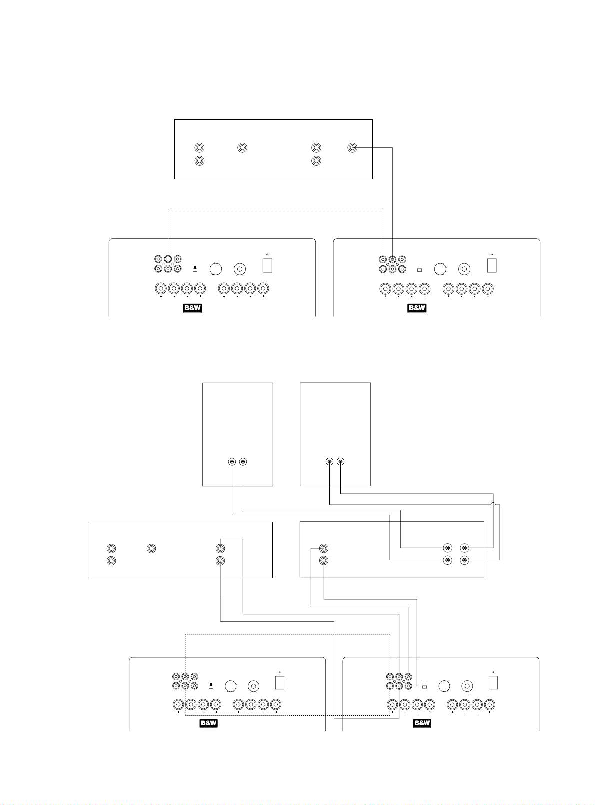
Figure 3
Figure 4
1
SURROUND
CENTRE
FRONT
SUBWOOFER
L
L
R
R
Decoder
LINK
OUT
LINE
IN
LINE
OUT
PHASE
LOW–PASS VOLUME
POWER
LINK
OUT
LINE
IN
LINE
OUT
PHASE
LOW–PASS VOLUME
POWER
L
60
ON
L
60
ON
50
70
70
0 180
80
AUTO
R
R
0 180
50
80
AUTO
100
OFF
100
OFF
14040
MIN MAX
14040
MIN MAX
TO SPEAKERS FROM AMPLIFIER
TO SPEAKERS FROM AMPLIFIER
RIGHT
LEFT
RIGHT LEFT
RIGHT
LEFT
RIGHT LEFT
ASW
™
2000
ASW
™
2000
ACTIVE SUBWOOFER
ACTIVE SUBWOOFER
No. 2 No. 1
RIGHT
LEFT
-
++
-
SURROUND
CENTRE
FRONT
LINE IN
SPEAKERS OUT
R
L
L
L
L
+
R
R
R
-
Decoder
Power Amplifier
LINK
OUT
LINE
IN
LINE
OUT
PHASE
LOW–PASS VOLUME
POWER
LINK
OUT
LINE
IN
LINE
OUT
PHASE
LOW–PASS VOLUME
POWER
L
60
ON
L
60
ON
0 180
50
70
50
70
80
AUTO
AUTO
R
R
0 180
80
100
OFF
100
OFF
14040
MIN MAX
14040
MIN MAX
TO SPEAKERS FROM AMPLIFIER
TO SPEAKERS FROM AMPLIFIER
RIGHT
LEFT
RIGHT LEFT
RIGHT
LEFT
RIGHT LEFT
ASW
™
2000
ASW
™
2000
ACTIVE SUBWOOFER
ACTIVE SUBWOOFER
No. 2
No. 1
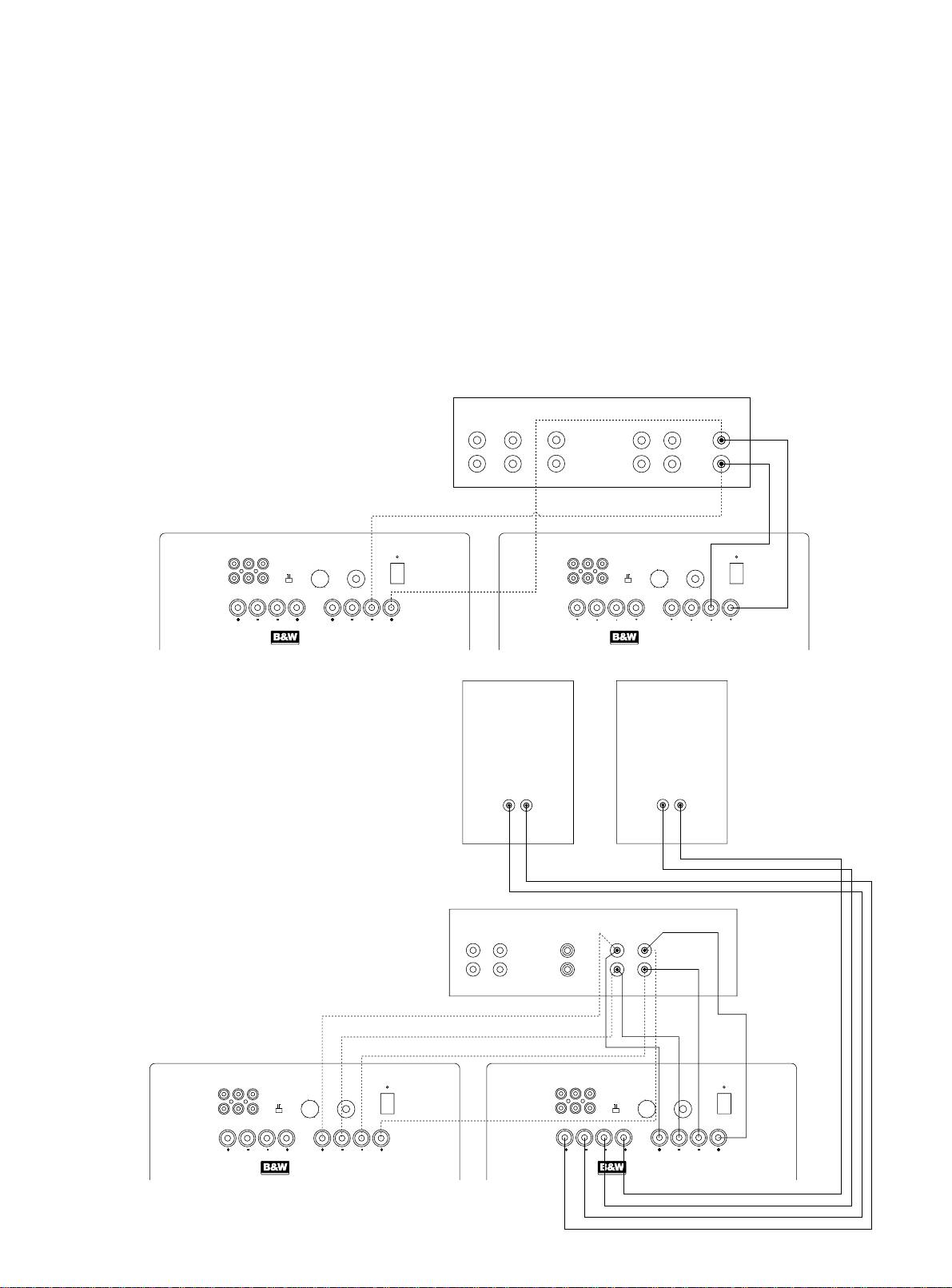
Figure 5
Figure 6
2
SURROUND
CENTRE
FRONT
SUBWOOFER
R
L
R
L
+
+
+
+
-
-
-
-
Integrated Decoder
LINK
OUT
LINE
IN
LINE
OUT
PHASE
LOW–PASS VOLUME
POWER
LINK
OUT
LINE
IN
LINE
OUT
PHASE
LOW–PASS VOLUME
POWER
L
60
ON
L
60
ON
0 180
50
70
70
AUTO
0 180
50
AUTO
R
80
R
80
100
OFF
100
OFF
14040
MIN MAX
14040
MIN MAX
TO SPEAKERS FROM AMPLIFIER
TO SPEAKERS FROM AMPLIFIER
RIGHT
LEFT
RIGHT LEFT
RIGHT
LEFT
RIGHT LEFT
ASW
™
2000
ASW
™
2000
ACTIVE SUBWOOFER
ACTIVE SUBWOOFER
No. 2
No. 1
RIGHT
LEFT
-
++
-
SURROUND
CENTRE
FRONT
R
L
R
L
+
+
+
-
--
Integrated Decoder
LINK
OUT
LINE
IN
LINE
OUT
PHASE
LOW–PASS VOLUME
POWER
LINK
OUT
LINE
IN
LINE
OUT
PHASE
LOW–PASS VOLUME
POWER
L
60
ON
L
70
60
ON
50
70
R
0 180
80
AUTO
R
0 180
50
80
AUTO
100
OFF
100
OFF
14040
MIN MAX
14040
MIN MAX
TO SPEAKERS FROM AMPLIFIER
TO SPEAKERS FROM AMPLIFIER
RIGHT
LEFT
RIGHT LEFT
RIGHT
LEFT
RIGHT LEFT
ASW
™
2000
ASW
™
2000
ACTIVE SUBWOOFER
ACTIVE SUBWOOFER
No. 2 No. 1
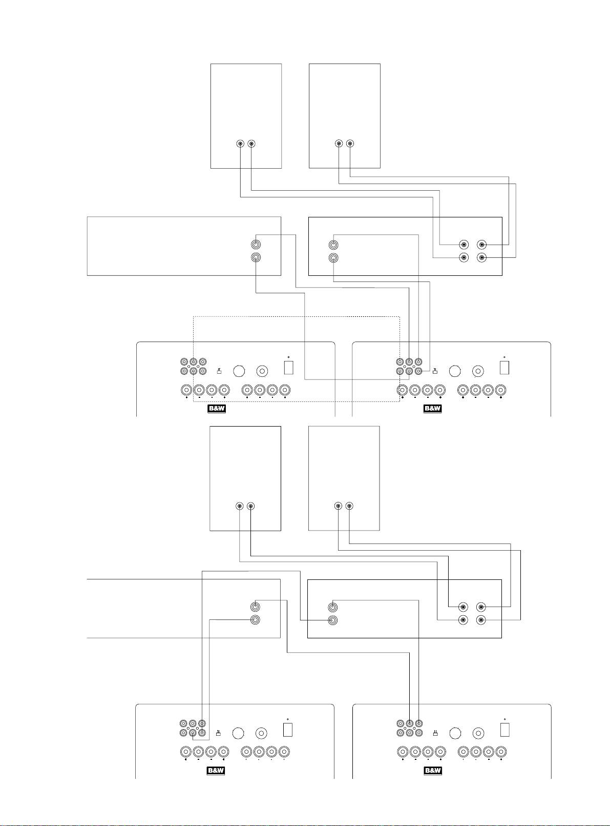
Figure 7
Figure 8
3
RIGHT
LEFT
-
++
-
LINE OUT
LINE IN
SPEAKERS OUT
R
L
L
L
+
R
R
-
Pre-Amplifier
Power Amplifier
LINK
OUT
LINE
IN
LINE
OUT
PHASE
LOW–PASS VOLUME
POWER
LINK
OUT
LINE
IN
LINE
OUT
PHASE
LOW–PASS VOLUME
POWER
L
60
ON
L
60
ON
50
70
50
70
AUTO
AUTO
R
0 180
80
R
0 180
80
100
OFF
100
OFF
14040
MIN MAX
14040
MIN MAX
TO SPEAKERS FROM AMPLIFIER
TO SPEAKERS FROM AMPLIFIER
RIGHT
LEFT
RIGHT LEFT
RIGHT
LEFT
RIGHT LEFT
ASW
™
2000
ASW
™
2000
ACTIVE SUBWOOFER
ACTIVE SUBWOOFER
No. 2
No. 1
RIGHT
LEFT
++
--
LINE OUT
LINE IN
SPEAKERS OUT
R
L
L
L
+
R
R
-
Pre-Amplifier
Power Amplifier
LINK
OUT
LINE
IN
LINE
OUT
PHASE
LOW–PASS VOLUME
POWER
LINK
OUT
LINE
IN
LINE
OUT
PHASE
LOW–PASS VOLUME
POWER
L
60
ON
L
60
ON
0 180
50
70
70
AUTO
R
80
R
0 180
50
80
AUTO
100
OFF
100
OFF
14040
MIN MAX
14040
MIN MAX
TO SPEAKERS FROM AMPLIFIER
TO SPEAKERS FROM AMPLIFIER
RIGHT
LEFT
RIGHT LEFT
RIGHT
LEFT
RIGHT LEFT
ASW
™
2000
ASW
™
2000
ACTIVE SUBWOOFER
ACTIVE SUBWOOFER
No. 2
No. 1
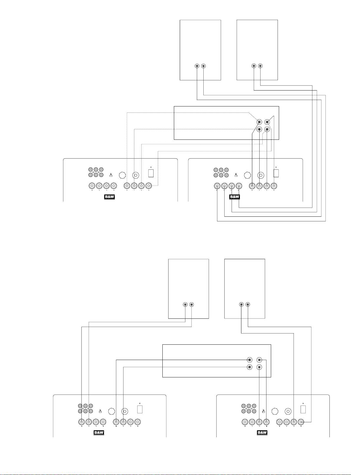
Figure 9
Figure 10
4
RIGHT
LEFT
-
++
-
SPEAKERS OUT
R
L
+
-
Integrated Amplifier
LINK
OUT
LINE
IN
LINE
OUT
PHASE
LOW–PASS VOLUME
POWER
LINK
OUT
LINE
IN
LINE
OUT
PHASE
LOW–PASS VOLUME
POWER
L
60
ON
L
60
ON
50
70
50
70
0 180
80
AUTO
AUTO
R
R
0 180
80
100
OFF
100
OFF
14040
MIN MAX
14040
MIN MAX
TO SPEAKERS FROM AMPLIFIER
TO SPEAKERS FROM AMPLIFIER
RIGHT
LEFT
RIGHT LEFT
RIGHT
LEFT
RIGHT LEFT
ASW
™
2000
ASW
™
2000
ACTIVE SUBWOOFER
ACTIVE SUBWOOFER
No. 2
No. 2
RIGHT
LEFT
-
++
-
SPEAKERS OUT
R
L
+
-
Integrated Amplifier
LINK
OUT
LINE
IN
LINE
OUT
PHASE
LOW–PASS VOLUME
POWER
LINK
OUT
LINE
IN
LINE
OUT
PHASE
LOW–PASS VOLUME
POWER
L
60
ON
L
60
ON
70
70
R
0 180
50
80
AUTO
R
0 180
50
80
AUTO
100
OFF
100
OFF
14040
MIN MAX
14040
MIN MAX
TO SPEAKERS FROM AMPLIFIER
TO SPEAKERS FROM AMPLIFIER
RIGHT
LEFT
RIGHT LEFT
RIGHT
LEFT
RIGHT LEFT
ASW
™
2000
ASW
™
2000
ACTIVE SUBWOOFER
ACTIVE SUBWOOFER
No. 2
No. 1
GB
8 Ventilation – The appliance should be
Safety Instructions
Warnings:
situated so that its location or position does
not interfere with its proper ventilation. For
To prevent fire or shock hazard, do not expose
example, the appliance should not be
this equipment to rain or moisture.
situated on a bed, sofa, rug, or similar
Observe all warnings on the equipment itself.
surface that may block the ventilation
To avoid electrical shock, do not open the
openings; or placed in a built-in installation,
enclosure or remove the amplifier from the
such as a bookcase or cabinet, that may
Caution:
rear panel. There are no user serviceable
impede the flow of air through the ventilation
parts inside. Refer all service questions to an
To reduce the risk of electric shock, do not
openings.
authorised B&W dealer.
remove the back panel. No user-serviceable
9 Heat – The appliance should be situated
parts inside. Refer servicing to qualified
To prevent electric shock, do not use this
away from heat sources such as radiators,
personnel.
(polarised) power plug with an extension cord
heat registers, stoves, or other appliances
receptacle or other outlet unless the blades can
that produce heat.
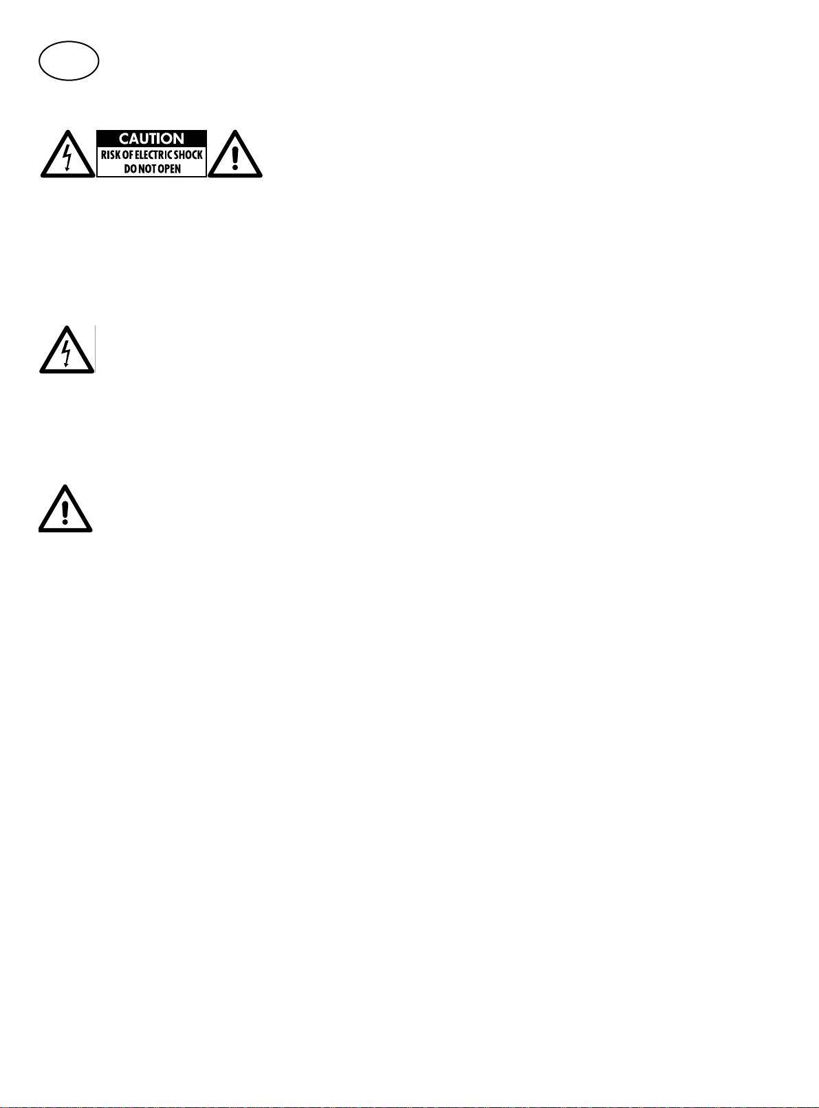
Explanation of Graphical Symbols
be fully inserted to prevent blade exposure.
10 Power Sources – The appliance should be
Ensure that the voltage indicated on the amplifier
connected to a power supply only of the
panel matches that of the power supply.
type described in the operating instructions
or as marked on the appliance.
The mains fuseholder is located on the back
panel of the amplifier module. Replacement fuse
11Grounding or Polarisation – The appliance
must be of the same type and rating as supplied.
is double insulated and should not be
The lightning flash within an equilateral triangle
grounded. When using an extension power-
The equipment should not be earthed (grounded)
is intended to alert you to the presence of unin-
supply cord or a power-supply cord other
To ensure adequate cooling of the amplifier,
sulated "dangerous voltage" within the product's
than that supplied with the appliance, it
operate the equipment only with the heatsink fins
enclosure that may be of sufficient magnitude to
should be 2-core, fitted with the appropriate
aligned vertically.
constitute an electric shock to persons.
moulded-on plugs and carry safety approval
appropriate to the country of use.
Important for UK only:
12 Power Cord Protection – Power-supply cords
The wires in this mains lead are coloured in
should be routed so that they are not likely to
accordance with the following code:
be walked on or pinched by items placed
on or against them, paying particular
blue: neutral
attention to cords at plugs, convenience
brown: live
The exclamation point within an equilateral
receptacles and the point where they exit
As the colours of the wires in the mains lead of
triangle is intended to alert you to the presence
from the appliance.
this apparatus may not correspond with the
of important operating and maintenance
13 Cleaning – The appliance should be
coloured markings identifying the terminals in
(servicing) instructions in the literature
cleaned only as recommended by the
your plug, proceed as follows:
accompanying the appliance.
manufacturer.
The terminal in the plug which is marked
14 Non-use Periods – Tthe power cord of the
with the letter E, or by the earth symbol, or
1 Read instructions – All the safety and
appliance should be unplugged from
coloured green or green and yellow must be
operating instructions should be read before
the outlet when left unused for a long
left unconnected.
the appliance is operated.
period of time.
The wire which is coloured blue must be
2 Retain instructions – The safety and operating
15 Object and Liquid Entry –- Care should be
connected to the terminal which is marked with
instructions should be retained for future
taken so that objects do not fall and liquids
the letter N or coloured black.
reference.
are not spilled into the enclosure through
The wire which is coloured brown must be
openings.
3 Heed warnings – All warnings on the
connected to the terminal which is marked with
appliance and in the operating instructions
16 Damage Requiring Service –- The appliance
the letter I or coloured red.
should be adhered to.
should be serviced by qualified personnel
The subwoofer is heavy and bulky, it should be
when:
4 Follow instructions – All operating and use
moved or lifted by at least two people.
instructions should be followed.
a The power-supply cord or the plug has
Check that there are no cables under the carpet
been damaged; or
5 Water and moisture – The appliance should
that may be damaged by the spikes.
b Objects have fallen, or liquid has been
not be used near water - for example, near
spilled into the appliance; or
Do not walk the unit on the spikes as this may
a bathtub, washbowl, kitchen sink, laundry
c The appliance has been exposed to rain; or
cause them to become detached from the
tub, in a wet basement, or near a swimming
d The appliance does not appear to operate
cabinet and cause damage.
pool and the like.
normally, or exhibits a marked change in
Take care not to spike through your own feet.
6 Carts and Stands – The appliance should be
performance; or
used only with a cart or stand that is
e The appliance has been dropped, or the
recommended by the manufacturer
enclosure damaged.
7 Wall or Ceiling Mounting – The appliance
17 Servicing – The user should not attempt to
should be mounted to a wall or ceiling only
service the appliance beyond that described
as recommended by the manufacturer.
in the operating instructions. All other
servicing should be referred to qualified
service personnel.
5

Introduction
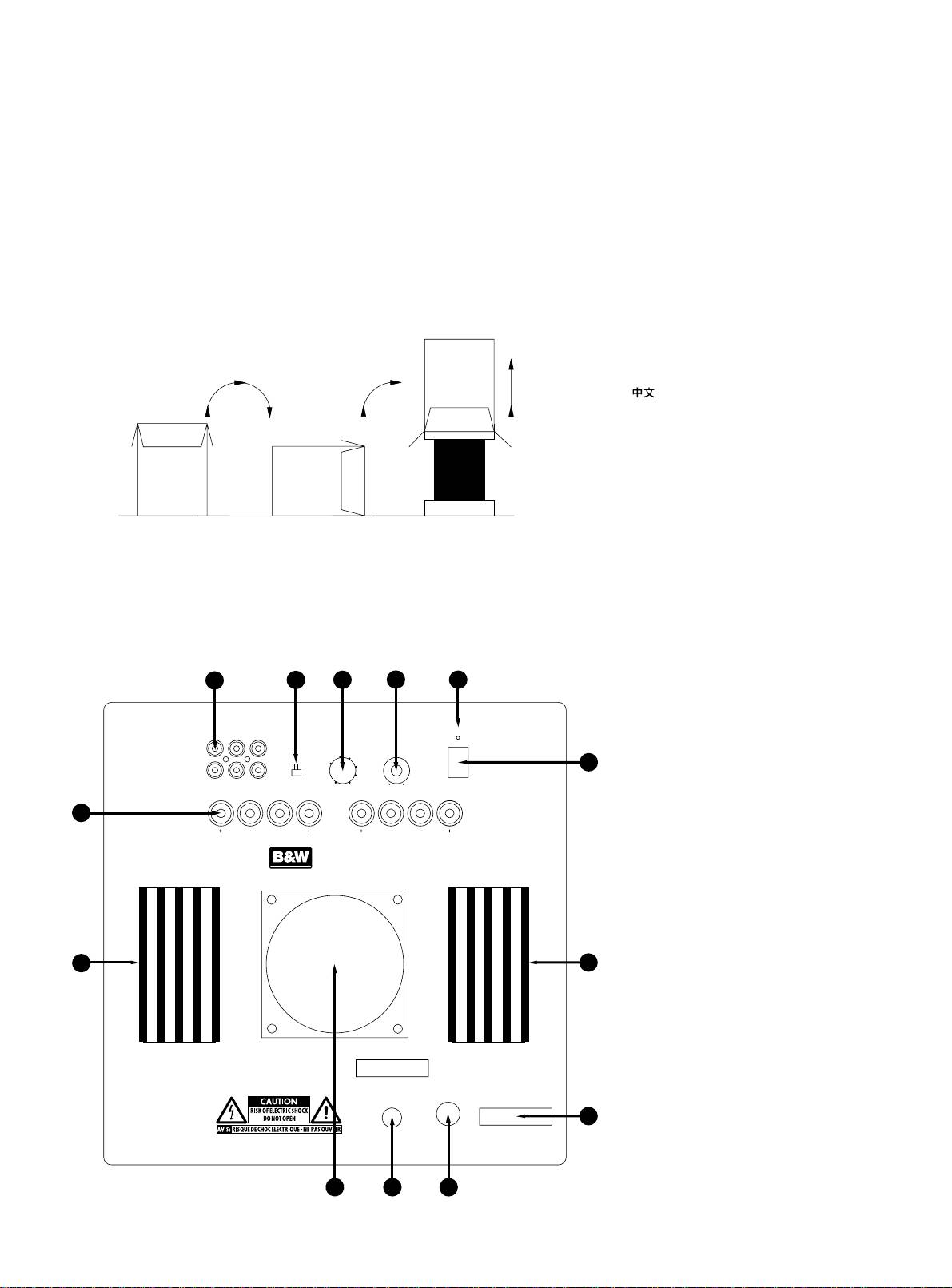
A tour of the subwoofer (figure 2)
Electrical connections
Thank you for purchasing the B&W ASW2000
Disconnect all sound system equipment from the
1 Heatsinks
Active Subwoofer.
power supply until the signal connections have
2 Line level connectors
been made and checked. This avoids the risk of
Since its foundation in 1966, the continuing
3 Speaker level connectors
damage whilst connections are made or broken.
philosophy of B&W has been the quest for
4 Low-pass filter frequency control
perfect sound reproduction. Inspired by the
5 Volume control
The function of the subwoofer is to receive
company’s founder, the late John Bowers, this
6 Phase switch
signals from the amplification chain and, where
quest has entailed not only high investment in
7 On/Auto/Off switch
necessary split the signal into low bass and
audio technology and innovation but also an
8 Power cord
higher frequencies and feed the latter back out
abiding appreciation of music and the demands
9 Voltage rating label
to the satellite speakers. Left and right channel
of film sound to ensure that the technology is put
10 Fuseholder
inputs may be combined into a single mono low
to maximum effect.
11 Power/Standby indicator
bass feed to the subwoofer drive unit if required.
12 Toroidal mains transformer housing
The ASW2000 has been designed for home
The subwoofer will input and output both line
theatre installations and to augment the bass
level signals via the RCA Phono sockets and
Positioning the subwoofer
performance of ‘full range’ speakers in stereo
speaker level signals via the 4mm binding posts
audio use. Adding the subwoofer to your
Because the subwoofer produces only low-
located on the back panel, giving a flexible
system not only extends the bass to lower
frequency sounds, positioning is less critical in
choice of connection methods. However, you
frequencies, it improves the midrange clarity
some respects compared to full-range speakers.
must not use a mixture of line level and speaker
by reducing the low-frequency demands on
Directional information is much less precise and
level connections in the same installation. If you
your existing speakers.
you have more choice where to place the
have a choice between line level and speaker
speakers to good effect. This said, best results
level connections, choose line level.
The subwoofer is magnetically shielded for use
are obtained if the subwoofer is placed between
close to a television screen.
Use the following table to select the correct
the satellite speakers or in the vicinity of one of
wiring method for your installation:
Please read through this manual fully before
them. If you use two subwoofers, it is best to put
using the subwoofer. All sound installations
one near each satellite speaker.
Application:
require some planning and experimentation if
Placing the subwoofer behind the listeners, even
you are to get the best out of the products used
in surround sound installations, generally gives
Home Theatre:- Equipment:
and this manual will guide you in this process.
inferior imaging; but may be an acceptable
• Decoder with separate power amplifiers:
As the subwoofer is connected to the electricity
compromise if domestic considerations dictate.
power supply, it is important that you familiarise
a With subwoofer output: Connections: fig. 3
As with all speakers, the proximity of room
yourself with the safety instructions and heed
b No subwoofer output: Connections: fig. 4
boundaries affects the sound. Bass is generally
all warnings.
increased as more surfaces come into close
•
Decoder with integrated power amplifiers:
Keep this manual in a safe place for future
proximity with the speakers. Unlike full-range
a With subwoofer output: Connections: fig. 5
reference.
speakers, however, you can always restore the
b No subwoofer output: Connections: fig. 6
correct overall system balance by adjusting the
B&W loudspeakers are distributed to over 50
volume level of the subwoofer. The more boost
countries world-wide and we maintain an
Application:
you get from the room, the less hard the speaker
international network of carefully chosen and
has to work; but there is a down side. Corner
dedicated distributors. If you have a problem
Stereo Audio:- Equipment:
positions often excite more low-frequency room
which your dealer cannot resolve, our distributors
resonances, making the bass more uneven with
• Separate pre- & power amplifiers:
will be more than willing to assist you.
frequency. There is no substitute for experiment
a One or more subwoofers with output
as all rooms behave differently, so try the
Unpacking (figure 1)
combined into a single mono signal:
subwoofer in a variety of positions before
Connections: fig. 7
The easiest way to unpack the subwoofer and
making a final decision. A piece of music with
b Two subwoofers with separate left and right
avoid damage is as follows:
a bass line ascending or descending the musical
signals: Connections: fig. 8
scale is useful for assessing the smoothness of
• Open the carton flaps right back and invert
the bass response. Listen for exaggerated or
• Integrated amplifier:
the carton and contents.
quiet notes. Having a separate subwoofer does
a One or more subwoofers with output
•
Lift the carton away from the product.
enable you to optimise for room resonances
combined into a single mono signal:
independently from siting the satellite speakers
•
We recommend that you retain the packaging
Connections: fig. 9
for best imaging.
for future use.
b Two subwoofers with separate left and
If the subwoofer is to be used in a confined
right signals: Connections: fig. 10
In addition to this manual, the carton
space (eg in custom furniture), the space must be
should contain:
ventilated to allow sufficient air to circulate and
Using more than one subwoofer
•
1 Subwoofer
cool the unit. Ask your dealer for advice.
• Using more than one unit in a single
•
1 Accessory pack containing:
The subwoofer is supplied with four spike feet.
installation can improve performance in the
•4 Spikes with lock nuts
The spikes pierce through carpet pile, giving a
following ways:
•
4 Self-adhesive rubber feet
firm support directly to the floor surface without
•Maintain stereo separation to the lowest
crushing the pile. When fitting spikes, first screw
frequencies.
the lock nuts fully onto the spikes, then screw the
spikes fully onto the threaded inserts in the base
•
Cope with larger listening rooms.
of the cabinet. If the unit rocks, loosen the
•
Enable greater maximum sound output – often
relevant two opposing spikes until the support is
useful for effectively reproducing special effects
firm, then re-tighten the lock nuts to the inserts. If
in Home Theatre applications. Smooth out the
the unit is to be placed on a vulnerable surface,
effects of low-frequency room resonances.
either place a protective disc under each spike
6
or fit the four rubber pads in place of the spikes.

If you are using two subwoofers for stereo audio,
• Set the VOLUME control to the half-way
At each setting of the cut-off frequency, listen with
stereo separation is improved if each channel
(12 o’clock) position (this is a standard THX
the phase switch in both positions. The correct
has its own subwoofer, providing each one is
pre-set level)
one is that which gives the fullest bass and that
sited close to the relevant satellite speaker.
will depend on the bass characteristics of your
• Set the PHASE switch initially to 0°, then see
satellite speakers and the relative distances of
If the subwoofers cannot be ideally sited, or if
the section below on fine tuning.
the subwoofer(s) and the satellite speakers to the
you are using a dedicated subwoofer output
Ensure that the subwoofer function on the THX
listeners. When using more than one subwoofer,
from a decoder, connect the second subwoofer
controller is enabled. When so configured it
ensure that each one has its cut-off frequency
from the first. If using a decoder, use only one
incorporates all the filtering and level setting
and phase switch set the same way.
input channel. For two channel audio, both input
required for the subwoofer in all modes. For level
channels should be used.
If at any time you make changes to the
calibration, the internal test noise and channel
amplification of the system such that you change
level controls in the THX controller should be
Double check the connections
from speaker to line level connections to the
used. In all cases the levels should be set so as
subwoofer, it is worth checking the phase setting
Before auditioning the sound quality of your new
to obtain 75db spl (C-weighted) at the listening
again, as the speaker level and line level
installation and fine tuning it, double check the
position from the controller’s internal noise test
high-pass filter phase characteristics of the
connections. All too often, users complain that
signal. Refer to your controller manual for further
subwoofer are different.
they cannot get a decent sound however they set
details as to how to set the levels. Inexpensive
the controls, only to discover something has been
sound level meters are readily available from
Set the loudness of the subwoofer relative to the
wrongly connected. Make sure that:
electronics stores and should be used to
satellite systems to your liking. Use a wide
calibrate the levels.
variety of programme material to get an average
• The phasing is correct – there should be no
setting. One that sounds impressive on one piece
positive to negative connections (this applies
Use with other home theatre decoders
may sound overpowering on another. Listen at
only to speaker level interconnects). If
realistic levels as the perception of balance
something is out of phase you may get a fuzzy
•
If the decoder has a dedicated subwoofer
varies with sound level.
sound with an imprecise and floating image,
output and an internal low-pass filter for the
a lack of bass or a combination of the two.
subwoofer having a slope of 2nd-order
If you get problems with lumpy bass – if certain
(12db/octave) or greater, set the LOW-PASS
bass notes are exaggerated more than others –
• There are no left to right mix-ups – this can
filter frequency to maximum, otherwise set it
then you probably have a room interface
result, for example, in the orchestra being the
initially to 80Hz.
problem and it is worth experimenting with the
wrong way round or, more disastrously, sounds
placement of the subwoofer. What may seem
on your home theatre going in the opposite
• Set the volume control initially to the half-way
like small changes in position – 15cm (6in) or
direction to the action on the screen.
(12 o’clock) position, then see the section
so – can have a profound effect on the sound.
below on fine tuning.
Try raising the subwoofer clear of the floor as
Switching on and off
•
Set the phase switch initially to 0°, then see
well as lateral movement. The use of multiple
We recommend that you switch the subwoofer
the section below on fine tuning.
subwoofers can smooth the effects of room
on before any power amplifiers receiving signals
resonances as each subwoofer will tend to excite
Use for stereo audio
from the subwoofer. Similarly, when switching
resonances at different frequencies. If you alter
off, switch the subwoofer off last.
• Set the LOW-PASS filter initially to 80hz then
the relative distances from the subwoofer(s)
see the section below on fine tuning.
and satellite speakers to the listeners
On first switching the subwoofer on, the amplifier
appreciably, reassess the phase switch setting.
goes into standby mode and the light above the
• Set the VOLUME control initially to the half way
You should also check the level setting of the
on/auto/off switch glows red. When an input
(12 o’clock) position, then see the section
subwoofer (using either the decoder output
signal is detected, the amplifier automatically
below on fine tuning.
levels or the volume control on the subwoofer
becomes fully active and the light glows green.
• Set the PHASE switch initially to 0°, then see
amplifier as appropriate), but only after setting
After a period of about 5 minutes without an
the section below on fine tuning.
the phase correctly.
input signal, the amplifier automatically reverts
to standby mode.
Fine tuning
Taking care of the subwoofer
The optimum settings of the PHASE switch and
The cabinet of the subwoofer may be cleaned
Setting the controls
the LOW-PASS filter frequency are inter-related
by dusting with a dry cloth. If you wish to use
There are three controls to consider:
and also dependent on the low-frequency
an aerosol cleaning spray, do not spray directly
cut-off characteristic of the satellite speakers
on the cabinet; spray onto the cloth. Remove
• The LOW-PASS filter frequency
and the relative positions of all the speakers
the grille first so that the cloth does not become
• The VOLUME control
in the installation.
stained, but be careful not to disturb the drive
unit. The grille itself may be cleaned using
• The PHASE switch
Set the system up in the preferred position and
a soft brush.
play some programme with a steady bass content.
The optimum settings depend on the other
The optimum setting for the LOW-PASS cut-off
Do not use the subwoofer as a table. When
equipment used with the subwoofer. If using
frequency depends on several variables the bass
in use, objects left on top of the subwoofer are
more than one subwoofer, make sure the controls
performance and power handling of the satellite
liable to rattle. In particular, avoid the risk of
on each one are set the same.
speakers, the number of subwoofers used and
liquids being spilled (eg from drinks or vases
®
Use with THX
controllers (including THX
their position relative to the satellite speakers.
of flowers).
controllers set in non-THX mode)
The range 80-90Hz is a good starting point
If the system is taken out of use for a long period,
for the LOW-PASS frequency. Unless two
The ASW2000 is not an THX licensed
disconnect the subwoofer from the power supply.
subwoofers are used to preserve separate right
component, but may be used with a THX
and left channel information and are sited close
controller if desired.
to the relevant satellite speakers, using a higher
• Set the LOW-PASS filter frequency to
cut-off frequency may compromise the stereo
maximum.
image and should only be considered if the
bass performance of the satellite speakers is
particularly limited.
7
