Karcher HDS 13/20-4 S *EU – page 2
Manual for Karcher HDS 13/20-4 S *EU

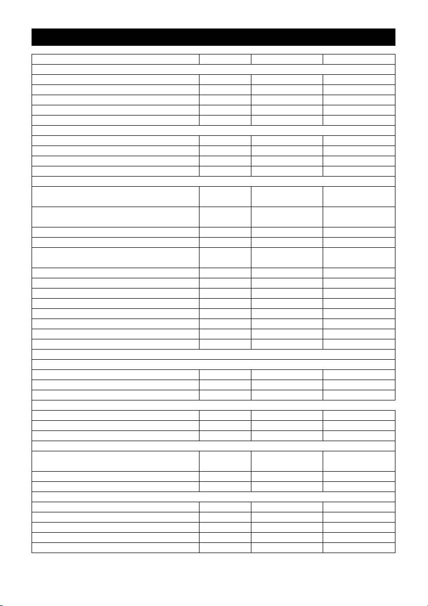
Wiederkehrende Prüfungen
Hinweis
Die Prüffristempfehlungen entsprechend der jeweiligen nationalen Anforderungen des Be-
treiberlandes sind zu beachten.
Prüfung durchge-
Äußere Prüfung Innere Prüfung Festigkeitsprü-
führt durch:
fung
Name Unterschrift der be-
Unterschrift der be-
Unterschrift der be-
fähigten Person/
fähigten Person/
fähigten Person/
Datum
Datum
Datum
Name Unterschrift der be-
Unterschrift der be-
Unterschrift der be-
fähigten Person/
fähigten Person/
fähigten Person/
Datum
Datum
Datum
Name Unterschrift der be-
Unterschrift der be-
Unterschrift der be-
fähigten Person/
fähigten Person/
fähigten Person/
Datum
Datum
Datum
Name Unterschrift der be-
Unterschrift der be-
Unterschrift der be-
fähigten Person/
fähigten Person/
fähigten Person/
Datum
Datum
Datum
Name Unterschrift der be-
Unterschrift der be-
Unterschrift der be-
fähigten Person/
fähigten Person/
fähigten Person/
Datum
Datum
Datum
Name Unterschrift der be-
Unterschrift der be-
Unterschrift der be-
fähigten Person/
fähigten Person/
fähigten Person/
Datum
Datum
Datum
– 15
21DE
Please read and comply with these
Environmental protection
original instructions prior to the ini-
tial operation of your appliance and store them
The packaging material can be
for later use or subsequent owners.
recycled. Please do not throw
– Before first start-up it is definitely nec-
the packaging material into
essary to read the operating instruc-
household waste; please send it
tions and safety indications Nr. 5.951-
for recycling.
949!
Old appliances contain valuable
– In case of transport damage inform ven-
materials that can be recycled;
dor immediately
these should be sent for recy-
– Check the contents of the pack before
cling. Batteries, oil, and similar
unpacking.
substances must not enter the
environment. Please dispose of
Contents
your old appliances using ap-
Environmental protection EN - 1
propriate collection systems.
Symbols in the operating in-
EN - 1
Please do not release engine oil, fuel oil,
structions
diesel and petrol into the environment
Overview EN - 2
Protect the ground and dispose of used
Symbols on the machine EN - 2
oil in an environmentally-clean manner.
Proper use EN - 2
Notes about the ingredients (REACH)
Safety instructions EN - 3
You will find current information about the
Safety Devices EN - 3
ingredients at:
Start up EN - 3
http://www.karcher.de/de/unternehmen/
Operation EN - 5
umweltschutz/REACH.htm
Storage EN - 9
Symbols in the operating in-
Transport EN - 9
structions
Maintenance and care EN - 9
Danger
Troubleshooting EN - 10
Immediate danger that can cause severe
Warranty EN - 12
injury or even death.
Accessories and Spare Parts EN - 12
몇 Warning
CE declaration EN - 13
Possible hazardous situation that could
Technical specifications EN - 14
lead to severe injury or even death.
Recurring tests EN - 15
Caution
Possible hazardous situation that could
lead to mild injury to persons or damage to
property.
22 EN
– 1
32 Oil drain screw
Overview
33 Backflow valve of the detergent infeed
34 Detergent suction hose 1 with filter
Device elements
35 Detergent suction hose 2 with filter
Figure 1
36 Fuel filter
1 Cover
37 Service switch
2 Support for spray lance
38 Water shortage safe guard with sieve
(both sides)
39 Swimmer tank
3 System care Advance RM 110/RM 111
40 Fine filter (water)
4 Guiding roll with fixed position brake
Operating field
5 Mounting location for transport
(both sides)
Figure 2
6 Folding compartment
A Power switch
(nur S)
B Temperature controller
7 High pressure connection
C Dosage valve for detergent
(nur S)
D Manometer
8 High pressure hose
E Display
9 Hand spraygun
Symbols on the machine
10 Spray lance
11 High-pressure nozzle (stainless steel)
High-pressure jets can be dan-
12 Steam nozzle (brass)
gerous if improperly used. The
jet may not be directed at per-
13 Power supply
sons, animals, live electrical equipment or
14 Safety latch of the hand spray gun
at the appliance itself.
15 Pressure/ quantity regulation at the
hand spray gun
Proper use
16 Connection for water supply with filter
Cleaning of: Machines, Vehicles, Struc-
17 Exit opening of the high-pressure hose
tures, Tools, Facades, Terraces, Garden-
(SX only)
ing tools, etc.
18 Step depression
Danger
19 Pouring vent for detergent 2
Risk of injury! Follow the respective safety
20 Hand crank for hose drum
regulations when operating at gas stations
(SX only)
or other dangerous areas.
21 Pouring vent for detergent 1
Please do not let mineral oil contaminat-
22 Hose drum
ed waste water reach soil, water or the
(SX only)
sewage system. Perform engine cleaning
23 Pouring vent for fuel
and bottom cleaning therefore only on
24 Handle
specified places with an oil trap.
25 Operating field
26 Closing flap for storage compartment
27 Storage compartment for accessories
28 Nameplate
29 Cover lock
30 Oil tank
31 Pressure/quantity regulation of the
pump unit
– 2
23EN

Safety instructions
Safety valve
– The safety valve opens, when the over-
– Please follow the national rules and regu-
lations for fuel spray jets of the respective
flow valve resp. the pressure switch is
country.
broken.
– Please follow the national rules and regu-
The safety valve is set by the manufacturer
lations for accident prevention of the re-
and sealed. Setting only by customer service.
spective country. Fuel spray jets must be
Water shortage safeguard
tested regularly and the results of these
tests must be documented in writing.
– The water shortage safeguard prevents
– The heating appliance of the machine is
the burner to be turned on when there is
an ignition plant. All national laws and
water shortage.
regulations about heating systems must
– A sieve prevents the contamination of
also be followed.
the safeguard and must be cleaned reg-
– As per the applicable national guidelines,
ulary.
the first time this high-pressure cleaner
must be taken into operation by a skilled
Temperature stop for exhaust gases
person. KÄRCHER has already per-
– The temperature stop switches off the
formed this initial start-up for you and has
documented it accordingly. The docu-
machine when the waste gases have
mentation can be requested at your
reached very high temperatures.
KÄRCHER partner. Please have the part
and plant number of the appliance availa-
Start up
ble when enquiring about the documenta-
tion.
몇 Warning
– We would like to point out that the appli-
Risk of injury! Device, tubes, high pressure
ance must be repeatedly checked by a
hose and connections must be in faultless
skilled person as prescribed by the appli-
condition. Otherwise, the appliance must
cable national regulations. Please con-
not be used.
tact your KÄRCHER partner.
Î Lock parking brake.
Safety Devices
Installing the handle
Safety devices serve for the protection of the
Figure 3
user and must not be put out of operation or
Caution
by passed with respect to their function.
Hook the electric supply line into the cable
Overflow valve with two pressure
guide of the right handle bow. Ensure that
switches
the cable is not damaged.
– While reducing the water supply at the
Replace the system care bottle
pump head or with the Servopress - reg-
ulation the overflow valve opens and part
Note: Push the bottle in securely to pene-
of the water flows back to the pump suck
trate the closure. Do not remove bottle until
side.
it is empty.
– If the hand-spray gun is closed, so that
Note: To protect the device, the burner is
the whole water flows back to the pump
switched off 5 hours after the system care
suck side, the pressure switch at the
bottle is empty.
overflow valve shuts down the pump.
– If the hand spray gun is opened, the pres-
– The system care prevents the calcifica-
sure switch on the cylinder head turns the
tion of the heating spiral while operating
pump back on.
with calciferous tap water. It is dosed
The overflow valve is set by the manufac-
into the supply in the float container
turer and sealed. Setting only by customer
drop by drop.
service.
24 EN
– 3

– The metering is set to medium water ri-
Refill detergent
gidity by the manufacturer
Note: A system care bottle is included in
Caution
the delivery.
Risk of injury!
Î Replace the system care bottle.
– Use Kärcher products only.
– Under no circumstances fill solvents
Adjusting the dosage of the system
(petrol, aceton, diluting agent etc.)
care Advance RM 110/RM 111
– Avoid eye and skin contact.
Î Determining the hardness of tap water:
– Observe safety and handling instruc-
– through the public water supply works,
tions by the detergent manufacturer.
– using a hardness tester (order no.
Kärcher offers an individual cleaning
6.768-004)
and care appliances program.
Your dealer will consult you gladly.
Water hard-
Scale on the service switch
Î Refill detergent.
ness (°dH)
<3 OFF (no dosing)
Install the hand-spray gun, the jet
3...7 1
pipe, the nozzle and the high pres-
7...14 2
sure hose
14...21 3
Figure 4
>21 4
Î Connect ray tube with hand spray gun
Î Set the service switch according to the
Î Tighten the screw connection of the
water hardness in the table.
spray lance fingertight.
Note: Observe the following when using
Î Insert high pressure nozzle into cover-
system care Advance 2 RM 111:
ing nut
– Calcification protection: See table
Î Install covering nut and tighten firmly
– Pump care and black water protection:
– Appliance without hose drum:
Set the service switch to at least setting 3.
Î Connect the high pressure host to the
high pressure connection point of the
Refill fuel
machine.
Danger
– Device with hose drum:
Risk of explosion! Only refill diesel oil or
Î Connect the high pressure hose to the
light fuel oil. Unsuitable fuels, e.g. petrol,
hand-spray gun.
are not to be used.
Caution
Caution
Always unwind high pressure hose completely
Never operate device with empty fuel tank
Installing the replacement high-
The fuel pump will otherwise be destroyed.
pressure hose (appliances without
Î Refill fuel.
hose drum)
Î Close tank lock.
Î Wipe off spilled fuel.
Figure 5
– 4
25EN

Until the pump sucked in water, you should:
Installing the replacement high-
Î Set the pressure/quantity regulation at
pressure hose (appliances with
the pump unit to maximum quantity.
hose drum)
Î Close the dosing valve for the detergent.
Figure 6
Danger
Î Completely roll off the high-pressure
Never suck in water from a drinking water
hose from the hose drum.
container. Never suck in liquids which con-
Î Rotate the hose drum until the screwed-
tain solvents like lacquer thinner, petrol, oil
on semibowl is pointing toward the top.
or unfiltered water. The sealings within the
Loosen all three screws and remove the
device are not solvent resistant. The spray
loosened semibowl.
mist of solvents is highly inflammable, ex-
Figure 7
plosive and poisonous.
Î Unlatch the fastening clamp for the high-
pressure hose and pull the hose out.
Power connection
Î Route the new high-pressure hose
– For connection values, see technical
through the intended hose guide and
data and type plate.
the deflection pulley at the bottom of the
appliance.
– The electrical connections must be
Î Slide the hose nipple all the way into the
done by an electrician according to IEC
knot section of the hose drum and se-
60364-1.
cure with the fastening clamp.
Danger
Î Replace the half bowl.
Danger of injury by electric shock.
Water connection
– Unsuitable extension cables can be
hazardous. Only use extension cables
For connection values refer to technical
outdoors which have been approved for
specifications
this purpose and labelled with a suffi-
Î Connect the supply hose (minimum
cient cable cross section:
length 7.5 m, minimum diameter 3/4“) to
– Always unwind extension lines com-
the water connection point of the ma-
pletely.
chine and at the water supply point (for
– The plug and coupling of the extension
e.g. a tap).
cable used must be watertight.
Note: The supply hose is not included.
Caution
suck in water from vessel
The maximum tolerable mains impedance
at the electrical contact point (see Techni-
If you want to suck in water from an exter-
cal Data) must not be exceeded.
nal vessel, the following modification is
necessary:
Operation
Figure 8
Danger
Î Remove water connection from the
pump head.
Risk of explosion!
Do not spray flammable liquids.
Î Unscrew the upper supply hose to the
swimmer container at the fine filter and
Danger
connect it to the pump head.
Risk of injury! Never use the appliance with-
Î Replug the rinse line of the detergent
out the spray lance attached. Check and en-
dosing valve.
sure proper fitting of the spray lance prior to
each use. The screw connection of the spray
Î Connect suction hose (minimum diame-
lance must be fingertight.
ter 3/4“) with filter (accessory) to the
Caution
water connection point.
Never operate device with empty fuel tank
– Max. suck height: 0.5 m
The fuel pump will otherwise be destroyed.
26 EN
– 5
Safety instructions
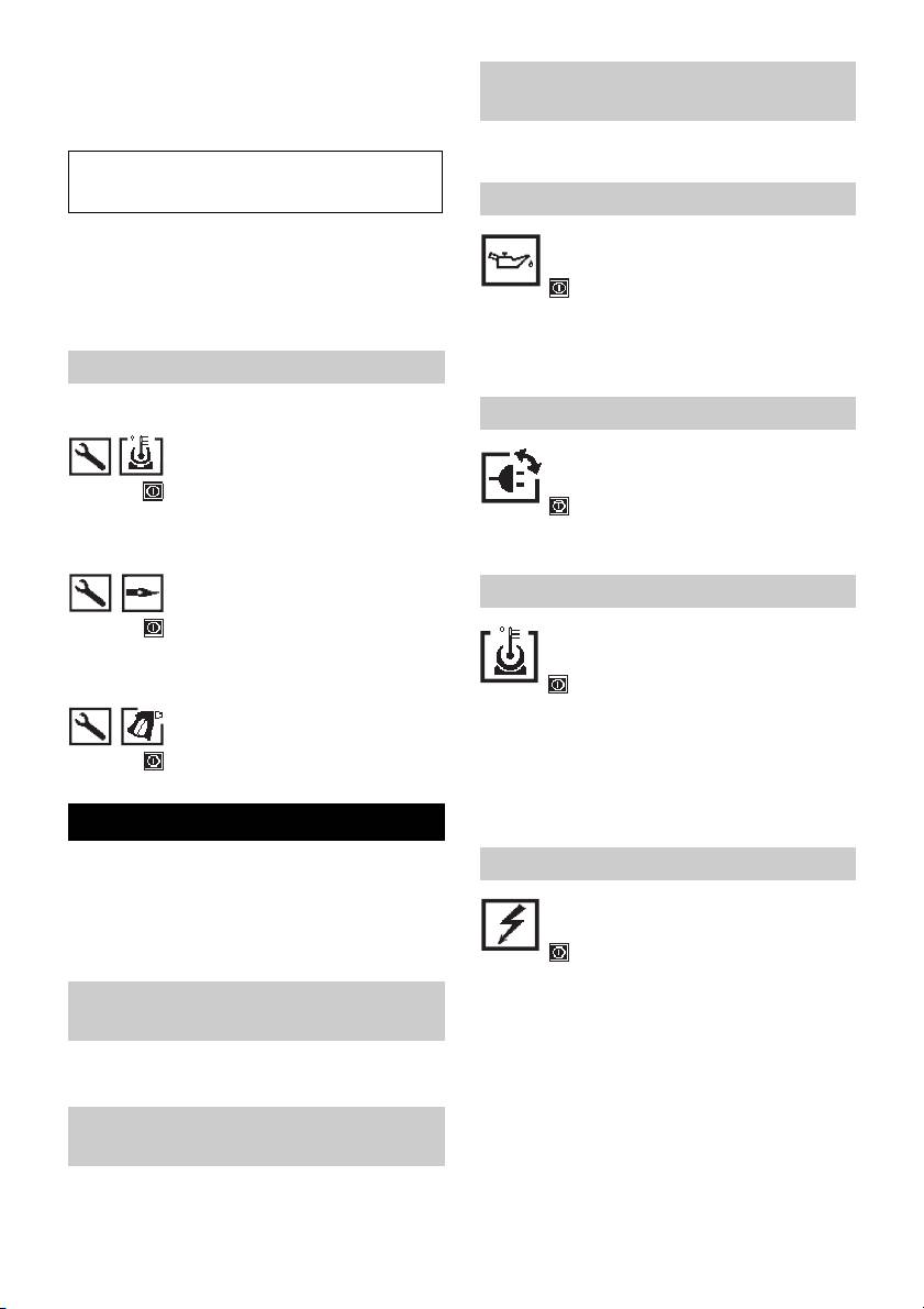
Operating modes
몇 Warning
Long hours of using the appliance can
cause circulation problems in the hands on
account of vibrations.
It is not possible to specify a generally valid
operation time, since this depends on sev-
eral factors:
– Proneness to blood circulation deficien-
cies (cold, numb fingers).
– Low ambient temperature. Wear warm
gloves to protect hands.
0/OFF =Off
– A firm grip impedes blood circulation.
1 Operating with cold water
– Continuous operation is worse than an
2 Eco operation (hot water max. 60 °C)
operation interrupted by pauses.
3 Operating with hot water/steam
In case of regular, long-term operation of
the device and in case of repeated occur-
Turning on the Appliance
rence of the symptoms (e.g. cold, numb fin-
Î Set appliance switch to desired operat-
gers) please consult a physician.
ing mode.
Replace the nozzle.
The device starts briefly and turns off, as
soon as the working pressure is reached.
Danger
Note: If the error symbol appears on the
Switch the appliance off prior to replacing
display during operation, immediately
nozzel and activate hand spray gun until
switch off the appliance and remove the er-
device is pressureless.
ror; see "Help for errors".
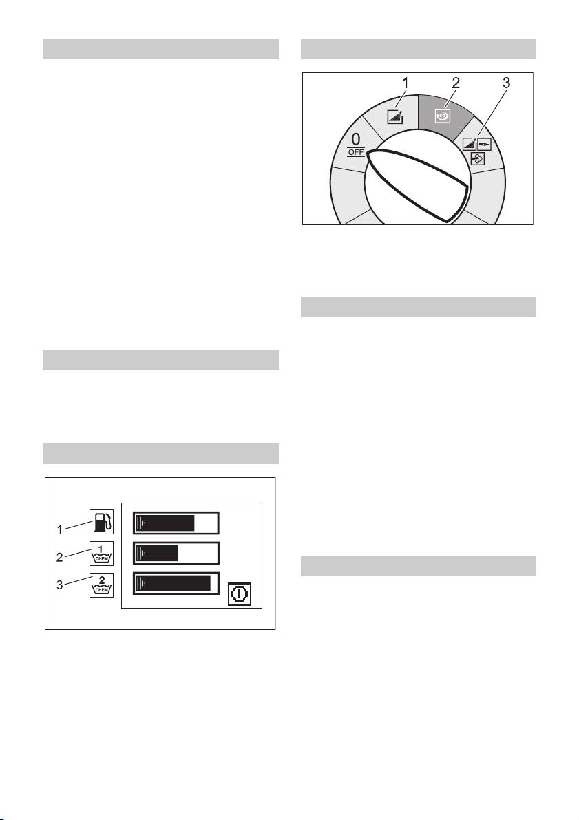
Display
Î Release the trigger gun.
When activating the hand spray gun the de-
vice switches back on.
Note:If no water comes out of the high
pressure nozzle, vent pump. Refer to "Help
with malfunctions - appliance is not building
up pressure".
Adjust cleaning temperature.
Î Set temperature regulator to desired
temperature.
30 °C to 95 °C
1 Bar graph - fuel fill level
– Clean with hot water.
2 Bar graph - detergent 1 fill level
100 °C to 150 °C
– Clean using steam.
3 Bar graph - detergent 2 fill level
– The operation and maintenance sym-
bols are displayed consecutively for 3
Follow the instructions given in the sec-
seconds each, just like in a slideshow.
tion "Operation with steam"!
– The error symbols remain until the ap-
pliance is switched off.
– 6
27EN

Set working pressure and flow rate
Recommended cleaning method
– Loosen the dirt:
Pressure/quantity regulation of the
Î Spray detergent economically and let it
pump unit
work for 1...5 minutes but do not let it
Î Turn the regulation spindle in a clock-
dry up.
wise direction: Increase working pres-
– Remove the dirt:
sure (MAX).
Î Spray off loosened dirt with the high-
Î Turn the regulation spindle in an anti-
pressure jet.
clockwise direction: Reduce working
Operating with cold water
pressure (MIN).
Pressure/ quantity regulation at the
Removal of light contaminations and clear
hand spray gun
rinse, i.e.: Gardening tools, terrace, tools, etc.
Î Set thermostat to max. 95 °C.
Î Set operating pressure according to
need.
Î Set the operating pressure on the pump
unit to the maximum value.
Eco operation
Î Set the working pressure and feed quan-
The appliance works in the most economi-
tity by turning (steplessly) the pressure/
cal temperature range.
quantity regulation mechanism at the
Note: The temperature can be regulated
hand spray gun (+/-).
up to 60 °C.
Danger
Operating with hot water/steam
When adjusting the pressure/quantity regu-
lation, make sure that the screw connection
We recommend the following cleaning tem-
of the spray lance does not become loose.
peratures:
Note: For long term work with low pres-
– Light contaminations
sure, set pressure at the pump unit.
30-50 °C
Operation with detergent
– Contaminations containing protein, i.e.
in the food processing industry
– For considerate treatment of the envi-
max. 60 °C
ronment use detergent economically.
– Vehicle cleaning, machine cleaning
– The detergent must be suitable for the
60-90 °C
surface to be cleaned.
– De-preserve, contaminations contain-
Î With support of the detergent dose
ing strong fat contents
valve set detergent concentration as
100-110 °C
determined by the manufacturer.
– De-frosting of surcharge substances,
Note: Recommended values at the control
partially facade cleaning
panel at maximum working pressure.
up to 140 °C
Cleaning
Operating with hot water
Î set pressure/temperature and deter-
Danger
gent concentration according to the sur-
Scalding danger!
face to be cleaned.
Î Set temperature regulator to desired
Note: To prevent damage due to too much
temperature.
pressure, always position high pressure ray
first from a greater distance towards object
to be cleaned.
28 EN
– 7

Operating with steam
Storing the Appliance
Danger
Î Lock in the steel pipe into the holder of
Scalding danger! The operating pressure
the appliance hood.
must not exceed 3,2 MPa (32 bar) when
Î Roll up high pressure hose and electri-
operating with temperatures above 98 °C.
cal conduit and hang them into the re-
Therefore the following measures must
spective holders.
definitely be performed:
Device with hose drum:
Î Before rolling up, stretch out the high
Î Replace high pressure nozzle (stain-
pressure hose.
less steel) with steam nozzle (brass,
Î Turn the hand crank clockwise (Direc-
order see specification).
tion of the arrow).
Î Open up the pressure/ quantity regula-
Note: Do not twist high pressure hose and
tor on the hand spray gun completely,
electrical conduit.
direction + until stop.
Frost protection
Î Set the operating pressure on the pump
unit to the minimum value.
Caution
Î Set temperature regulator to min. 100 °C.
Frost will destroy the not completely water
drained device.
After operation with detergent
Î Store in a frost free area.
Î Set dosing value for detergent to "0".
If the device is connected to a chimney, the
Î Set the appliance switch to "1" (opera-
following must be observed:
tion with cold water).
Caution
Î Open the hand spray gun and rinse the
Threat of damage by penetrating cold air
appliance for at least 1 minute.
through the chimney.
Turn off the appliance.
Î Disconnect device from chimney when
outside temperature drops below 0 °C.
Danger
If it is not possible to store frost free, shut
Danger of scalding by hot water. After the
down device.
operation with hot water or steam, the de-
Shutdown
vice must be operated with openend gun
with cold water for at least two minutes.
For longer work breaks or if a frost free stor-
Î Shut off water supply.
age is not possible:
Î Turn on pump shortly (appr. 5 seconds)
Î Drain water.
by activating the hand spray gun.
Î Flush device with anti-freeze agent.
Î Set the appliance switch to "0/OFF“.
Î Empty detergent tank.
Î Pull main plug out of socket with dry
Dump water
hands only.
Î Screw off water supply hose and high
Î Remove water connection.
pressure hose.
Î Activate hand spray gun until device is
Î Screw off supply hose at boiler bottom
pressure less.
and drain heating spiral empty.
Î Lock the trigger gun.
Î Operate device for max. 2 minutesuntil
the pump and lines are empty.
– 8
29EN

Flush device with anti-freeze agent
Maintenance intervals
Note: Observe handling instructions of the
anti-freeze agent manufacturer.
Weekly
Î Fill anti-freeze agent of the trade into
Î Clean the sieve in the water connection.
swimmer container.
Î Clean the fine filter.
Î Switch on appliance (without heater) till
Î Check oil level.
the appliance has been completely
Caution
rinsed.
In case of lacteous oil inform Kärcher cus-
A certain corrosion protection is achieved
tomer service immediately
with this as well.
Monthly
Storage
Î Clean sieve in the water shortage safe
guard.
Caution
Î Clean filter at the detergent suck hose.
Risk of injury and damage! Note the weight
After 500 operating hours, at least annually.
of the appliance in case of storage.
Î Oil change.
Transport
At least every 5 years, recurring
Figure 9
Î Perform the pressure test as per manu-
Caution
facturer's instructions.
Risk of damage! When loading the appli-
Maintenance Works
ance with a forklift, observe the illustration.
Clean the sieve in the water connection
Maintenance and care
Î Take out sieve.
Danger
Î Clean sieve in water and reinstall.
Risk of injury by inadvertent startup of ap-
Cleaning the fine filter
pliance and electrical shock.
Î Unpressurize the appliance.
First pull out the plug from the mains before
Î Unscrew lid with filter.
carrying out any tasks on the machine.
Î Clean the filter with clean water or com-
Î Shut off water supply.
pressed air.
Î Turn on pump shortly (appr. 5 seconds)
Î Reinstall in reverse sequence.
by activating the hand spray gun.
Clean sieve in the water shortage safe
Î Set the appliance switch to "0/OFF“.
guard
Î Pull main plug out of socket with dry
Î Unpressurize the appliance.
hands only.
Î Loosen covering nut and take off hose.
Î Remove water connection.
Î Take out sieve.
Î Activate hand spray gun until device is
Note: If necessary turn in screw M8 appr. 5
pressure less.
mm inwards and therewith pull out sieve.
Î Lock the trigger gun.
Î Clean sieve in water.
Î Allow device to cool down.
Î Push sieve inwards.
Your Kärcher vender will inform you
Î Put on hose.
about the performance of a periodic
Î Tighten covering nut firmly.
safety inspection resp. signing of a
maintenance contract.
Clean filter at the detergent suck hose
Î Take out detergent suck supports.
Î Clean filter in water and reinstall.
30 EN
– 9
Oil change.
Bar graph - detergent 2 fill level -
Î Ready a catch bin for appr. 1 Liter oil.
switches off
Î loosen release screw.
– Detergent tank 2 is empty.
Dispose of old oil ecologically or turn in at
Î Refill detergent.
a gathering point.
Pump symbol
Î Tighten release screw.
Î Fill oil slowly up to the MAX marking.
Note: Air pockets must be able to leak out.
For oil type refer to technical specifica-
– Lack of oil
tions.
Î Replenish oil.
Note: In case of lack of oil, the appliance
Maintenance work using the display
will not switch off.
Symbol pump maintenance
Rotation direction symbol
Î Perform maintenance procedure.
Figure 10
Symbol burner maintenance
Î
Exchange the poles at the appliance plug.
Engine symbol
Î Perform maintenance procedure.
Symbol accessory maintenance
– Engine overload/overheat
Î Set the appliance switch to "0/OFF“.
Î Allow device to cool down.
Î Perform maintenance procedure.
Î Turn on the appliance.
– Error occurs repeatedly.
Troubleshooting
Î Inform Customer Service
Danger
Electrical symbol
Risk of injury by inadvertent startup of ap-
pliance and electrical shock.
First pull out the plug from the mains before
carrying out any tasks on the machine.
– Contactor error
Bar graph - fuel fill level - switches
Î Set the appliance switch to "0/OFF“.
off
Î Turn on the appliance.
– Error occurs repeatedly.
– Fuel tank empty.
Î Inform Customer Service
Î Refill fuel.
– Fault in the voltage supply.
Bar graph - detergent 1 fill level -
Î Check main connections and mains fuse.
switches off
– Excessive power consumption.
– Detergent tank 1 is empty.
Î Check main connections and mains fuse.
Î Refill detergent.
Î Inform Customer Service
– 10
31EN
Water shortage symbol
System care symbol
– Water shortage
Note: Burner can operate 5 more hours.
Î Check water supply, check connections.
– System care bottle empty.
Î Replace the system care bottle.
Burner error symbol
Note: Burner operation no longer possible.
– The exhaust temperature limiter has
– System care bottle empty.
been triggered.
Î Replace the system care bottle.
Î Set the appliance switch to "0/OFF“.
Appliance is not running
Î Allow device to cool down.
Î Turn on the appliance.
– No power
– Error occurs repeatedly.
Î Check power connection/conduit.
Î Inform Customer Service
Device is not building up pressure
Error symbol
– Air within the system
Vent pump:
Î Set dosing value for detergent to "0".
Î With open hand spray gun turn device
on and off multiple times with the device
– Leak in the high pressure system
switch.
Î Check high pressure system and con-
Î Open and close the pressure/quantity
nections for tightness.
regulation at the pump unit with the
Î Inform Customer Service
hand spray gun open.
Flame sensor symbol
Note: By dismantling the high pressure
hose from the high pressure connection the
venting process is accelerated.
Î If detergent tank is empty, refill.
Î Check connections and conduits.
– The flame sensor turned the burner off.
– Pressure is set to MIN
Î Inform Customer Service
Î Set pressure to MAX.
System care detection symbol
– Sieve in the water connection is dirty
Î Clean sieve.
Î
Clean the fine filter; replace it, if necessary.
– Amount of water supply is too low.
Î Check water supply level (refer to tech-
– System care detection defective
nical data).
Î Inform Customer Service
32 EN
– 11

Device leaks, water drips from the
Set temperature is not achieved
bottom of the device.
while using hot water
– Pump leaky
– Working pressure/flow rate to high
Note: 3 drops/minute are allowed.
Î Reduce working pressure/flow quantity
Î With stronger leak, have device
at the pressure/volume regulator in the
checked by customer service.
pump unit.
– Sooty heating spiral
Device turns on and off while hand
Î Have device de-sooted by customer
spray gun is closed
service.
– Leak in the high pressure system
If malfunction can not be fixed, the de-
Î Check high pressure system and con-
vice must be checked by customer serv-
nections for tightness.
ice.
Device is not sucking in detergent
Warranty
Î Leave device running with open deter-
The warranty terms published by our com-
gent dosage valve and closed water sup-
petent sales company are applicable in
ply, until the swimmer tank is sucked
each country. We will repair potential fail-
empty and the pressure falls to "0".
ures of the appliance within the warranty
Î Open the water supply again.
period free of charge, provided that such
If the pump still is not sucking in any deter-
failure is caused by faulty material or de-
gent, it could be because of the following
fects in fabrication.
reasons:
Accessories and Spare Parts
– Filter in the detergent suck hose dirty
Î Clean filter.
– Only use accessories and spare parts
– Backflow valve stuck
which have been approved by the man-
ufacturer. The exclusive use of original
Î Remove the detergent hose and loosen
accessories and original spare parts
the backflow valve using a blunt object.
ensures that the appliance can be oper-
Burner does not start
ated safely and troublefree.
– System care bottle empty.
– At the end of the operating instructions
you will find a selected list of spare parts
Î Replace the system care bottle.
that are often required.
– Fuel tank empty.
– For additional information about spare
Î Refill fuel.
parts, please go to the Service section
– Water shortage
at www.kaercher.com.
Î Check water supply, check connections.
Î Clean sieve in the water shortage safe
guard.
– Fuel filter dirty
Î Change fuel filter.
– No ignition spark
Î If device is in use and no ignition spark
can be seen through the viewing glas,
have device checked by customer serv-
ice.
– 12
33EN

ID No. 0035
CE declaration
Sound power level dB(A)
We hereby declare that the machine de-
Measured: 89
scribed below complies with the relevant
Guaranteed: 91
basic safety and health requirements of the
EU Directives, both in its basic design and
5.957-902
construction as well as in the version put
into circulation by us. This declaration shall
The undersigned act on behalf and under
cease to be valid if the machine is modified
the power of attorney of the company man-
without our prior approval.
agement.
Product: High-pressure cleaner
Type: 1.071-xxx
Relevant EU Directives
CEO
Head of Approbation
97/23/EC
2006/42/EC (+2009/127/EC)
Alfred Kärcher GmbH Co. KG
2004/108/EC
Alfred-Kärcher-Str. 28 - 40
1999/5/EC
71364 Winnenden (Germany)
2000/14/EC
Applied conformity evaluation method
Phone: +49 7195 14-0
for 2000/14/EC
Fax: +49 7195 14-2212
Appendix V
Component category
II
Conformity procedure
Module H
Heating coil
Conformity assessment Module H
Safety valve
Conformity assessment Art. 3 para 3
control block
Conformity assessment Module H
various pipes
Conformity assessment Art. 3 para 3
Applied harmonized standards
EN 55014–1: 2006
EN 55014–2: 1997 + A1: 2001
EN 60335–1
EN 60335–2–79
EN 61000–3–2: 2006
EN 61000–3–3: 2008
EN 61000–3–11: 2000
EN 62233: 2008
EN 300 330-2 V1.3.1 : 2006
EN 301 489-1 V1.6.1 : 2005
EN 301 489-3 V1.4.1 : 2002
Applied specifications:
Based on AD 2000
Based on TRD 801
Name of the appointed agency:
for 97/23/EG
TÜV Rheinland Industrie Service GmbH
Am Grauen Stein
51105 Köln
34 EN
– 13
Technical specifications
HDS 13/20 HDS 13/20
Main Supply
Voltage V 230 400
Current type Hz 3~ 50 3~ 50
Connected load kW 9,3 9,3
Protection (slow) A 55 32
Maximum allowed net impedance Ohm (0.159+j0.100) (0.159+j0.100)
Water connection
Max. feed temperature °C 30 30
Min. feed volume l/h (l/min) 1500 (25) 1500 (25)
Suck height from open container (20 °C) m 0,5 0,5
Max. feed pressure MPa (bar) 1 (10) 1 (10)
Performance data
Water flow rate l/h (l/min) 600-1300 (10-
600-1300 (10-
21,6)
21,6)
Operating pressure of water (using standard
MPa (bar) 3-20 (30-200) 3-20 (30-200)
nozzle)
Max. excess operating pressure (safety valve) MPa (bar) 24 (240) 24 (240)
Steam flow rate l/h (l/min) 600-670 (10-11,1) 600-670 (10-11,1)
Max. operating pressure for working with
MPa (bar) 3,2 (32) 3,2 (32)
steam (using steam nozzle)
Part no. of steam nozzle -- 2.885-044.0 2.885-044.0
Max. operating temperature of hot water °C 95 95
Working temperature steam operation °C 155 155
Detergent suck in l/h (l/min) 0-78 (0-1,3) 0-78 (0-1,3)
Burner performance kW 108 108
Maximum consumption of heating oil kg/h 8,3 8,3
Max. recoil force of hand spray gun N 40,3 40,3
Nozzle size -- 070 070
Values determined as per EN 60355-2-79
Noise emission
Sound pressure level L
pA
dB(A) 74 74
Uncertainty K
pA
dB(A) 2 2
Sound power level L
WA
+ Uncertainty K
WA
dB(A) 91 91
Hand-arm vibration value
2
Hand spraygun m/s
1,66 1,66
2
Spray lance m/s
5,85 5,85
2
Uncertainty K m/s
1,0 1,0
Fuel
Fuel -- Fuel oil EL or Die-
Fuel oil EL or Die-
sel
sel
Amount of oil l 1,0 1,0
Oil grade -- SAE 90 SAE 90
Dimensions and weights
Length x width x height mm 1330 x 750 x 1060 1330 x 750 x 1060
Weight without accessories (S) kg 186 186
Weight without accessories (SX) kg 194 194
Fuel tank l 25 25
Detergent Tank l 10+20 10+20
– 14
35EN

Recurring tests
Note
The recommended testing frequencies of the respective statutory regulations of the country
of operation are to be followed.
Testing done by: External testing Internal testing Leak-proof tests
Name Signature of the
Signature of the
Signature of the
authorised person/
authorised person/
authorised person/
date
date
date
Name Signature of the
Signature of the
Signature of the
authorised person/
authorised person/
authorised person/
date
date
date
Name Signature of the
Signature of the
Signature of the
authorised person/
authorised person/
authorised person/
date
date
date
Name Signature of the
Signature of the
Signature of the
authorised person/
authorised person/
authorised person/
date
date
date
Name Signature of the
Signature of the
Signature of the
authorised person/
authorised person/
authorised person/
date
date
date
Name Signature of the
Signature of the
Signature of the
authorised person/
authorised person/
authorised person/
date
date
date
36 EN
– 15
Lire ces notice originale avant la
Protection de l’environne-
première utilisation de votre appa-
ment
reil, se comporter selon ce qu'elles requièrent
et les conserver pour une utilisation ultérieure
Les matériaux constitutifs de
ou pour le propriétaire futur.
l’emballage sont recyclables.
– Avant la première mise en service, vous
Ne pas jeter les emballages
devez impérativement avoir lu les con-
dans les ordures ménagères,
signes de sécurité N° 5.951-949 !
mais les remettre à un système
– Contactez immédiatement le revendeur
de recyclage.
en cas d'avarie de transport.
Les appareils usés contiennent
– Vérifier le contenu du paquet lors de
des matériaux précieux recycla-
l'ouverture de l'emballage.
bles lesquels doivent être appor-
tés à un système de recyclage. Il
Table des matières
est interdit de jeter les batteries,
l'huile et les substances similai-
Protection de l’environnement FR - 1
res dans l'environnement. Pour
Symboles utilisés dans le
FR - 1
cette raison, utiliser des systè-
mode d'emploi
mes de collecte adéquats afin
Aperçu général FR - 2
d'éliminer les appareils hors
d'usage.
Symboles sur l'appareil FR - 2
Utilisation conforme FR - 2
Ne jetez pas l'huile moteur, le fuel, le die-
Consignes de sécurité FR - 3
sel ou l'essence dans la nature. Protéger
le sol et évacuer l'huile usée de façon fa-
Dispositifs de sécurité FR - 3
vorable à l'environnement.
Mise en service FR - 4
Utilisation FR - 6
Instructions relatives aux ingrédients
Entreposage FR - 10
(REACH)
Les informations actuelles relatives aux in-
Transport FR - 10
grédients se trouvent sous :
Entretien et maintenance FR - 10
http://www.karcher.de/de/unternehmen/
Assistance en cas de panne FR - 11
umweltschutz/REACH.htm
Garantie FR - 14
Symboles utilisés dans le
Accessoires et pièces de re-
FR - 14
mode d'emploi
change
Déclaration CE FR - 14
Danger
Caractéristiques techniques FR - 15
Pour un danger immédiat qui peut avoir
Essais périodiques FR - 16
pour conséquence la mort ou des blessu-
res corporelles graves.
몇 Avertissement
Pour une situation potentiellement dange-
reuse qui peut avoir pour conséquence des
blessures corporelles graves ou la mort.
Attention
Pour une situation potentiellement dange-
reuse qui peut avoir pour conséquence des
blessures légères ou des dommages maté-
riels.
– 1
37FR
29 Fermeture du capot
Aperçu général
30 Réservoir d'huile
31 Réglage de la pression/ du débit de
Éléments de l'appareil
l'unité de pompe
Figure 1
32 Bouchon de vidange d'huile
1 Capot
33 Soupape anti-retour de l'aspiration de
2 Dispositif de fixation de la lance
détergent
(bilatéral)
34 Flexible d'aspiration du détergent 1
3 Entretien système Advance RM 110/
avec filtre
RM 111
35 Flexible d'aspiration du détergent 2
4 Roulettes pivotantes et frein de station-
avec filtre
nement
36 Filtre de combustible
5 Point de fixation pour le transport
37 Commutateur de service
(bilatéral)
38 Protection contre le manque d'eau avec
6 Compartiment pliant
tamis
(uniquement S)
39 Réservoir flottant
7 Raccord haute pression
40 Filtre fin (eau)
(uniquement S)
Zone de commande
8 Flexible haute pression
9 Poignée-pistolet
Figure 2
A Interrupteur principal
10 Lance
B Thermostat
11 Buse haute pression (acier inoxydable)
C Vanne de dosage du détergent
12 Buse de vapeur (laiton)
D Manomètre
13 Alimentation électrique
EEcran
14 Cran de sécurité de la poignée-pistolet
15 Réglage de la pression/ du débit à la
Symboles sur l'appareil
poignée-pistolet.
Une utilisation incorrecte des
16 Arrivée d'eau avec tamis
jets haute pression peut présen-
17 Ouverture de sortie du flexible haute
ter des dangers. Le jet ne doit
pression
pas être dirigé sur des personnes, ani-
(uniquement SX)
maux, installations électriques actives ni
18 Cavité de marche
sur l'appareil lui-même.
19 Orifice de remplissage pour détergent 2
20 Manivelle pour dévidoir
Utilisation conforme
(uniquement SX)
Nettoyage de : machines, véhicules, bâti-
21 Orifice de remplissage pour détergent 1
ments, outils, façades, terrasses, appareils
22 Dévidoir
de jardinage, etc.
(uniquement SX)
Danger
23 Orifice de remplissage pour combustible
Risque de blessure ! En cas d'utilisation
24 Poignée
dans l'enceinte d'une station service ou
25 Pupitre de commande
dans d'autres zones à risque, respecter les
26 Capot du compartiment de rangement
consignes de sécurité correspondantes.
27 Compartiment de rangement pour ac-
cessoires
28 Plaque signalétique
38 FR
– 2

Ne pas évacuer les eaux usées conte-
Clapet de décharge doté de deux
nant de l'huile minérale dans la terre, les
pressostats
dispositifs pour eaux usées ou les canali-
– En cas de réduction du débit d'eau au
sations. Dès lors, effectuer le nettoyage
niveau de la tête de la pompe ou avec
du moteur ou du bas de caisse unique-
le réglage de la servopresse, la clapet
ment aux postes de lavage appropriés et
de décharge s'ouvre et une partie de
équipés d'un séparateur d'huile.
l'eau est évacuée vers le côté aspiration
de la pompe.
Consignes de sécurité
– Si la poignée-pistolet est fermés, de
– Respecter les dispositions légales na-
sorte que toute l'eau retourne vers le
tionales respectives pour les jets de li-
côté aspiration de la pompe, le pressos-
quide.
tat du clapet de décharge désactive la
pompe.
– Respecter les dispositions légales na-
tionales respectives pour la prévention
– Si la poignée-pistolet est de nouveau
des accidents. Les jets de liquides doi-
ouverte, le pressostat de la culasse
vent être contrôlés régulièrement et le
réactive la pompe.
résultat du contrôle consigné par écrit.
Le clapet de décharge est réglé et plombé
– Le dispositif de chauffage de l'appareil
d'usine. Seul le service après-vente est
est une installation de combustion. Les
autorisé à effectuer le réglage.
installations d'allumage doivent être
contrôlées régulièrement en concor-
Soupape de sûreté
dance avec les dispositions légales na-
– La soupape de sûreté s'ouvre lorsque le
tionales respectives.
clapet de décharge ou le pressostat est
– Selon les dispositions nationales en vi-
défectueux.
gueur, ce nettoyeur haute pression doit
être mis en service la première fois par
La soupape de sûreté est réglée et plom-
une personne compétente en cas d'uti-
bée d'usine. Seul le service après-vente est
lisation professionnelle. KÄRCHER a
autorisé à effectuer le réglage.
déjà exécuté et documenté cette pre-
Dispositif de sécurité en cas de
mière mise en service pour vous. La do-
cumentation à ce sujet vous sera
manque d'eau
remise par le biais de votre Partenaire
– Le dispositif de sécurité en cas de man-
KÄRCHER sur demande. Veuillez
que d'eau permet d'éviter que le brûleur
maintenir le numéro de pièce et le nu-
se mette en marche lorsque la quantité
méro d'usine de l'appareil prêt en cas
demande pour la documentation.
d'eau est insuffisante.
– Nous attirons votre attention sur le fait
– Un tamis protège le dispositif de sécuri-
que l'appareil doit être contrôlé réguliè-
té contre les impuretés. Il doit être net-
rement par une personne compétente
toyé régulièrement.
selon les dispositions nationales en vi-
gueur. Adressez-vous pour cela à votre
Limiteur de la température de tuyère
partenaire KÄRCHER.
– Le limiteur de la tempérautre de tuyère
Dispositifs de sécurité
arrête l'appareil en attendant une tem-
pérautre très haute de tuyère.
Les dispositifs de sécurité ont pour but de
protéger l'utilisateur. Par conséquent, ils ne
doivent en aucun cas être désactivés ou
transformés.
– 3
39FR

Dureté d'eau
Echelle sur le commutateur
Mise en service
(°dH)
de service
몇 Avertissement
<3 OFF (pas de dosage)
Risque de blessure ! L'appareil, les condui-
3...7 1
tes d'alimentation, les flexibles haute pres-
7...14 2
sion et les raccords ne doivent présenter
14...21 3
aucun défaut. Ne pas utiliser l'appareil si
>21 4
son état n'est pas irréprochable.
Î Serrer le frein de stationnement.
Î Régler le commutateur de service selon
le tableau en fonction de la dureté de
Monter la poignée
l'eau.
Figure 3
Remarque : Respecter ce qui suit lors de
l'utilisation du soin système Advance 2
Attention
RM 111 :
Accrocher l'alimentation électrique dans le
– Protection contre l'entartrage : voir le ta-
guide de câble de l'étrier de poignée droit.
bleau
Faire attention que le câble ne soit pas en-
– Soin des pompes et protection contre
dommagé.
l'eau noire : régler le commutateur de
Remplacer la bouteille d'entretien
service au moins sur la position 3.
système
Remplissage du combustible
Remarque : Presser fortement la bouteille
lors de la mise en place afin de traverser la
Danger
fermeture. Ne pas retirer la bouteille avant
Risque d'explosion ! N'utiliser que du car-
qu'elle ne soit vide.
burant diesel ou du fuel léger. Il est interdit
Remarque : Pour la protection de l'appa-
d'utiliser des combustibles non appropriés,
reil, le brûleur est mis hors service avec
tels que l'essence.
une temporisation de 5 heures quand la
Attention
bouteille d'entretien système est vide.
Ne jamais utiliser l'appareil lorsque le ré-
– L'entretien système enraye l'entartrage
servoir à combustible est vide sous peine
du serpentin de chauffage avec une for-
d'endommager la pompe à combustible.
te efficacité en cas d'utilisation d'eau du
Î Remplissage du combustible.
robinet calcaire. Il est ajouté goutte-à-
Î Fermer le couvercle du réservoir.
goutte à l'alimentation dans le réservoir
Î Essuyer le combustible ayant éventuel-
à flotteur.
lement débordé.
– Le dosage est effectué d'usine pour ob-
tenir une dureté d'eau moyenne.
Faire le plein de détergent
Remarque :Le contenu de la livraison com-
Attention
porte une bouteille d'entretien système.
Risque de blessure !
Î Remplacer la bouteille d'entretien sys-
– Utiliser uniquement les produits Kär-
tème.
cher.
Régler le dosage de l'entretien sys-
– N'utiliser en aucun cas de solvant (es-
tème Advance RM 110/RM 111.
sence, acétone, diluant, etc.).
– Eviter tout contact avec les yeux ou la
Î Déterminer la dureté de l'eau locale :
peau.
– En contactant le distributeur local,
– Respecter les consignes de sécurité et
– avec un appareil pour essai de dureté
d'utilisation fournies par le fabricant du
(N° de commande 6.768-004).
détergent.
40 FR
– 4


