Milwaukee MDE 38 Compact: инструкция
Раздел: Электроинструменты
Тип:
Инструкция к Milwaukee MDE 38 Compact
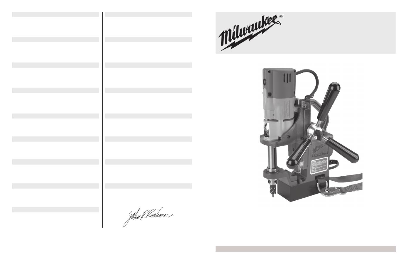
MDE 38 Compact
ATLAS COPCO ELECTRIC TOOLS
Winnenden Germany
58-13-4270d1 08/02 Printed in USA
ÅëëçíéêÜ
ÄÞëùóç åíáñìüíéóçò ìå ÅÅ
Äçëþíïõìå õðåõèýíùò üôé ôá ðáñüíôá ðñïúüíôá åßíáé óýìöùíá ìå ôá ðáñáêÜôù
ðñüôõðá êáé ôõðïðïéçìÝíá Ýããñáöá. EN 55 014, EN 61 000, EN 61 029, EN
60 555, IEC 61 029 óýìöùíá ìå ôïõò êáíïíéóìïýò 73/23/ÅÏÊ, 89/336/ÅÏÊ,
93/68/EOK êá é 98/37/EK.
Deutsch
CE-Konformitätserklärung
Wir erklären auf eigene Verantwortung, daß diese Produkte im Einklang mit
73/23/EEC, 89/336/EEC, 93/68/EEC und 98/37/EG den folgenden Normen
oder Normunterlagen entsprechen: EN 55 014, EN 61 000, EN 61 029, EN
60 555, IEC 61 029.
Français
Déclaration de conformité CEE
Nous déclarons sous notre seule responsabilité que ce produit est conforme
aux normes et documents normatifs EN 55 014, EN 61 000, EN 61 029, EN
60 555, IEC 61 029 et satisfait aux réglementations 73/23/EEC, 89/336/
EEC, 93/68/EEC et 98/37/CE.
Suomi
CE:-vaatimustenmukaisuusvakuutus
Ilmoitamme täten täysin omalla vastuullamme, että nämä tuotteet ovat
yhdenmukaisia seuraavien standardien tai standardiasiakirjojen kanssa: EN
55 014, EN 61 000, EN 61 029, EN 60 555, IEC 61 029 säädösten 73/23/ETY,
89/336/ETY, 93/68/ETY ja 98/37/EY mukaisesti.
Nederlands
CE conformiteitsverklaring
Wij verklaren onder onze eigen, exclusieve verantwoording dat deze
producten conform zijn met de volgende normen en normatieve documenten:
EN 55 014, EN 61 000, EN 61 029, EN 60 555, IEC 61 029 in overeenstemming
met de reglementen 73/23/EEC, 89/336/EEC, 93/68/EEC en 98/37/EG.
Dansk
EU-overensstemmelseserklæring
Vi erklærer under eneansvar, at disse produkter er i overensstemmelse med
følgende standarder eller standardiserede dokumenter. EN 55 014,
EN 61 000, EN 61 029, EN 60 555, IEC 61 029 i overensstemmelse med
regulativ 73/23/EEC, 89/336/EEC, 93/68/EEC og 98/37/EF.
English
CE Declaration of Conformity
We declare under our sole responsibility that these products are in confor-
mity with the following standards or standardized documents.
EN 55 014, EN 61 000, EN 61 029, EN 60 555, IEC 61 029 in accordance
with the regulations 73/23/EEC, 89/336/EEC, 93/68/EEC and 98/37/EC.
Italiano
Dichiarazione di conformità CE
La
MILWAUKEE tools dichiara sotto la propria assoluta responsabilità che
questi prodotti sono conformi alle seguenti normative o documenti unificati:
EN 55 014, EN 61 000, EN 61 029, EN 60 555, IEC 61 029 secondo le
normative 73/23/CEE, 89/336/CEE, 93/68/CEE e 98/37/CE.
Norsk
CE Erklœring om konformitet
Vi erklærer at vi står alene om ansvaret for at disse produktene er i
overensstemmelse med følgende standarder eller standardiserte documenter.
EN 55 014, EN 61 000, EN 61 029, EN 60 555, IEC 61 029 I henhold til
vedtektene 73/23/EEC, 89/336/EEC, 93/68/EEC og 98/37/EF.
Português
Declaração de Conformidade da CE
Declaramos sob nossa única responsabilidade que estes produtos estão em
conformidade com as seguintes normas ou documentos normalizados: EN
55 014, EN 61 000, EN 61 029, EN 60 555, IEC 61 029 de acordo com os
regulamentos 73/23/CEE, 89/336/CEE, 93/68/CEE e 98/37/CE.
Español
Declaración de conformidad de la CE
Declaramos bajo nuestra propia responsabilidad que estos productos cumplen
con las siguientes normas o documentos de normalización: EN 55 014, EN
61 000, EN 61 029, EN 60 555, IEC 61 029 de conformidad con las
Reglamentaciones 73/23/EEC, 89/336/EEC, 93/68/EEC y 98/37/CE.
Svenska
CE Konformitetsdeklaration
Vi intygar och är ensamma ansvariga för att dessa produkter uppfyller följande
standarder eller normgivande dokument. EN 55 014, EN 61 000, EN 61 029,
EN 60 555, IEC 61 029 i enlighet med föreskrifterna i 73/23/EEC, 89/336/
EEC, 93/68/EEC och 98/37/EG.
T¸rkÁe
CE Uygunluk Deklarasyonu
Tamamen kendi sorumluluumuz alt˝nda, bu ¸r¸nlerin a˛a˝daki standartlar veya
standart belgeleriyle uyumlu olduunu beyan ederiz. 73/23/EEC,
89/336/EEC, 93/68/EEC ve 98/37/EC d¸zenlemeleri uyar˝nca EN 55 014,
EN 61 000, EN 61 029, EN 60 555, IEC 61 029.
John R. Rushmer
Vice President Product Development and Technology
Èesky
CE Prohlášení shodnosti
Prohlašujeme na naši výhradní odpovìdnost, •e tyto výrobky jsou ve shodì
s následujícími standardy nebo standardizovanými dokumenty. EN 55 014,
EN 61 000, EN 61 029, EN 60 555, IEC 61 029 v souladu se smìrnicemi 73/
23/EEC, 89/336/EEC, 93/68/EEC a 98/37/EC.
Polski
Deklaracja zgodnoœci z normami UE
Oœwiadczamy i przyjmujemy odpowiedzialnoœæ za to, ¿e te produkty s¹
zgodne z nastêpuj¹cymi normami i dokumentami normalizacyjnymi:
EN 55 014, EN 61 000, EN 61 029, EN 60 555, IEC 1029 zgodnie z przepisami
73/23/EEC, 89/336/EEC, 93/68/EEC oraz 98/37/EC.
Magyar
CE Megfelelõségi Nyilatkozat
Kizárólagos felelõsségünk tudatában kijelentjük, hogy ezek a termékek
megfelelnek az alábbiakban felsorolt szabványoknak, illetve hiteles
dokumentumoknak. EN 55 014, EN 61 000, EN 61 029, EN 60 555,
IEC 61 029; a 73/23/EEC, 89/336/EEC, 93/68/EEC és 98/37/EC elõírások
értelmében.
Ïî-ðóññêè
Äåêëàðàöèÿ ñîîòâåòñòâèÿ òðåáîâàíèÿì Åâðîïåéñêîãî Ñîâåòà (ÅÑ)
Èçãîòîâèòåëü çàÿâëÿåò, ÷òî íåñåò èñêëþ÷èòåëüíóþ îòâåòñòâåííîñòü çà
ñîîòâåòñòâèå åãî ïðîäóêöèè ñëåäóþùèì ñòàíäàðòàì èëè
ñòàíäàðòèçîâàííûì äîêóìåíòàì: EN 55 014, EN 61 000, EN 61 029, EN 60
555, IEC 61 029 ñîãëàñíî ïîñòàíîâëåíèÿì 73/23/EEC, 89/336/EEC, 93/
68/EEC è 98/37/EC.
A
D
B
C
2
13
14
16
15
17
1
4
5
21
18
19
20
22
23
E
F
G
H
I
J
24
25
24
25
26
3
6
7
8
9
10
11
12
1
English
Dansk
Nederlands
Suomi
Français
Deutsch
ÅëëçíéêÜ
Italiano
Norsk
Português
Español
Svenska
T¸rkÁe
Èesky
Polski
Magyar
Ïî-ðóññêè
TR
S
E
P
N
I
GR
D
F
FIN
NL
DK
GB
2...4
5...7
8...10
11...13
14...16
17...19
20...22
23...25
26...28
29...31
32...34
35...37
38...40
41...43
44...46
47...49
50...52
HU
PL
RUS
CH
2
For additional safety instructions, read Safety Instruction book No. 58-13-0000.
Sound and Vibration information.
•
Typically the A-weighted sound pressure level of the tool is less than 88 dB (A). The noise level when working can exceed 101 dB (A). Wear ear
protection!
•
The typical weighted acceleration is less than 2,5 m/s
2
.
These declared values were obtained by laboratory type testing in compliance with the stated standards and are not adequate for use in risk
assessments. Values measured in individual work places may be higher than the declared values. The actual exposure values and risk of harm
experienced by an individual user are unique and depend upon the way the user works, the work piece and the workstation design, as well as upon
the exposure time and the physical condition of the user.
We, Milwaukee Electric Tool Corp., cannot be held liable for the consequences of using the declared values, instead of values reflecting the actual
exposure, in an individual risk assessment in a work place situation over which we have no control.
Compact Electromagnetic Drill Press
A B D
English
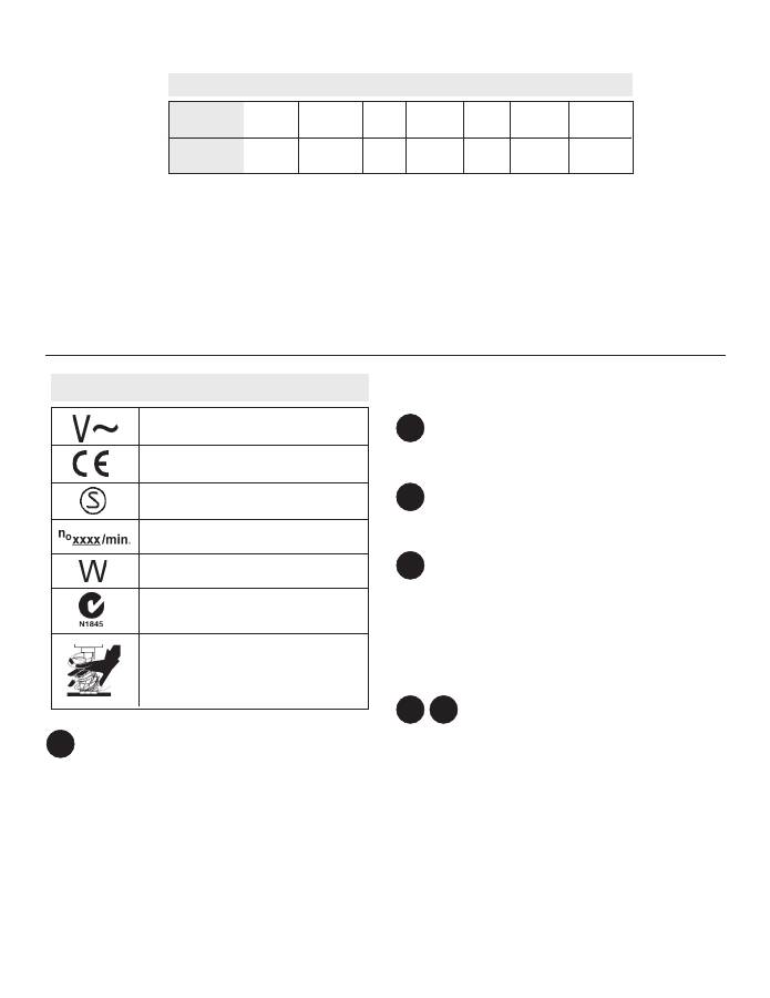
Alternating Current
Symbology
Watts
1050
Specifications
Arbor
Bore
19 mm
Article
No.
4270-50
No Load
RPM
450
Volts
AC
220-240
Catalog
No.
MDE 38
Compact
Assembly
Attaching Feed Handles and Grips
1.
Attach the feed handles and grips to the hub. Tighten securely.
2.
Mount the hub to either side by aligning the two (2) dowel pins on the
hub with the holes in the pinion. Tighten the handle screw.
Stop Knob
23 -
Stop knob
The stop knob stops the slide from moving. To install, screw the stop
knob into the location shown.
Adjusting the Gib Assembly
To adjust the gib, loosen or tighten the gib adjustment set screws on the
side of the housing accordingly with the 3/32" hex key provided.
Tightening the set screws increases friction on the slide. The gib should
be set tight enough to support the weight of the drill in any position. All
adjustment set screws should be set to provide smooth and even travel
over the entire length of slide movement.
The set screws contain a nylon patch that prevents them from moving
freely. Additional adjustment of the gib may be required over time with
extended use of the tool.
Adjusting the Support Bracket and Spacer for
Depth of Cut
24 - Spacer
25 - Support bracket
This unit is shipped from the factory set for 1" (25mm) depth cutters (Fig.
E). When using 2" (50mm) depth cutters, install the support bracket with
the spacer on bottom (Fig. F).
NOTE:
Do not use a spacer and support bracket with a chuck adapter.
C
Twist
Drill
13 mm
HSS
Cutter
38 mm
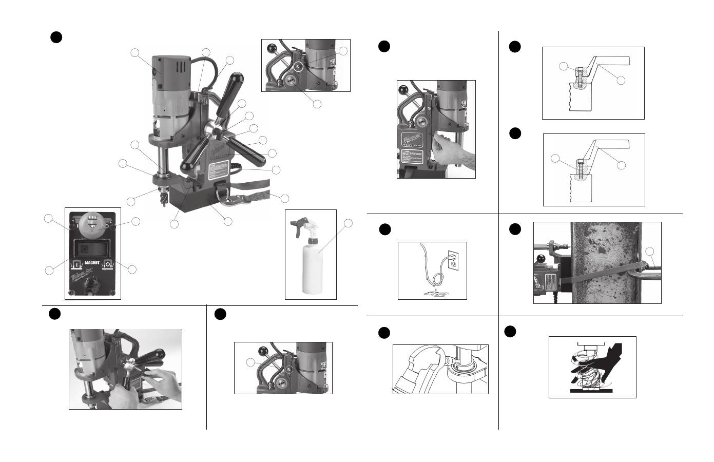
1
-
Drill motor
2
-
Slide
3
-
Wrench storage
4
-
Stop knob
5
-
Pinion
6
-
Hub
7
-
Handle screw
8
-
Feed handle
9
-
Grip
10 -
Housing
11 -
Cord
DANGER!
To reduce the risk of injury, always
keep hands, rags, clothing, etc. away from
moving parts and chips. Do not try to remove
chips while the cutter is rotating. Chips are
sharp and can pull objects into moving parts.
12 -
Safety strap
13 -
Magnetic base
14 -
Spacer
15 -
Drill spindle
16 -
Support bracket
17 -
Cutting fluid reservoir
18 -
Control panel
19 -
Magnet indicator light
20 -
Magnet switch
21 -
Drill on/off switch
22 -
Hand pump
E F
CE Conformity Mark
SEMKO Safety Mark
No Load Revolutions per Minute (RPM)
Watts
Australian C-tick Mark
3
WARNING!
To reduce the risk of injury, always use a safety strap when drilling
overhead or on a vertical surface.
26 -
C-clamp
6.
Use a safety strap on vertical or overhead situations (Fig. H).
A. Route the safety strap, ring side first, through the lower slot,
and wrap it tightly around a solid, rigid structure as shown.
Make sure the strap is not twisted.
B. Hook the safety strap snaphook provided to the ring.
Remove any slack in the strap.
C. When using on a vertical surface, secure the safety strap
with a c-clamp or similar device. This will hold the strap in
place and prevent the tool from sliding down the vertical
surface.
NOTE
: Do not clamp to the strap. This may damage the strap
and cause it to break (Fig. H).
7.
With the drill on/off switch in the "OFF" position, fill the cutting fluid
reservoir with cutting fluid through the slots in the drill spindle
(Fig. I).
The cutting fluid reservoir will empty as the center pin contacts the
work surface. When notching or slotting, it is required to spray
cutting fluid directly onto the cutter and work piece with the sup
plied hand pump. Keep hand pump away from moving parts. Failure
to use the lubricant properly will cause cutter damage.
The use of HAWG WASH® cutting fluid is recommended for long life
of these cutters. The operator is responsible for the application of
lubricants other than HAWG WASH® cutting fluid.
In overhead or vertical cutting applications, do not use cutting
fluids. Use only lubricant pastes or sprays recommended for high
speed cutting. Do not allow lubricant pastes and sprays to enter tool.
8.
Start the drill motor by pulling the drill on/off switch to the "ON" position.
WARNING!
To reduce the risk of injury, always keep hands, rags, clothing, etc.
away from moving parts and chips. Do not try to remove chips
while the cutter is rotating. Chips are sharp and can pull objects
into moving parts.
WARNING!
Excessive force will break magnet free.
9.
When feeding the cutter into the material, apply only enough force to
produce a curled chip. Applying too little force will result in small broken
chips and increased cutting time. Applying too much force will cause
overheating of the cutter resulting in short cutter life. Overheating of
the cutter can be noticed when cutter and chips turn brown or blue.
Excessive force can cause the cutter to slow down to a point where
cutting time will increase. The use of cutting lubricants will reduce
cutting heat and increase cutter life
Use less feed pressure when slotting or notching because there is less
support for the cutting edges in these situations.
English
Features
Line Lockout
The line lockout prevents the drill motor from starting when line power is
first applied to the system or after a momentary power loss. To reset
tool, turn magnet switch to "OFF" position and drill on/off switch to "OFF"
position.
Motor/Magnet Interlock
The motor/magnet interlock is a feature that prevents power from being
applied to the drill motor if the magnet is not energized. The motor magnet
interlock also prevents the magnet from being de-energized while the
motor is running.
Operation
WARNING!
To reduce the risk of injury, wear safety goggles or glasses with
side shields.
Typical Operation
1.
Check the work surface to make sure it is clean and free of foreign
materials.
Paint, rust, scale or uneven surfaces decrease the holding strength
of the magnet. Chips, burrs, dirt and other foreign materials on the
surface of the magnetic base will also decrease holding power. Use
a smooth, flat file to keep the magnet clean and free of nicks.
The electromagnetic drill press attaches magnetically to 9,5 mm or
thicker ferrous stock. Do not use on stock less than 9,5 mm. The
magnetic base WILL NOT hold on nonmagnetic grades of stainless
steel.
2.
To install/remove cutter:
A.
Raise the drill motor to its highest position. Tighten stop knob.
B.
Insert cutter into drill spindle with the two (2) flats of the cutter
aligned with set screws. Make sure the center pin is inserted
into the cutter.
NOTE:
Cutter should be fully seated into drill spindle.
C. Tighten set screws with 3/16" hex key provided.
D. Loosen the stop knob.
E. Reverse procedure to remove cutter.
NOTE:
Do not remove cutter unless slug is removed. Slug may
eject unexpectedly.
Avoid contact with cutter tips. Periodically inspect the cutter tips for
loose or damaged tips.
3.
Plug in tool to power source.
WARNING!
•
Do not use cutting fluid in an overhead or any other position
that allows cutting fluid to enter motor or switch enclosure.
•
Wet connections are shock hazards. Prevent cutting fluid
from traveling along cord and contacting the outlet, extension
cord connections or tool plug. Each time tool is plugged in,
elevate extension cord or gang box connections and arrange
a drip loop (Fig. G). If plug or connections get wet, turn power
off to outlet before unplugging tool.
4.
Move the spindle up so the cutter and center pin are above the work
surface.
WARNING!
To reduce the risk of injury, do not hold workpiece by hand.
5.
Position the center pin directly over the desired cutting location. Push
the magnet switch to the “ON” position. The magnet indicator light will
turn on.
G H J I

4
English
10. Keep constant pressure throughout the entire operation to
prevent chips and burrs from falling under the cutting edges. Cutting
debris under the cutter can make cutting difficult or
impossible.
11. When the cut is complete, withdraw the cutter while the drill spindle is
still rotating.
12. Stop the drill motor by pushing in the drill on/off switch to the "OFF"
position.
13. When the drill spindle has stopped rotating, use a pliers to remove
cutting debris and chips from the cutter and spindle. Use care to avoid
damaging the cutter teeth.
14. To eject the slug from the cutter, rotate the feed handle to highest
position.
The center pin is spring loaded. Protect people and property from
ejected slug below the cutting area.
15. Firmly grip the tool and push the magnet switch to the "OFF" position.
The magnet indicator light will turn off.
Maintenance
WARNING!
To reduce the risk of personal injury and damage, never immerse
your tool, battery pack or charger in liquid or allow a liquid to flow
inside them.
Cleaning
Clean dust and debris from charger and tool vents. Keep the tool handles
clean, dry and free of oil or grease. Use only mild soap and a damp cloth
to clean your tool since certain cleaning agents and solvents are harmful
to plastics and other insulated parts.
Repairs
Use only identical
MILWAUKEE replacement parts. Always take the tool
to an authorized
MILWAUKEE service center for repairs and
maintenance.
