Hach-Lange LICO 690 Basic User Manual – страница 3
Инструкция к Hach-Lange LICO 690 Basic User Manual
Angezeigter Fehler Ursache Beseitigung
USB-Speicher ist nicht verbunden. Update nicht möglich. Überprüfen Sie den USB-Speicher.
Versuchen Sie die Verbindung zu einem späteren
Web Server nicht erreichbar. Geräte Homepage nicht erreichbar
Zeitpunkt nochmal.
Deutsch 41
Ersatzteile
Zubehör
Beschreibung Kat.- Nr.
Zertifizierter Testfiltersatz zur Eigenkontrolle (Prüffiltersatz) 4 Präzisionsglasfilter mit Nennwerten LZM339
Zertifizierter Prüflösungssatz „Addista-color“, bestehend aus 6 zertifizierten Prüflösungen LZM282
11 mm-Rundküvette, Glas, 560 Stück LYY621
10 mm-Rechteckküvetten, Glas, 3 Stück LZP045
10 mm-Rechteck-Kunststoffküvetten, PS, 1000 Stück EBK019
50 mm-Rechteckküvette, Glas, 1 Stück LZP167
50 mm-Rechteckküvette, PMMA mit Deckel, 10 Stück LZP341
50 mm-Rechteckküvette, PMMA, 50 Stück LZM130
Hand-Barcodescanner LZV566
USB-Speicherstick LZV568
USB-Tastatur (US-Tastaturlayout (QWERTY)) LZV582
Hach Lange Online Data zur direkten Datenübernahme in MS EXCEL LZV799
Schutzkappe für USB-Schnittstelle LZV881
USB Verlängerungskabel LZV567
Ethernet Kabel, abgeschirmt, 2 m (6,56 ft) Länge. LZV873
Schnittstellenkabel USB - Computer LZV632
Deutsch 42
English
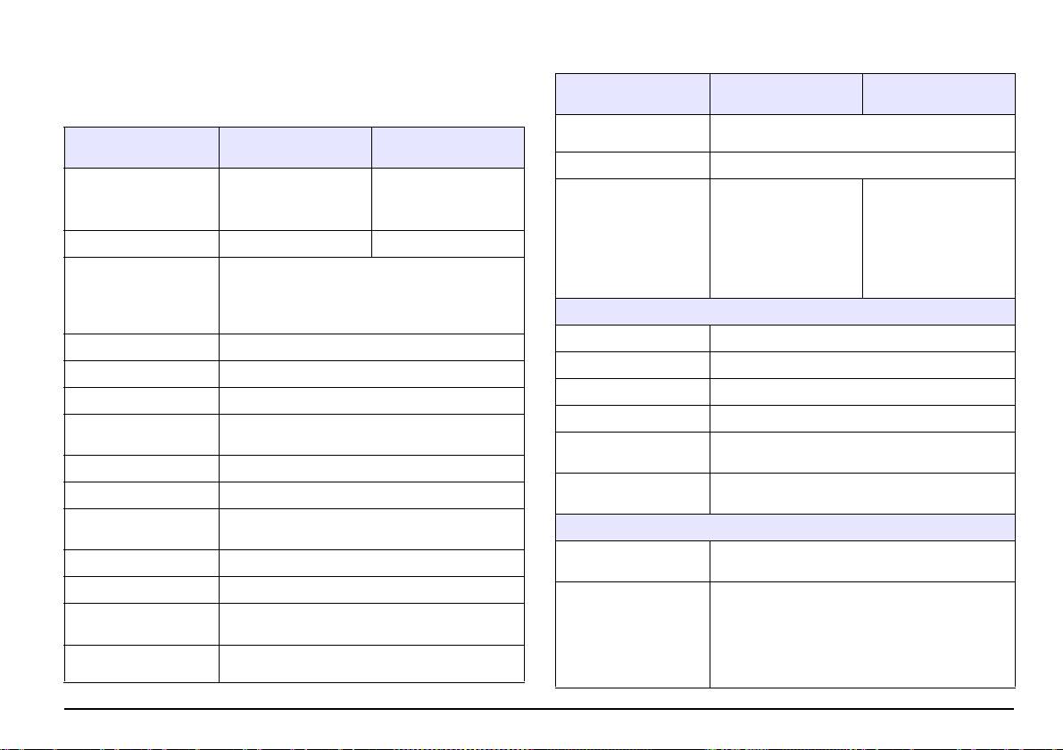
Specifications
Performance
LICO 690 LICO 620
specifications
These are subject to change without notice!
< 0,5 % to 2 Abs
Photometric linearity
Performance
≤1 % at > 2 Abs with neutral glass at 546 nm
LICO 690 LICO 620
specifications
Stray light < 0,1 % T at 340 nm with NaNO
2
Color measurement, color
difference measurement,
3000 color
Display mode
Color measurement
absorbance and
measurements,
concentration
100 color reference
values,
Data log
400 color measurements
Color measurement 26 color ratios 5 color ratios
1000 photometric
measurements,
All visual color ratios are calculated for standard light
20 wavelength scans, 20
chart C and 2° standard observers in accordance with
time scans
Colorimetric evaluation
DIN 5033. Colorimetric color values can be switched
to light type A, C, D65 and 2° or 10° standard
Physical and environmental specifications
observers.
Width 350 mm (13,78 in)
Source lamp Halogen lamp
Height 151 mm (5,94 in)
Wavelength range 320–1100 nm
Depth 255 mm (10,04 in)
Wavelength Accuracy ± 1,5 nm (wavelength range 340–900 nm)
Earth 4200 g (9,26 lb)
Wavelength
≤ 0,1 nm
reproducibility
Ambient operating
10–40 °C (50–104 °F), maximum 80 % relative
requirements
humidity (without condensate formation)
Wavelength resolution 1 nm
Ambient storage
–40–60 °C (–40–140 °F), maximum 80 % relative
Wavelength calibration Automatic
requirements
humidity (without condensate formation)
Wavelength range for
380–720 nm steps of 10 nm
Additional technical data
color measurement
Power connector via
Input: 100–240 V/47–63 Hz
Scanning speed ≥ 8 nm/sec (in steps of 1 nm)
external power supply
Output: 15 V/40 VA
Spectral bandwidth 5 nm
Use only shielded cable with maximum length of 3 m:
2× USB type A
Photometric measuring
± 3 Abs (wavelength range 340–900 nm)
range
1× USB type B
Interfaces
Use only shielded cable (for example STP, FTP, S/
5 mAbs at 0,0–0,5 Abs,
Photometric accuracy
FTP) with maximum length of 20 m:
1 % at 0,50–2,0 Ext
1× Ethernet
English 43
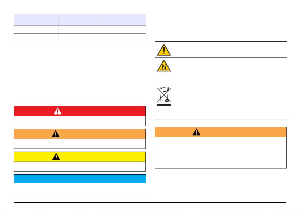
Performance
Precautionary labels
LICO 690 LICO 620
specifications
Read all labels and tags attached to the instrument. Personal injury or
damage to the instrument could occur if not observed. For symbols
Housing rating IP40 (excluding interfaces and power supply)
attached to the device, corresponding warning notes are found in the
Protection class Class I
user manual.
This symbol may be attached to the device and references the
General Information
operation- and/or safety notes in the user manual.
Safety information
This symbol on the device is an indication of hot surfaces.
Read through the entire user manual carefully before you unpack the
device, set up and put into operation. Pay attention to all danger and
caution statements. Failure to do so could result in serious injury to the
Electrical equipment marked with this symbol may not be disposed of
operator or damage to the equipment.
in European domestic or public disposal systems after 12 August
2005. In conformity with European local and national regulations (EU
To make sure that the protection provided by this instrument is not
Directive 2002/96/EC), European electrical equipment users must
impaired, do not use or install this instrument in any manner other than
now return old or end-of life equipment to the manufacturer for
that specified in these operating instructions.
disposal at no charge to the user.
Note: For return for recycling, please contact the equipment
manufacturer or supplier for instructions on how to return
end-of-life equipment, manufacturer-supplied electrical
DANGER
accessories, and all auxiliary items for proper disposal.
Indicates a potentially or imminently hazardous situation that, if not avoided,
results in death or serious injury.
WARNING
WARNING
The manufacturer is not responsible for any damages due to misapplication or
Indicates a potentially or imminently hazardous situation that, if not avoided, may
misuse of this product including, without limitation, direct, incidental and
result in death or serious injury.
consequential damages, and totally excludes such damages as permitted under
applicable laws.
The user is solely responsible to identify critical application risks and install
CAUTION
appropriate mechanisms to protect processes during a possible equipment
Indicates a potentially hazardous situation that may result in minor or moderate
malfunction.
injury.
NOTICE
Indicates a situation that, if it is not avoided, can lead to damage to the device.
Information that requires special emphasis.
Note: Information that supplements points in the main text.
English 44
Safety around source lamps
Overview of product
The source lamp is operated at high temperatures.
The LICO 690 and LICO 620 instruments are VIS spectral-photometers
with wavelength ranges from 320 to 1100 nm. The instruments can
To prevent electric shock, disconnect the instrument from the power
perform a precise colorimetric analysis in accordance with ISO/ASTM
source before replacing the lamp.
standards with a single measurement and display the result in the form
of classic color systems such as iodine, Hazen or Gardner color values.
The instruments support multiple languages.
CAUTION
The LICO 690 is supplied with 26 color value calculations, while the
Burn hazard. Allow the lamp(s) to cool for at least 30 minutes before maintaining/
LICO 620 is supplied with five color value calculations (Iodine color,
replacing them.
Hazen color, Gardner color, Saybolt color and ASTM D 1500 color
numbers).
Chemical and biological safety
The LICO 690 contains the following programs and operating modes in
addition to the color measurement: single wavelength mode, multi-
wavelength mode, wavelength scan and time scan mode. The digital
DANGER
measurements are displayed in the dimensional units of concentration,
Potential danger with contact with chemical/biological substances.
absorbance or % transmittance, making the LICO 690 universally
Working with chemical samples, standards and reagents can be dangerous.
suitable for lab analysis.
Make yourself familiar with the necessary safety procedures and the correct
handling of the chemicals before use and read and follow all relevant safety data
sheets.
Installation
Normal operation of this device may require the use of chemicals or
samples that are biologically unsafe.
• Observe all cautionary information printed on the original solution
WARNING
containers and safety data sheets prior to their use.
Electrical and fire hazards.
Only use the supplied benchtop power supply LZV844.
• Dispose of all consumed solutions in accordance with the local and
Only qualified experts may perform the tasks described in this section of the
national regulations and laws.
manual, while adhering to all locally valid safety regulations.
• Select the type of protective equipment suitable to the concentration
and quantity of the dangerous material being used.
English 45
Unpacking the instrument
Operating environment
The following components are supplied as standard with the LICO 690/
Observe the following points to allow the instrument to function normally
620:
and give a long operating life.
• LICO 690/LICO 620 spectrophotometer
• Position the instrument securely on a flat surface taking care to
remove any objects from under the device.
• Dust cover
• The ambient temperature must be 10–40 °C (50–104 °F).
• USB dust cover, fitted as standard
• Table power supply with power cord
• Cuvette adapter Z, installed as standard
NOTICE
Protect the instrument from extreme temperatures from heaters, direct sunlight
• Basic user manual
and other heat sources.
• CD-ROM with detailed operating instructions
• The relative humidity should be less than 80 %; moisture should not
Note: If any of these items are missing or damaged, please contact the
condense on the instrument.
manufacturer or a sales representative immediately.
• Leave at least a 15 cm clearance at the top and on all sides for air
circulation to avoid overheating of electrical parts.
• Do not use or store the device in extremely dusty, humid or wet
places.
• Keep the surface of the instrument, the cell compartment and all
accessories clean and dry at all times. Immediately remove
splashes or spilt materials on or in the instrument.
English 46
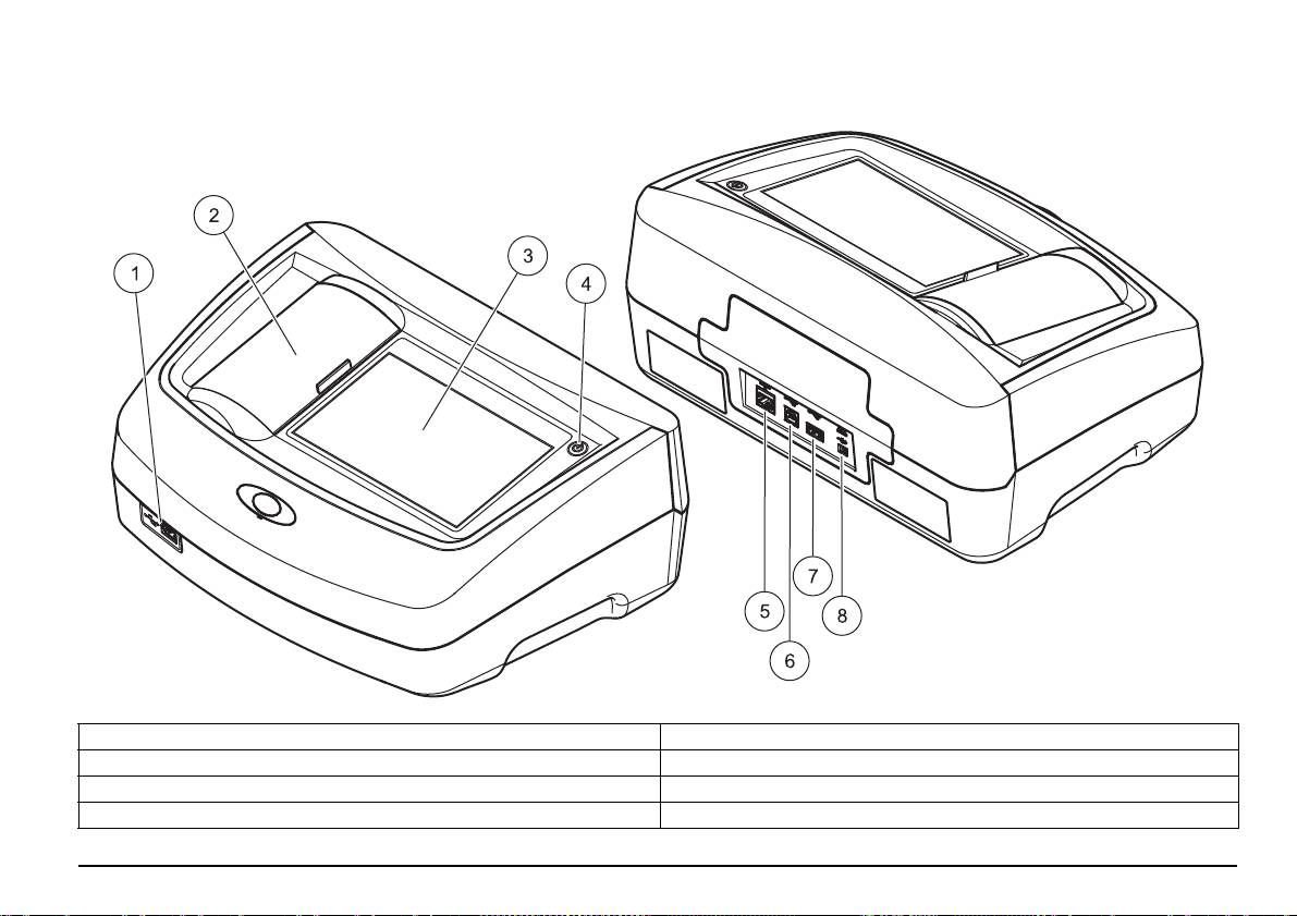
Front and back view
Figure 1 Front and back view
1 USB port type A 5 Ethernet port
2 Cuvette compartment cover 6 USB port type B
3 Touch screen 7 USB port type A
4 On/off switch 8 Connection for benchtop power supply
English 47
Power connections
Table 1 Interfaces
Interfaces Description
WARNING
This USB port can be used to connect a printer, a USB memory
USB (Type A)
stick or a keyboard.
Electrical and fire hazards.
Only use the supplied benchtop power supply LZV844.
This USB port is intended only for the connection between the
USB (Type B)
instrument and a PC (when the relevant software is installed).
1. Connect the power cable to the benchtop power supply.
The Ethernet port is intended for data transfer to a PC without
2. Plug the benchtop power supply cable into the back of the
installed software or in a local network . Only use a shielded
Ethernet
instrument (Figure 1).
cable (e.g. STP, FTP, S/FTP) with a maximum length of 20 m for
the Ethernet port.
3. Insert the power cable plug into a mains socket (100–240 V~/47–
63 Hz).
4. Turn on the power switch next to the screen to activate the power
Cuvette compartments and cuvette adapters
supply (Figure 1).
Cuvette compartments and adapter
Note: If you do not intend to use the instrument for a long period,
disconnect it from the power supply.
Open the cuvette compartments by sliding the cuvette compartment
cover to the left.
Note: Make sure the socket you are using is easily accessible.
The cover lowers to the side next to the cuvette compartments.
Interfaces
Note: If there are long intervals between uses, close the cuvette
compartment cover to protect the optics of the instrument from dust and
The instrument has three USB ports and one Ethernet port as standard.
impurities.
They are located on the front and rear of the instrument (Figure 1).
The instrument has two cuvette compartments (Figure 2). Only one cell
The USB type A ports are used for communications with a printer, USB
type at a time can be used for a reading.
memory stick or keyboard. A USB memory stick can be used to update
the instrument software.
Cell compartment (1) for:
The USB type B port is used for communications with a PC. The
• 11 mm round cuvettes
optional Hach Lange Online Data software must be installed on the PC
Note: Insert cuvette adapter Z into the cuvette compartment (2).
for this use.
A USB hub may be used to connect several accessories at a time.
Cell compartment (2) for:
Note: USB cables must not be longer than 3m.
The following cell types can be used in cell compartment (2).
These USB ports permit data to be exported to a printer or PC and also
• Without cuvette adapter Z in the cuvette compartment (2), you can
allow the instrument software to be upgraded. The Ethernet port
insert 50 mm cuvettes.
supports real-time data transfer in local networks, LIMS systems or SC
• With cuvette adapter Z: 10 mm square cuvettes.
controllers. Only use a shielded cable (e.g. STP, FTP, S/FTP) with a
Note: These cuvettes must be inserted with cuvette adapter Z.
maximum length of 20 m for the Ethernet port.
English 48
Note: In the event of severe contamination, you can replace the cuvette
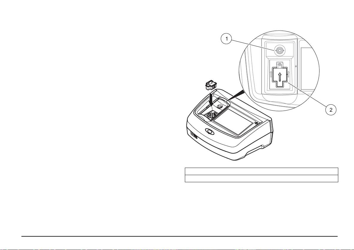
Figure 2 Cuvette compartments and cuvette adapter Z
compartment (2).
Installation of cuvette adapter Z
1. Open the cuvette compartment.
2. Insert cuvette adapter Z into the cuvette compartment (2) so that
the arrow on the cuvette adapter is pointing toward the cuvette
compartment (1) (Figure 2).
Note: The arrow on the cuvette adapter indicates the direction of the light
beam path.
1 Cuvette compartment (1) for round cuvettes
2 Cuvette compartment (2) for square cuvettes, cuvette adapter Z installed
English 49
Start Up
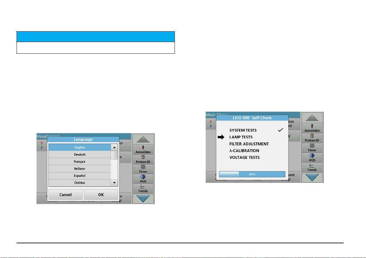
2. Press OK to confirm the language selection. The self-check will
then start automatically.
Change the language setting
NOTICE
The instrument functions in the selected language until the option is
All screen displays in this operating manual correspond to the LICO 690. The
changed.
screen displays of the LICO 620 may differ.
1. Turn the instrument on.
2. During the startup process, touch any point on the screen and
Switch on the instrument, startup process
maintain contact until the option for selecting a language is shown
1. Connect the power cable to the mains outlet.
(approximately 45 seconds).
2. Switch on the instrument by pressing the power switch next to the
3. Select the required language.
screen.
4. Press OK to confirm the language selection. The self-check will
3. The instrument starts automatically with a startup process lasting
then start automatically.
approximately 45 seconds. The screen displays the manufacturer's
logo. At the end of the startup process, a startup melody is heard.
Self-check
Note: Wait approximately 20 seconds before switching on again so as
not to damage the electronics and mechanics of the instrument.
Language selection
Each time the instrument is powered up, a test program begins.
During the course of this program (approx. 25 seconds), system tests,
lamp tests, filter calibration, wavelength calibration and voltage tests can
The software supports multiple languages. The first time the instrument
be carried out. Each test that functions correctly is marked accordingly.
is switched on, the language selection screen will be shown
Note: For error messages during the test program, refer to
automatically after the startup process.
Troubleshooting.
1. Select the required language.
English 50
Power off the instrument
1. Press the power switch next to the screen for approx. 5 seconds.
Standard programs
Overview
Tips for using the touch screen
The whole screen responds to touch. To choose an option, tap with a
fingernail, fingertip, an eraser or a specialised stylus. Do not touch the
screen with sharp objects, such as the tip of a ballpoint pen.
• Do not place anything on top of the screen, to prevent damage or
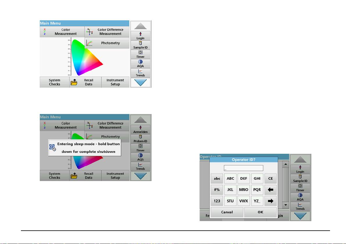
The Main Menu is displayed when diagnostics are completed.
scratching on the screen.
• Press buttons, words or icons to select them.
Sleep mode
• Use scroll bars to move up and down long lists very quickly. Press
and hold the scroll bar, then move up or down to move through the
list.
• Highlight an item from a list by pressing it once. When the item has
been successfully selected, it will be displayed as reversed text
(light text on a dark background).
Use of the alphanumeric keypad
The instrument can be put into sleep mode.
1. Briefly press the power switch next to the screen.
The "Sleep mode" message is shown. The screen will then switch
off automatically.
2. To switch on, press the power switch next to the screen.
The self-check will start automatically.
After that, the instrument is ready to use.
English 51
This display is used to enter letters, numbers and symbols as needed
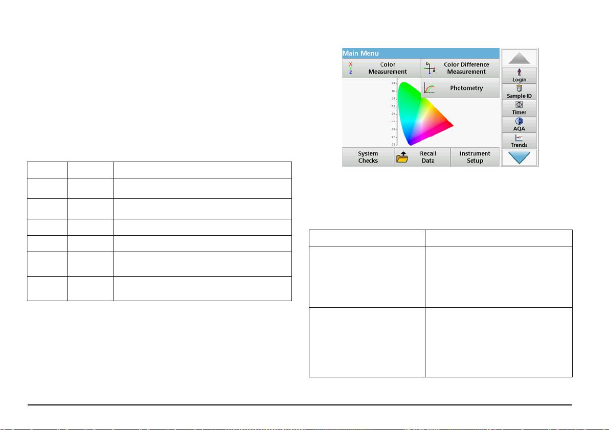
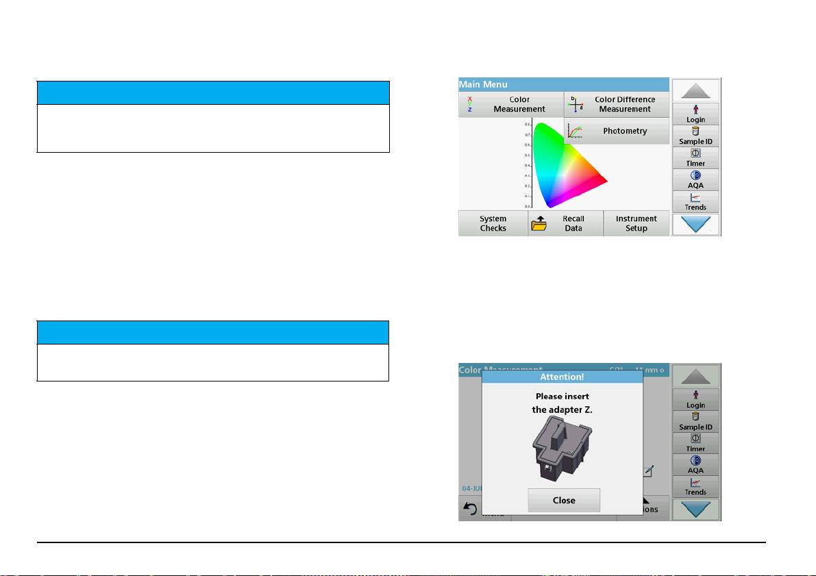
Main menu
when programming the instrument. Unavailable options are disabled
(grayed out). The icons on the right and left of the screen are described
in Table 2.
The central keypad changes to reflect the chosen entry mode. Press a
key repeatedly until the desired character appears on the screen. A
space can be entered by using the underscore on the YZ_ key.
Press Cancel to cancel an entry, or press OK to confirm an entry.
Note: It is also possible to use a USB keyboard (with US keyboard
layout) or a hand-held USB barcode scanner.
Table 2 Alphanumeric keypad
Icon / key Description Function
A variety of modes may be selected from the Main Menu. The following
Toggles the character input mode between upper and
table briefly describes each menu option.
ABC/abc Alphabetic
lower case.
There is a toolbar on the right-hand side of the screen. Press to activate
Punctuation, symbols and numerical sub- and
# % Symbols
the various functions.
superscripts may be entered..
Table 3 Main Menu options
123 Numeric For entering regular numbers..
Option Function
CE Clear Entry Clear the entry.
The COLOR MEASUREMENT MODE is
Left
Deletes the current character and goes back one
used to determine color values such as
Back
Arrow
position.
Hazen, Gardner and Saybolt. The LICO 690
Color measurement
also offers three-dimensional, absolute
Right
colorimetric values, as well as the color
Next Navigates to the next space in an entry.
Arrow
scales of CIE L*a*b*, Hunter Lab or the
European Pharmacopoeia.
The mode for COLOR DIFFERENCE
MEASUREMENT is used to determine a
quantitative color difference between a
Color difference measurement
reference (R) and a sample (P) in the three-
(only LICO 690)
dimensional color space (CIE L*a*b* or
Hunter Lab). In this mode, an additional
reference memory for up to 100 references
is available.
English 52
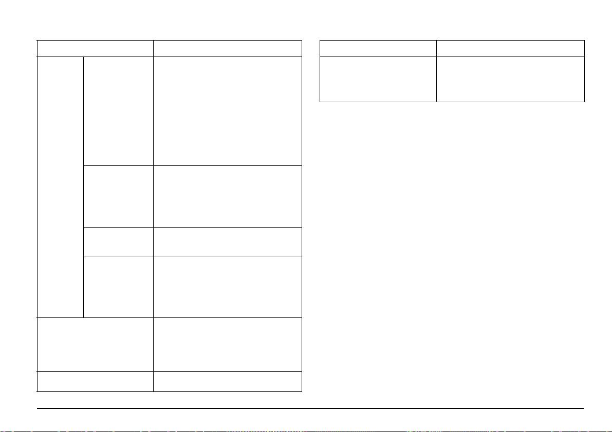
Table 3 Main Menu options
Table 3 Main Menu options
Option Function
Option Function
Single wavelength readings are:
This menu is used to configure user-specific
Absorbance readings: The light absorbed
and/or process-specific settings: operator ID,
by the sample is measured in absorbance
Instrument Setup
date and time, security settings, saved data,
units.
sound, PC and printer and energy
management.
Transmittance reading (%): Measures the
percent of the original light that passes
Single Wavelength
through the sample and reaches the
Take and prepare samples
detector.
Take a representative sample from the product you wish to measure in
Concentration readings: A concentration
accordance with DIN EN ISO 15528 (or ASTM D3925-02).
factor can be entered to enable the
measured absorbance values to be
If the material shows any signs of turbidity, remove this turbidity by
converted into concentration values.
filtration, centrifuging, heating, ultrasound treatment or other suitable
In the Multi Wavelength mode, absorbance
means.
Photometry
(Abs) or percentage transmittance (%T) is
Heat partly solid samples before measuring in order to dissolve the solid
(only
measured at up to four wavelengths and
LICO 690)
Multi Wavelength
absorbance differences and absorbance
material in the liquid. The preparation must not cause any chemical
relationships are calculated. Simple
changes in the sample.
conversions into concentrations can also be
Make sure that during the measurement there are no bubbles in the
carried out.
sample.
The time scan records the absorbance or %
Time course
transmittance at a wavelength over a defined
For the color difference measurement, three cuvette types are available
time.
that differ in terms of material (glass, PS and PMMA) and path length
(10 mm, 11 mm and 50 mm). Add approx. 2 cm of the sample to the
A wavelength scan shows how the light from
cuvette. The light beam passes through the cuvette approx. 0,5 cm to
a sample is absorbed over a defined
wavelength spectrum. This function can be
1,5 cm above the bottom of the cuvette.
Wavelength Scan
used to determine the wavelength at which
The program calculates the iodine, Hazen, Gardner, Saybolt, Klett and
the maximum absorbance value can be
ASTM D 1500 color values automatically and displays the color values.
measured. The absorbance behavior is
The cuvette type being used is taken into consideration.
displayed graphically during the scan.
The "System Check" menu contains a
number of options, such as instrument
information, optical checks, instrument
System Checks
backup, service times, instrument update,
settings for analytical quality assurance and
lamp history.
Saved data can be retrieved, filtered, sent to
Recall measurement data
a printer, memory stick or PC and deleted.
English 53
A dry thermostat is available for the round disposable glass cuvettes
• Slowly add the liquid to the cuvette in order to prevent the formation
with 11 mm. The dry thermostat heats up the cuvette to any temperature
of air bubbles in the sample.
between ambient temperature and 150 °C (302 °F).
NOTICE
The samples must be clear and free of turbidity. If products in paste or solid form
cannot be measured directly, the product must be melted before being transferred
to the cuvettes/sample cells. Make sure the cuvettes/sample cells do not contain
any air bubbles.
• Always hold the cuvette/sample cell close to the top to make sure
that there are no fingerprints in the measurement zone of the
cuvette/sample cell. Use suitable transfer pipettes to introduce
samples into the cuvettes/sample cells.
• Slowly add samples to the cuvettes/sample cells to make sure air
bubbles do not form on the cuvette/sample cell wall and in the
sample. Air bubbles will cause false readings.
The color measurement mode is used to determine absolute color
values in the Hazen, Gardner, CIE L*a*b* or European Pharmacopoeia
• If air bubbles are entrapped, remove them by heat, vacuum,
color scales.
ultrasonic treatment or other suitable means.
For each cuvette type (11 mm round cuvette and 10 and 50 mm square
• Clean the outside of the cuvettes/sample cells thoroughly before
cuvettes), an independent calibration data record is used.
inserting them in the cell compartment.
It is possible to calibrate the instrument with one, two or three types of
cuvettes/sample cells and to use these different cuvette/sample cell
NOTICE
types in parallel.
Before using disposable cuvettes/sample cells made of PS (Polystyrene) or
PMMA (Polymethyl methacrylate), be sure that the cuvettes/sample cells will not
be destroyed by samples, otherwise the cell compartment can be damaged.
Color measurement
Proper sample preparation is extremely important for accurate color
measurement. To make sure that an exact measurement is taken, refer
to the following sample preparation guidelines:
• Always clean the glass cuvettes/sample cells immediately after use.
• Only use optically preferred samples for measurement. Make sure
the cuvettes/sample cells are clean and show no signs of
opaqueness.
English 54
To use the 10 mm square cuvette and 11 mm round cuvettes, adapter Z
3. The calibration starts automatically once the instrument has
must be inserted into the cuvette compartment (2). For measurements
detected the cuvette.
with 50 mm square cuvettes, you must remove the adapter.
The type of cuvette/sample cell used and the exact progress of
calibration is shown in a separate window.
Take a color measurement
4. After calibration, the cuvette size used is displayed in the top right.
1. Press Color Measurement.
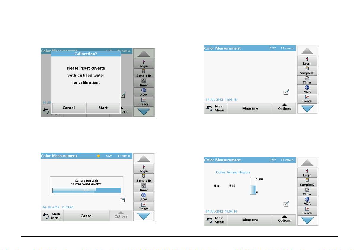
Note: After calibration, you can measure the cuvette with distilled
2. Insert a cuvette/sample cell with distilled water to calibrate.
water again as a sample.
Note: Always carry out the calibration very carefully, as a faulty
The displayed measured values should match the uncolored color
calibration can cause inaccurate results to be obtained.
indices (i.e. Hazen = 0, Gardner = 0.0, CIE L*a*b* = 100.0, 0.0, 0.0,
etc.)
English 55
5. Insert the test cuvette.
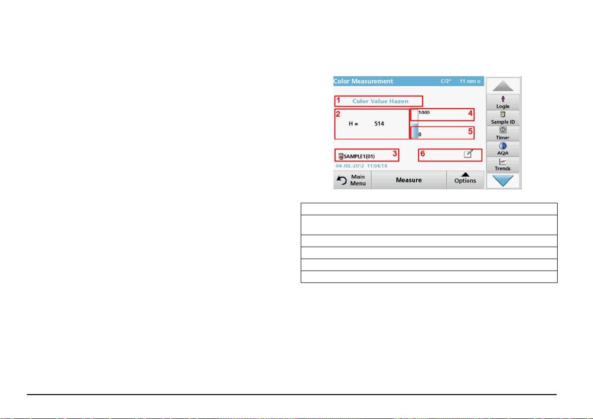
Touch-sensitive areas in measurement mode
The measurement starts automatically.
In measurement mode, there are touch-sensitive areas that give you
The result of the color calculation is displayed.
immediate access to various menu options.
Note: The bar on the right next to the result shows the result relative
Figure 3 Touch-sensitive areas in measurement mode
to the measurement range.
6. For the next measurement, remove the cuvette and insert the next
sample cuvette, or press Measure to measure the same sample
again.
1 Open Select Color Scale, and select the scale for the display.
2 Change the displayed color scale to the next color system which is selected
in the Operator ID color scale list for display.
3 OpenSample ID to change or add the sample ID.
4 Change the Upper Limit of the color range.
5 Change the Lower Limit of the color range.
6 Open Comments to enter a comment.
Parameter setup options
Press Options to set up the parameter.
English 56
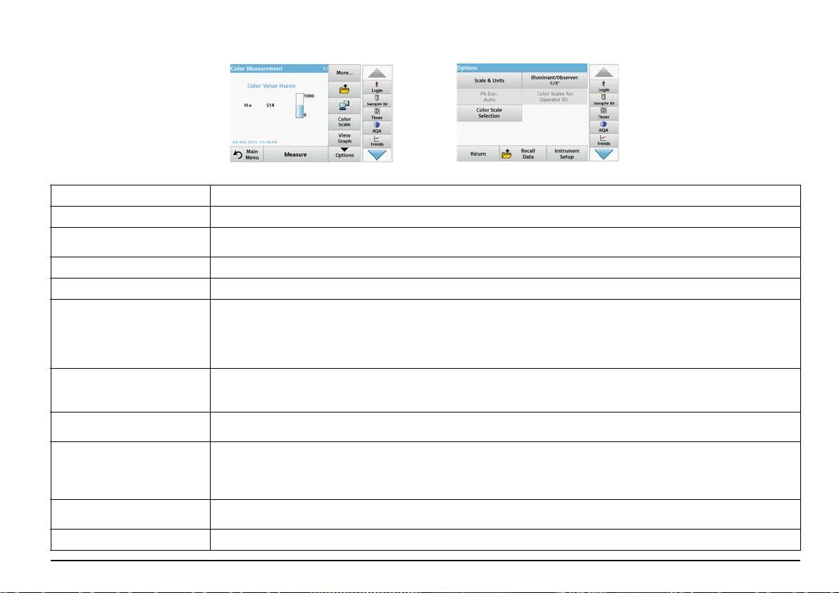
Table 4 Color measurement options
Options Description
More For further Options
Symbol: Store Data, if Instrument Setup > Data Log Setup > Auto Store: Off is selected.
Save icon
Symbol: Recall Data, if Instrument Setup > Data Log Setup > Auto Store: On is selected.
Send Data icon To send data to a printer, computer or USB memory stick (USB A) or network.
Color Scale Select the color scale
VIEW GRAPH shows the spectral graph of the transmittance or absorbance graph.
View Graph
Note: View Graph is activated after the first measured value.
View Table
View Values
VIEW TABLE displays the spectral transmittance values T% from 380 nm to 720 nm.
VIEW VALUESdisplays the result of the last color calculation.
UNITS: Select absorbance or transmittance.
Scale & Units
SCALE: In the automatic Scale mode, the y-axis is automatically adjusted so that the total scan is displayed.
The manual Scale mode allows sections of the scan to be displayed.
European Pharmacopoeia
Ph.Eur.: Auto
Select AUTO or the REQUIRED SCALE
Define 3 different color scale combinations with up to 3 different color scales for the result display.
Selection 1: Klett Color No. + Yellowness Index
Color Scale Selection
Selection 2: Klett Color No. + ADMI Color No. + Yellowness Index
Selection 3: Yellowness Index + individual transmittance
Illuminant: Select C, A or D65
Illuminant/Observer: C/2°
Observer: 2° or 10°
Color Scales for Operator ID Individual selection of the color scales for the operator ID.
English 57
Troubleshooting
Error displayed Definition Resolution
An error occurred when uploading the instrument
Restart the process or contact the manufacturer or
data.
national agent.
An error occurred when reading from the USB
Restart the process or contact the manufacturer or
memory stick.
national agent.
An error occurred when writing to the USB memory
Restart the process or contact the manufacturer or
stick.
national agent.
Please check on the current update file. Error during update. Check the USB memory stick.
Please contact Customer Service. Error during update. Contact the manufacturer or national agent.
Please check network configuration. Check the network setup. .
Please check the connection. Check the network setup. .
Please close the cover. Close the cuvette compartment cover.
Insert a USB memory stick into a USB A port on the
Please insert the USB memory stick.
instrument.
Please check the connection and contact the
Check the network setup or contact the manufacturer
Network setup or FTP error
administrator.
or national agent.
File for instrument update missing. Error during update. Check the USB memory stick.
File for instrument update is faulty. Error during update. Save the update file again and repeat the procedure.
Switch the instrument off and then back on again. If the
It’s recommended to execute a Full System Check Check of the air values failed
system test is unsuccessful, contact the manufacturer
or national agent.
Forgotten your password?
Entry invalid! Password incorrect
Contact the manufacturer or national agent
Absorbance > 3.5! The measured absorbance exceeds 3.5 Dilute sample and measure again
Color = *** Color value outside measurement range. Dilute the sample or select appropriate color scale.
English 58
Error displayed Definition Resolution
Network setup: DHCP client has no connection to the
Error when calling up the local IP address.
Enter the IP address again.
DHCP server
Network setup: default gateway cannot be set for fixed
Error during default gateway setup.
Try to create the connection again.
IP address
Error during network drive setup! Error during network setup Check the settings.
Network setup: Subnet mask cannot be set for fixed IP
Error during subnet mask setup.
Enter the subnet mask again.
address
Restart the process or contact the manufacturer or
Error copying from USB memory stick. Error during update
national agent.
Make sure that the instrument is connected to the
Error in FTP connection. FTP error
network.
Fault
Test program stopped!
Check the lamp and replace it if necessary.
Please check lamp
Test program stops when the instrument is started
Close lid.
Close the lid.
Press Start Again.
Error [xx]
Fault
Remove the cuvette/sample cell from the cell
Test program stopped!
Test program stops when the instrument is started
compartment.
Please remove the cuvette
Press OK.
Close the lid.
Error
Selfcheck stopped.
Contact the manufacturer or national agent and specify
Electronic defect
Hardware error.
the error number.
Error [x]
Error
Too much ambient light!
Decrease ambient light. Avoid direct sunlight.
The instrument sensors detects too much ambient light.
Move instrument into shade
Close lid.
or close the lid
No instrument backup present! Check the USB memory stick.
No valid data for these parameters! Data analysis not possible, no measurement data Change the selection.
English 59
Error displayed Definition Resolution
No valid data found! Data cannot be viewed in the data log Change the selection.
Data analysis settings cannot be configured without
No measurement data present!
Change the selection.
measurement data.
This is a warning notice. The control limit set was not
Control range not reached! Data analysis limits not reached
reached.
This is a warning notice. The control limit was
Control range exceeded! Data analysis limits exceeded.
exceeded.
Concentration too high! Calculated concentration is higher than 999999 Dilute sample and measure again
The analysis is possibly erroneous due to
Possible interference by: Interference Check
interferences.
The analysis is possibly erroneous due to
Possible interference from: Interference Check
interferences.
Contact the manufacturer or national agent for an
Next service is due!
instrument service.
Negative result! The calculated result is negative Check concentration of sample
Network setup off, when access to homepage via
Network switched off.
Activate the online connection.
sidebar
Make sure that the instrument is connected to the
Remote server cannot be reached. Error during network setup
network.
Unstable lighting conditions! Avoid direct sunlight at the measuring location.
For measurements with 11 mm round cuvettes, adapter
Insert adapter Z into cell compartment (2). Confirm with
Please insert adapter Z.
Z is required.
OK.
Insufficient memory for update . Error during update. Select a memory with more space.
Switch the instrument off and then back on again. If the
System check incorrect! Measurement of air values failed
system test is unsuccessful, contact the manufacturer
or the national agent.
Temperature too high.
Switch of the instrument and allow it to cool for a few
Measurement not possible!
minutes. If necessary, move it to a cooler place.
English 60
