Stiebel Eltron SHW ... S с 06.05.2013: InStallatIOn
InStallatIOn: Stiebel Eltron SHW ... S с 06.05.2013
20
| SHW S www.stiebel-eltron.com
InStallatIOn
Safety
InStallatIOn
7. safety
Only a qualified contractor should carry out installation, commis-
sioning, maintenance and repair of the appliance.
7.1 general safety instructions
We guarantee trouble-free function and operational reliability
only if the original accessories and spare parts intended for the
appliance are used.
7.2 instructions, standards and regulations
Note
Observe all applicable national and regional regulations
and instructions.
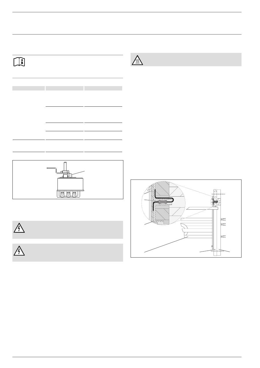
8. appliance description
8.1 standard delivery
Delivered with the appliance:
- Thermometer (delivered inside the control panel)
- Cold water inlet pipe with flat gasket
- Adhesive rose for DHW circulation line
- Adaptor with flat gasket for the connection of a DHW circula-
tion line
- Plastic cap
8.2 accessories
required accessories
Depending on the static pressure, safety assemblies and pressure
reducing valves are available. These type-tested safety assemblies
protect the appliance against unacceptable excess pressure.
Further accessories
If it is not possible to fit an anode rod from above, install a seg-
mented signal anode.
9. Preparations
9.1 installation site
Always install the appliance in a room free from the risk of frost
and near the draw-off point, and secure the appliance to the floor.
9.2 transport
!
Material damage
We recommend removing the cylinder casing during
transport to the installation location, to prevent it from
becoming dirty or damaged (see chapter "Installation /
Fitting the cylinder casing and DHW circulation line if
required").
10. installation
10.1 Fitting the cylinder casing and dHw circulation
line if required
Note
Fit the cylinder casing with cover before making the water
connection and, if necessary, the DHW circulation line or
the flanged immersion heater.
The plinth trim should be fitted after the tightness check.
A DHW circulation line can be fitted to the "DHW circulation"
connection (see chapter "Specification / Dimensions and connec-
tions"). Alternatively, the "DHW circulation" connection can be
used to connect a thermometer.
dismantling
f
f
Remove the cover and the plinth trim of the cylinder casing
one after the other.
f
f
Pull off the temperature selector on the flanged immersion
heater.
f
f
Remove the control panel cover and cable grommet.
f
f
Remove the cylinder casing.
www.stiebel-eltron.com
SHW S |
21
EN
GL
ISH
InStallatIOn
Installation
installation
f
f
Fit the cylinder casing.
f
f
Fit the cable grommet and control panel cover.
f
f
Push on the temperature selector.
f
f
If you use the "DHW circulation" connection to install a DHW
circulation line, you need to cut an opening in the cylinder
casing near the connection (indentation in the foam) for the
DHW circulation line.
f
f
Remove the thermal insulation near the connection.
f
f
Route the DHW circulation line through the aperture in the
cylinder casing and fit the DHW circulation line.
f
f
Insulate the "DHW circulation" connection.
f
f
Insert the supplied adaptor with flat gasket and an extension.
f
f
Cover the hole in the cylinder casing with the adhesive rose
supplied.
f
f
Fit the cover and the plinth trim of the cylinder casing.
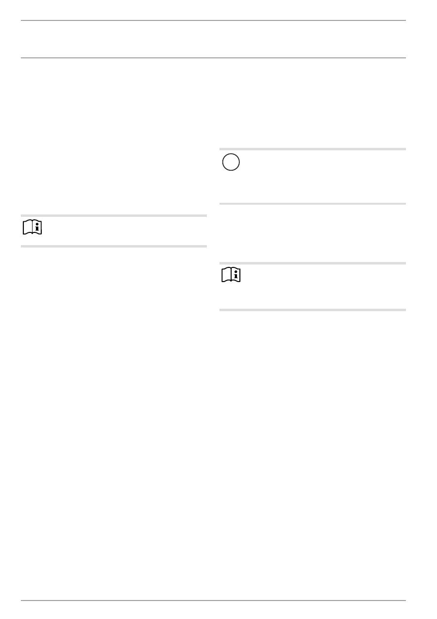
10.2 thermometer
26
�0
2�
09
�0
06
2
f
f
Insert the thermometer as far as it will go and align it.
10.3 signal anode
!
Material damage
The appliance must not be operated without a consump-
tion indicator or with a damaged one, otherwise water
will leak out once the anode is depleted.
26
�0
2�
09
�0
06
3
1
2
1 Transport protection
2 Signal anode with consumption indicator
f
f
Remove the transport protection.
f
f
Check the consumption indicator for transport damage.
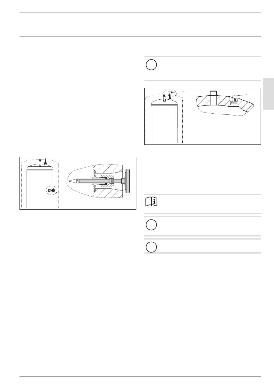
10.4 water connection and safety assembly
10.4.1 safety instructions
Note
Carry out all water connection and installation work in
accordance with regulations.
!
Material damage
When using plastic pipework, observe chapter "Specifi-
cation / Fault conditions".
!
Material damage
Operate the appliance only with pressure-tested taps.
cold water line
Galvanised steel, stainless steel, copper and plastic are approved
materials.
A safety valve is required.
dHw line
Stainless steel, copper and plastic pipework are approved ma-
terials.
22
| SHW S www.stiebel-eltron.com
InStallatIOn
Installation
10.4.2 connection
f
f
Flush the pipes thoroughly.
The max. permissible pressure must not be exceeded (see chapter
“Specification / Data table”).
ff
Install a type-tested safety valve in the cold water supply
line. Please note that, depending on the static pressure, you
may also need a pressure reducing valve.
f
f
Fit the DHW outlet pipe and the cold water inlet pipe.
26
�0
2�
09
�0
03
5
1
2
1 Cold water connection
2 Cold water supply pipe
f
f
Connect the cold water supply directly to the cylinder or with
the connecting pipe routed between the cylinder feet.
f
f
During fitting, counterhold the fitting with an open-ended
spanner (size 36).
f
f
Check the rigidity of the connecting pipe and secure it further
if required.
ff
Size the drain so that water can drain off unimpeded when
the safety valve is fully opened.
ff
Fit the discharge pipe of the safety valve with a constant
downward slope and in a room free from the risk of frost.
ff
The safety valve discharge aperture must remain open to the
atmosphere.
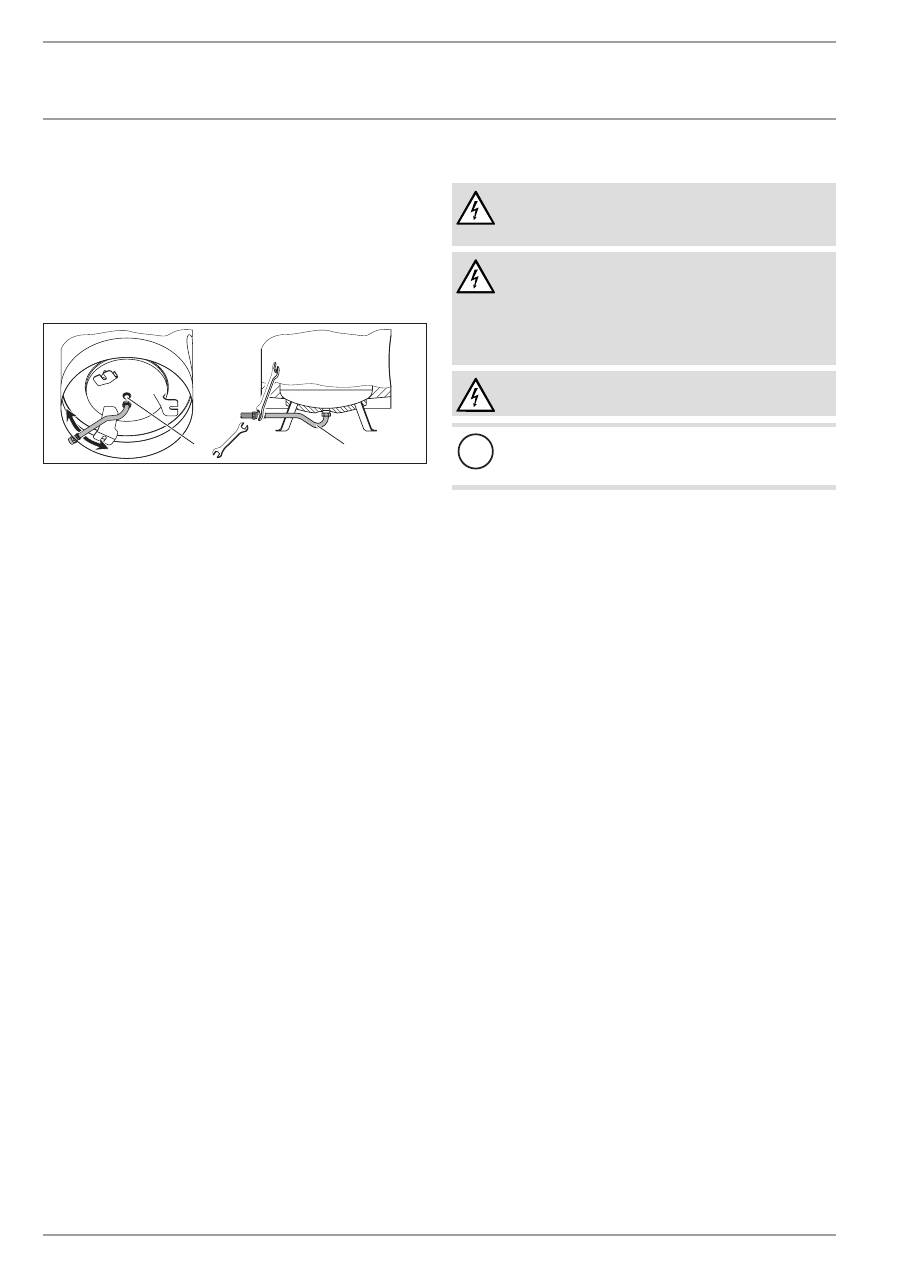
10.5 Power supply
WARNING Electrocution
Before any work on the appliance, disconnect all poles
from the power supply.
WARNING Electrocution
The connection to the power supply is only permissible
as a permanent connection in conjunction with the re-
movable cable entry. Ensure that the appliance can be
separated from the power supply by an isolator that dis-
connects all poles with at least 3 mm contact separation.
WARNING Electrocution
Ensure that the appliance is earthed.
!
Material damage
Observe the type plate. The specified voltage must match
the mains voltage.
f
f
Pull off the temperature selector.
f
f
Undo the screws at the bottom of the control panel cover and
remove the cover.
f
f
Prepare the power cable and feed it through the cable grom-
met into the control panel. Select a cable with a cross-section
suited to the load of the appliance.
f
f
Connect the required load in accordance with the connection
examples (see chapter "Specification / Wiring diagrams and
connections").
f
f
Fit the control panel cover.
f
f
Push on the temperature selector.
f
f
If the power supply utility does not permit rapid heating,
cover the pushbutton with the plastic cap provided.
f
f
Use a ballpoint pen to mark the selected connected load and
voltage on the type plate.
www.stiebel-eltron.com
SHW S |
23
EN
GL
ISH
InStallatIOn
commissioning
11. commissioning
11.1 commissioning
f
f
Open a draw-off point until the appliance has filled up and
the pipework is free of air.
f
f
Adjust the flow rate. For this, observe the maximum permis-
sible flow rate with a fully opened tap (see chapter "Specifi-
cation / Data table"). If necessary reduce the flow rate at the
butterfly valve of the safety assembly.
f
f
Carry out a tightness check.
f
f
Turn the temperature selector to maximum temperature.
f
f
Switch the mains power ON.
f
f
Check the function of the appliance.
f
f
Check the function of the safety assembly.
11.1.1 appliance handover
f
f
Explain the appliance function to users and familiarise them
with its operation.
f
f
Make the user aware of potential dangers, especially the risk
of scalding.
f
f
Hand over these instructions.
11.2 recommissioning
See chapter "Commissioning".
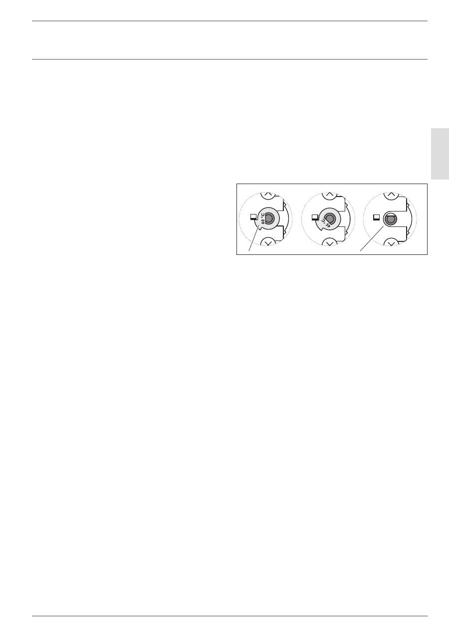
12. settings
12.2.1 limiting the temperature selection
You can adjust the temperature selection limitation beneath the
temperature selector.
Factory setting: Limited to 60 °C
f
f
Set the temperature selector to "cold" and isolate the appli-
ance from the power supply.
f
f
Remove the temperature selector and the control panel
cover.
1
2
26
�0
2�
79
�0
07
0
1 Limiter disc
2 Without limiter disc, maximum 82 °C
f
f
You can set the limit to 45 °C / 60 °C by rotating the limiter
disc. After removing the limiter disc, the maximum tempera-
ture can be set.
f
f
Replace the control panel cover and temperature selector.
13. shutting down
f
f
Disconnect the appliance from the mains at the MCB/fuse in
the fuse box.
f
f
Drain the appliance. See chapter "Maintenance / Draining the
appliance".
24
| SHW S www.stiebel-eltron.com
InStallatIOn
troubleshooting
14. troubleshooting
Note
The high limit safety cut-out can respond at temperatures
below –15 °C. The appliance may be subjected to these
temperatures during storage or transport.
Fault
cause
Remedy
The water does not
heat up.
The high limit safety
cut-out has responded
because the controller is
faulty.
Replace the thermostat
and press the high limit
safety cut-out reset but-
ton.
The high limit safety cut-
out has responded be-
cause the temperature has
dropped below -15 °C.
Press the reset button.
A heating element is
faulty.
Replace the flanged im-
mersion heater.
Rapid heating does not
switch on.
Check the contactor and
replace if required.
The safety valve drips
when the heating is
switched off.
The valve seat is contam-
inated.
Clean the valve seat.
26
�0
2�
09
�0
07
0�
1
1 High limit safety cut-out reset button
15. maintenance
WARNING Electrocution
Carry out all electrical connection and installation work
in accordance with relevant regulations.
WARNING Electrocution
Before any work on the appliance, disconnect all poles
of the appliance from the power supply.
If you need to drain the appliance, observe chapter "Draining the
appliance".
15.1 checking the safety valve
f
f
Regularly vent the safety valve on the safety assembly until a
full water jet is discharged.
15.2 draining the appliance
WARNING Burns
Hot water may escape during the draining process.
If the cylinder needs to be drained for maintenance or to protect
the whole installation when there is a risk of frost, proceed as
follows:
f
f
Close the shut-off valve in the cold water line.
f
f
Open the hot water taps on all draw-off points.
f
f
Drain the appliance via the safety assembly.
15.3 replacing the signal anode
f
f
Replace the signal anode if it becomes depleted.
15.4 cleaning and descaling the appliance
f
f
Never use descaling pumps.
f
f
Only descale the flanged immersion heater after dismantling
and never treat the cylinder surface or protective anode with
descaling agents.
Torque of the flange screws: see chapter "Specification / Dimen-
sions and connections"
15.5 replacing flanged immersion heater
26
�0
2�
09
�0
06
9�
5
6
4
2
3
1
1 Insulation plate
2 Flange plate
3 Soldered flange
4 Insulating plate
5 Corrosion resistor 390 Ω
6 Gasket
The corrosion resistor acts to balance the potential and prevents
power leakage corrosion on the heating elements.
f
f
Never damage or remove the corrosion resistor during
maintenance.
f
f
After replacing the corrosion resistor, reassemble the flanged
immersion heater correctly.
www.stiebel-eltron.com
SHW S |
25
EN
GL
ISH
InStallatIOn
Specification
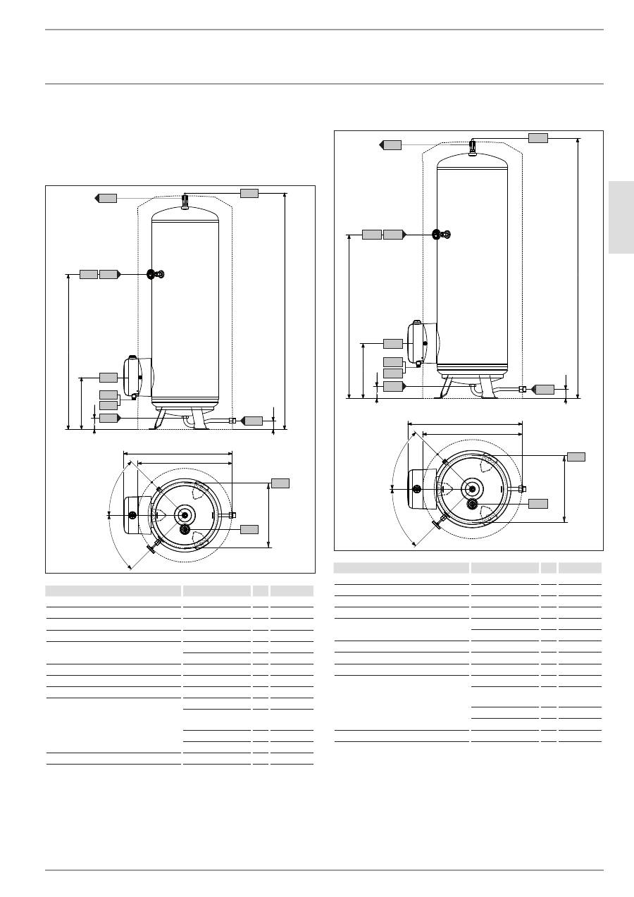
16. specification
16.1 dimensions and connections
sHw 200 s
430
a43
60
80
1578
340
1035
730
630
h43
i01
i18
i18
c03
c06
c01
c10
b02
b03
45°
45°
D
00000
17
59
2
SHW 200 S
a43 Pitch circle diameter of feet
b02 Entry electrical cables I
Diameter
PG 16
b03 Entry electrical cables II
Diameter
PG 13.5
c01 Cold water inlet
Male thread
G 1 A
c03 Cold water inlet pipe
Male thread
G 1 A
Torque
Nm
100
c06 DHW outlet
Male thread
G 1 A
c10 DHW circulation
Male thread
G 1/2 A
h43 Thermometer
Diameter
mm
14.5
i01 Flange
Diameter
mm
210
Pitch circle diam-
eter
mm
180
Screws
10 x M12
Torque
Nm
55
i18 Protective anode
Female thread
G 1 1/4
sHw 300 s
75
55
1593
365
1040
815
700
i18
i18
c03
45°
45°
h43
i01
c01
c10
b02
b03
490
a43
c06
D
00000
17
59
3
SHW 300 S
a43 Pitch circle diameter of feet
b02 Entry electrical cables I
Diameter
PG 16
b03 Entry electrical cables II
Diameter
PG 13.5
c01 Cold water inlet
Male thread
G 1 A
c03 Cold water inlet pipe
Male thread
G 1 A
Torque
Nm
100
c06 DHW outlet
Male thread
G 1 A
c10 DHW circulation
Male thread
G 1/2 A
h43 Thermometer
Diameter
mm
14.5
i01 Flange
Diameter
mm
210
Pitch circle diam-
eter
mm
180
Screws
10 x M12
Torque
Nm
55
i18 Protective anode
Female thread
G 1 1/4
26
| SHW S www.stiebel-eltron.com
InStallatIOn
Specification
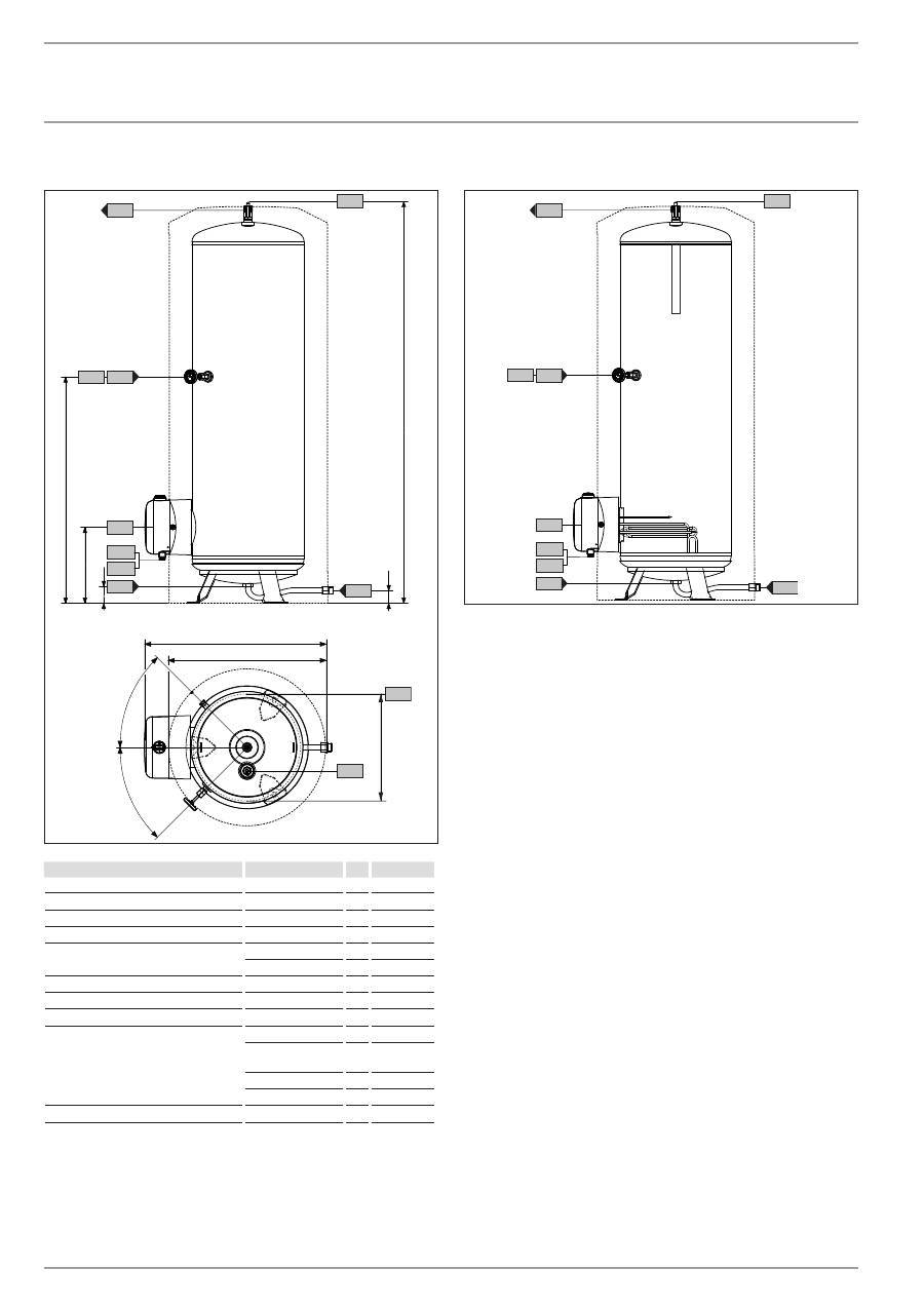
sHw 400 s
75
55
1763
375
1160
865
750
i18
i18
c03
45°
45°
h43
i01
c01
c10
b02
b03
540
a43
c06
D
00000
17
59
4
SHW 400 S
a43 Pitch circle diameter of feet
b02 Entry electrical cables I
Diameter
PG 16
b03 Entry electrical cables II
Diameter
PG 13.5
c01 Cold water inlet
Male thread
G 1 A
c03 Cold water inlet pipe
Male thread
G 1 A
Torque
Nm
100
c06 DHW outlet
Male thread
G 1 A
c10 DHW circulation
Male thread
G 1/2 A
h43 Thermometer
Diameter
mm
14.5
i01 Flange
Diameter
mm
210
Pitch circle diam-
eter
mm
180
Screws
10 x M12
Torque
Nm
55
i18 Protective anode
Female thread
G 1 1/4
appliance sectional view
i18
c03
h43
i01
c01
c10
b02
b03
c06
D
00000
35
57
6
www.stiebel-eltron.com
SHW S |
27
EN
GL
ISH
InStallatIOn
Specification
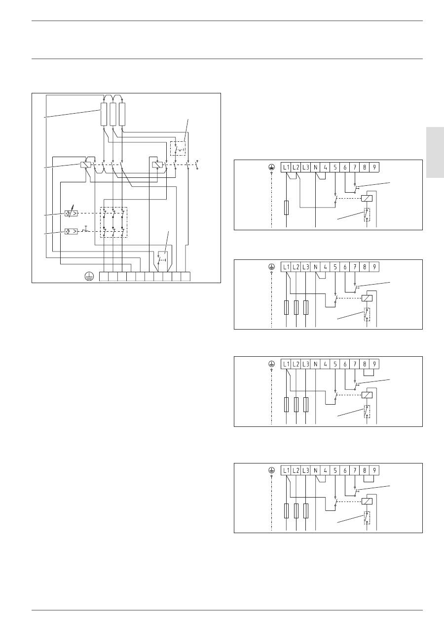
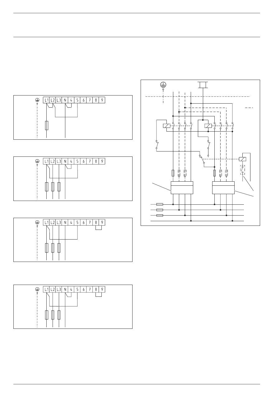
16.2 wiring diagrams and connections
L1 L2 L3 N 4 5 6 7 8 9
1
II
3
I
2
2
1
5
4
3
6
26
�0
2�
79
�0
06
0
1 Circuit breaker in the control panel
2 Pushbutton for rapid heating
3 High limit safety cut-out
4 Temperature controller
5 Contactor
6 Heating element, 2 kW ~ 230 V each
dual circuit operation, single meter measurement with power
supply utility contact
In the following connection examples, the rapid heating output
during peak tariff periods is given after the forward slash.
Note the position of the circuit breaker in the control panel.
2/4 kW
Switch position I
1/N/PE ~ 230 V
4/4 kW
Switch position Il
1/N/PE ~ 230 V
2
1
26
�0
2�
79
�0
06
1
2/6 kW
Switch position I
3/N/PE ~ 400 V
2
1
26
�02
�7
9�
00
62
3/6 kW
Switch position I
3/N/PE ~ 400 V
2
1
26
�0
2�
79
�0
06
3
4/6 kW
Switch position I
3/N/PE ~ 400 V
6/6 kW
Switch position Il
3/N/PE ~ 400 V
2
1
26
�0
2�
79
�0
06
4
1 Pushbutton for rapid heating
2 Power supply utility contact
28
| SHW S www.stiebel-eltron.com
InStallatIOn
Specification
single circuit operation
In the following connection examples, the output of the rapid
heater is given in brackets.
Note the position of the circuit breaker in the control panel.
2(4) kW
Switch position I
1/N/PE ~ 230 V
4(4) kW
Switch position Il
1/N/PE ~ 230 V
26
�0
2�
79
�0
06
5
2(6) kW
Switch position I
3/N/PE ~ 400 V
26
�0
2�
79
�0
06
6
3(6) kW
Switch position I
3/N/PE ~ 400 V
26
�0
2�
79
�0
067
4(6) kW
Switch position I
3/N/PE ~ 400 V
6(6) kW
Switch position Il
3/N/PE ~ 400 V
26
�0
2�
79
�0
06
8
dual circuit operation, dual meter measurement with power
supply utility contact
1/N/PE ~ 230 V
3/N/PE ~ 400 V
5
PE
K1
K2
K2
K1
L1
N
L3
L2
26
�0
2�
79
�0
06
9
3
2
1
4
K1 Contactor 1
K2 Contactor 2
1 Connections also required for 3/N/PE ~ 400 V
2 Power supply utility contact
3 Off-peak tariff meter
4 Peak tariff meter
Ensure connection to the same phase.
www.stiebel-eltron.com
SHW S |
29
EN
GL
ISH
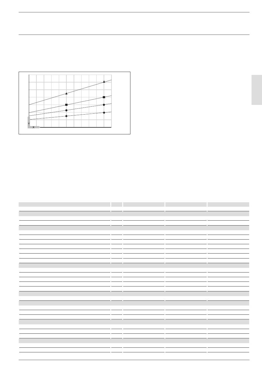
16.3 Heat-up diagram
The heat-up time depends on the cylinder capacity, cold water
inlet temperature and heating output.
At 10 °C cold water temperature and temperature setting "E":
400
300
2
4
6
8
10
12
2
3
4
1
84
�0
2�
02
�0
01
6
X Nominal capacity [I]
Y Duration [h]
1 2 kW
2 3 kW
3 4 kW
4 6 kW
16.4 Fault conditions
In the event of a fault, temperatures of up to 95 °C at 0.6 MPa
can occur.
16.5 data table
SHW 200 S
SHW 300 S
SHW 400 S
182120
182121
182122
Hydraulic data
Nominal capacity
l
200
300
400
Amount of mixed water 40 °C (15 °C/60 °C)
l
397
590
780
Electrical data
Connected load ~ 230 V
kW
2-4
2-4
2-4
Connected load ~ 400 V
kW
2-6
2-6
2-6
Rated voltage
V
230/400
230/400
230/400
Phases
1/N/PE,3/N/PE
1/N/PE,3/N/PE
1/N/PE,3/N/PE
Frequency
Hz
40-450
40-450
40-450
Single circuit operating mode
X
X
X
Dual circuit operating mode
X
X
X
Application limits
Temperature setting range
°C
35-82
35-82
35-82
Max. permissible pressure
MPa
0.6
0.6
0.6
Test pressure
MPa
0.78
0.78
0.78
Max. permissible temperature
°C
95
95
95
Max. flow rate
l/min
30
38
45
Energy data
Standby energy consumption/24 h at 65 °C
kWh
1.5
1.9
2.25
Versions
IP rating
IP24
IP24
IP24
Sealed unvented type
X
X
X
Colour
pure white/basalt grey
pure white/basalt grey
pure white/basalt grey
Dimensions
Height
mm
1578
1593
1763
Width
mm
630
700
750
Depth
mm
730
815
865
Weight
Weight, full
kg
265
277
490
Weight, empty
kg
65
77
90
WaRRanty | envIROnMent and RecyclIng
Warranty
The warranty conditions of our German companies do not
apply to appliances acquired outside of Germany. In countries
where our subsidiaries sell our products, it is increasingly the
case that warranties can only be issued by those subsidiaries.
Such warranties are only granted if the subsidiary has issued
its own terms of warranty. No other warranty will be granted.
We shall not provide any warranty for appliances acquired in
countries where we have no subsidiary to sell our products.
This will not affect warranties issued by any importers.
Environment and recycling
We would ask you to help protect the environment. After use,
dispose of the various materials in accordance with national
regulations.
InStallatIOn | WaRRanty | envIROnMent and RecyclIng
Specification
