Stiebel Eltron RTF Z 13.05.2006 - 28.02.2009: инструкция
Раздел: Климатическое Оборудование
Тип: Радиатор
Инструкция к Радиатору Stiebel Eltron RTF Z 13.05.2006 - 28.02.2009
M
+
–
OK
6
9
3
15
21
S1
Mo - Fr
Sa - So
S1
E1
E1
S2
S3
E2
E3
E1
E2
S1
S2
P1
P2
P3
12
18
24
Uhrzeit
Komforttemperatur
sonst Absenktemperatur
Pr
ogramme
6
00
6
00
12
00
9
00
9
00
14
00
16
00
17
00
23
00
23
00
23
00
7
00
1 2 3 4 5
6
6
12
18
24
0
7
P
2
P
2
S
1
S
1
P
2.5
RTF-Z
Fußboden-Temperaturregler
Gebrauchs- und Montageanweisung
Technik zum Wohlfühlen
185582
5 21 177
03
1. Gebrauchsanweisung
für den Benutzer und den Fachmann
Die Nutzung elektrischer Geräte muss
grundsätzlich mit der gebotenen Vorsicht er-
folgen, um ein potentielles Risiko durch Feuer,
elektrischen Stromschlag oder Verletzung
auszuschließen. Daher ist das Gerät nur wie
in dieser Anweisung beschrieben zu nutzen.
Jeder Gebrauch außerhalb der Hersteller-
empfehlung kann zu Schäden, Brand, Strom-
schlag oder Verletzung führen.
Vor Gebrauch des Reglers ist die gesamte
Anweisung zu lesen und die enthaltenen Hin-
weise zum sachgemäßen Umgang mit dem
Gerät sind zu befolgen.
Diese Anweisung sorgfältig aufbewah-
ren, bei Besitzerwechsel des Reglers
dem Nachfolger aushändigen.
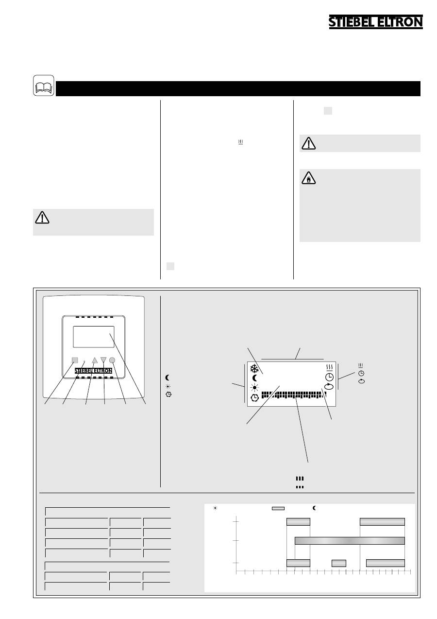
Gerätebeschreibung
Der RTF-Z mit digitaler Wochenschaltuhr dient
zur individuellen Regelung von Fußboden-
temperierungen. Hierfür kann zwischen 4 Be-
triebsarten gewählt werden.
Mit Anschluss des Reglers an das Stromnetz
wird dieser automatisch eingeschaltet und re-
gelt die Fußbodentemperierung auf den
werkseitig eingestellten Wert der Komfort-
temperatur (das Aufheizen ist durch das Funk-
tionssymbol „Heizbetrieb“ zu erkennen).
Nach Einstellen der Uhrzeit schaltet der Reg-
ler automatisch in die Betriebsart „Uhren-
programm“ um (Schaltzeiten siehe Diagramm).
Durch eine Selbstlernfunktion des RTF-Z wird
im Uhrenprogramm mit der Startzeit direkt der
Zeitpunkt eingegeben, ab dem die Komfort-
temperatur erreicht sein soll. Der Beginn der
Heizzeit liegt damit vor der eingestellten
Startzeit.
Die Selbstlernfunktion ist werkseitig aktiviert,
kann aber im Justagemodus deaktiviert werden.
Gerät aus-/einschalten
Zum Ausschalten des Reglers muss die Taste
M
3 Sekunden lang gedrückt werden. Im
Display wird „OFF“ angezeigt.
Zum wieder Einschalten des Reglers muss
die Taste
M
erneut gedrückt werden. Der
Regler kehrt in die zuletzt aktive Betriebsart
zurück.
Bei ausgeschaltetem Regler
kein
Frostschutzbetrieb!
Sicherheitshinweise
Der Regler darf nicht betrieben werden
– in Räumen, die durch Chemikalien, Staub,
Gase oder Dämpfe feuer- oder
explosionsgefährdet sind;
– in unmittelbarer Nähe von Leitungen
oder Behältnissen, die brennbare oder
explosionsgefährdete Stoffe führen oder
enthalten.
Ist der Regler beschädigt, heruntergefallen
oder es liegt bereits eine Fehlfunktion vor, ist
das Gerät nicht in Betrieb zu nehmen.
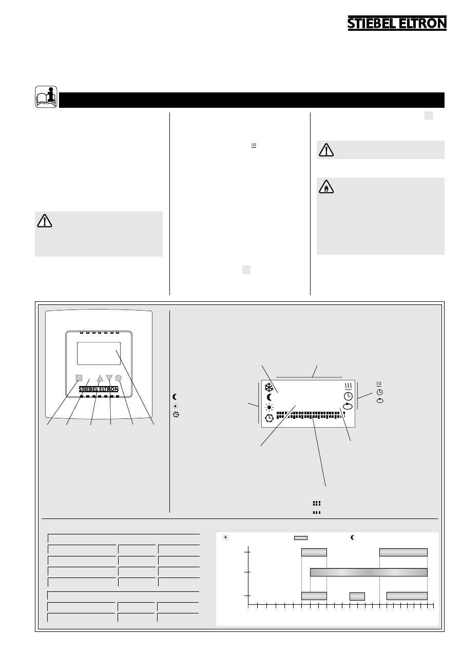
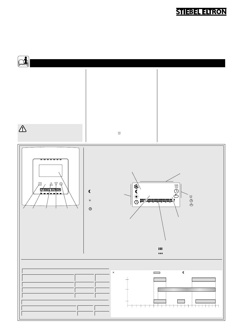
1
M
enü – Auswahl einer Betriebsart oder
Funktion durch wiederholtes Drücken
2
Reset – Wiederherstellung der Werksein-
stellung. Versenkte Taste mit nicht leiten-
dem stumpfen Gegenstand kurz drücken.
3
Erhöhen des Einstellwertes
4
Vermindern des Einstellwertes
5
Bestätigen des Einstellwertes
6
Display
1
2
3
4
5
6
8966.02
8967.01
Funktionen
Heizbetrieb
Uhrzeit
P
Programmwahl
Uhrenprogramme
P1 = Programm 1
P2 = Programm 2
P3 = Programm 3
Betriebsarten
7
Frostschutz
Absenktemperatur
Komforttemperatur
Uhrenprogramm
Wochentage
1-5 = Montag - Freitag
6+7 = Samstag + Sonntag
Start-/Endzeit im Uhrenprogramm
S1 = 1. Startzeit
E1 = 1. Endzeit
S2 = 2. Startzeit
E2 = 2. Endzeit
S3 = 3. Startzeit
E3 = 3. Endzeit
Wertangabe
Sollwert
Boden
temperatur
(Merkziffer, z. B.
2.5
= ca. 25 °C)
oder
Uhrzeit
Zeitsegmente der Schaltuhr
Komforttemperatur
Absenktemperatur
Werkseinstellungen
Bodentemperaturen der Betriebsarten
Frostschutz
1.0
=
^ ca. 10
Merkziffer
°C
Absenktemperatur
1.8
=
^ ca. 18
Komforttemperatur
2.5
=
^ ca. 25
Temperatureinstellgrenzen
max. Bodentemp.
4.0
=
^ ca. 40
min. Bodentemp.
1.0
=
^ ca. 10
Display-Anzeigen
i
2
oder
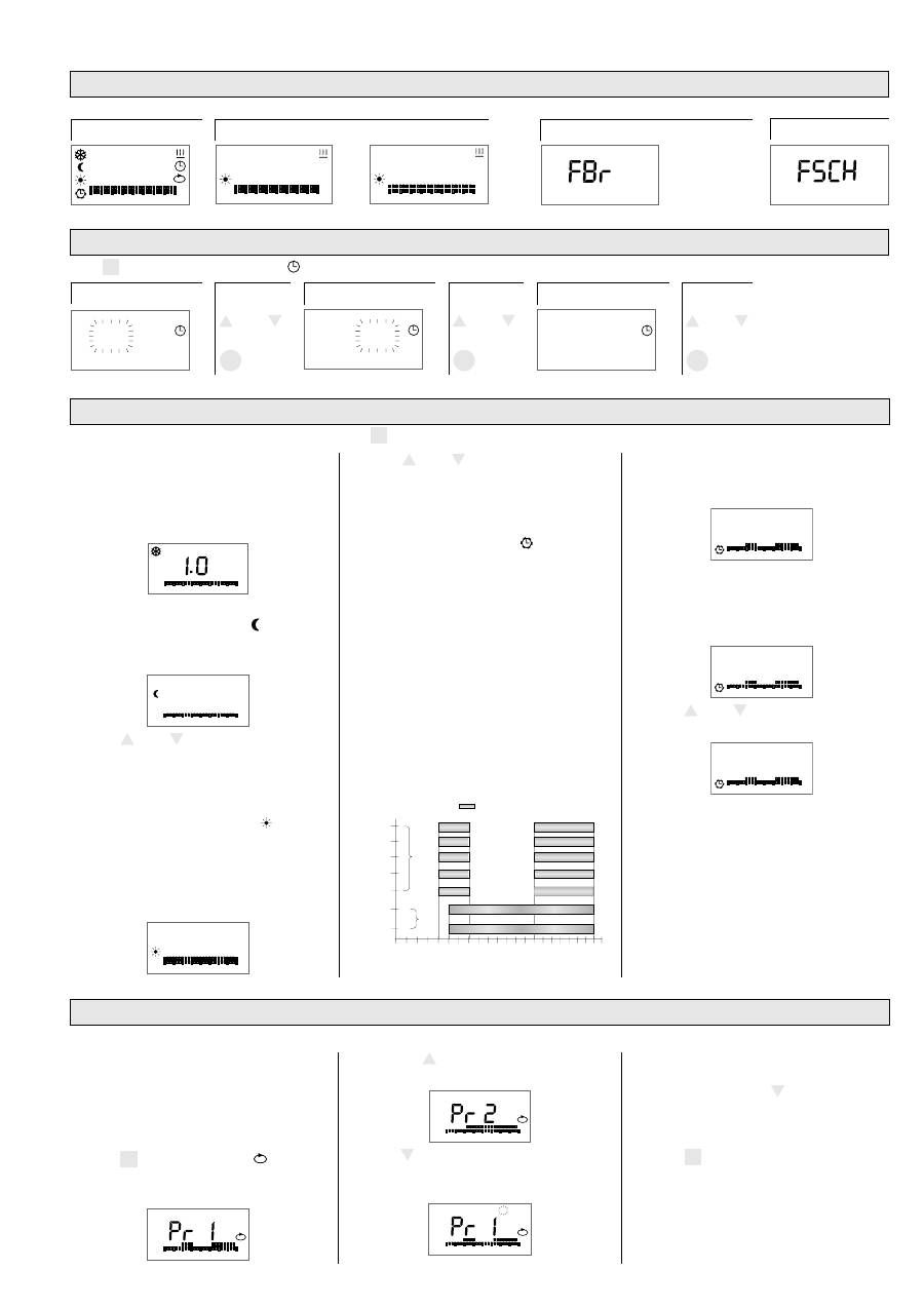
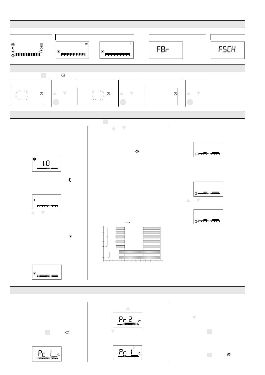
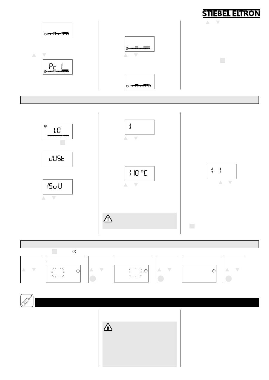
1.1 Erstinbetriebnahme
Nach Anschluss an das Stromnetz erscheinen folgende Anzeigen:
für ca. 5 Sekunden . . .
. . . danach abwechselnd
Fühler defekt oder nicht angeschlossen
1.2 Ersteinstellung Uhrzeit und Wochentag
Taste
M
drücken bis Funktionssymbol angezeigt wird.
Stunde
Tasten
+
oder
–
Minuten
Tasten
Wochentag
+
oder
–
Tasten
OK
OK
OK
6
12
18
24
0
2.5
6
12
18
24
0
6
12
18
24
0
6
12
18
24
0
00:00
1 2 3 4 5
6
6
12
18
24
0
7
8
8
8
8
8
8
8
8
P
88:88
00
:00
00
:00
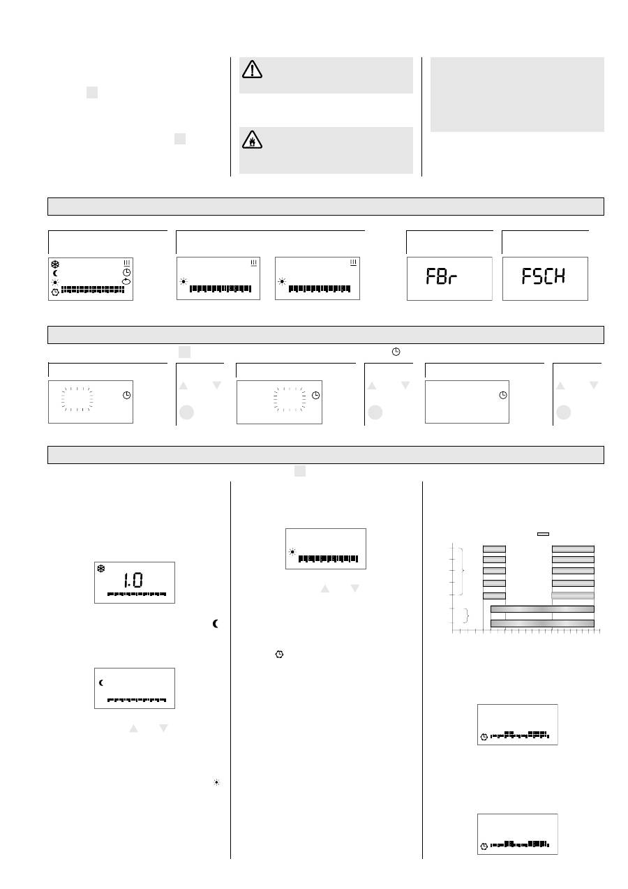
1.3 Betriebsarten
1.4 Uhrenprogramm verändern
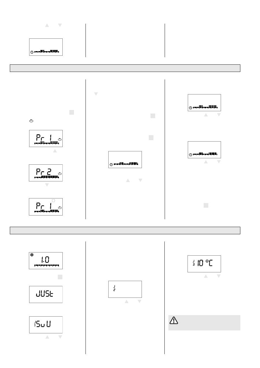
1.3.1 Frostschutz
7
Nicht veränderbarer Sollwert
(Anzeige
1.0
),
wird bei einer Bodentemperatur von ca.
10 °C aktiv. Alle Anzeigen außer Frostschutz-
symbol gehen nach ca. 20 Sekunden aus.
1
6
12
18
24
0
1.3.2 Absenktemperatur
Reduzierter Wert gegenüber der Komfort-
temperatur, z. B. während der Nachtzeit.
1
6
12
18
24
0
1.8
⇒
Taste
+
oder
–
drücken um Sollwert zu
verändern. Mit Taste
OK
bestätigen, sonst
wird nach 20 Sekunden der bisherige
Wert wieder gültig.
1.3.3 Komforttemperatur
Hier wird die während der Hauptnutzungs-
zeit bevorzugte Bodentemperatur eingestellt.
Der Regler hält in dieser Betriebsart durch
intermittierendes Heizen die Bodentempe-
ratur auf den eingestellten Wert.
1
6
12
18
24
0
2.5
⇒
Taste
+
oder
–
drücken um Sollwert zu
verändern. Mit Taste
OK
bestätigen, sonst
wird nach 20 Sekunden der bisherige
Wert wieder gültig.
1.3.4 Uhrenprogramm
Über die Zeitschaltuhr ist jeder Wochentag
einem Zeitprogramm zum automatischen
Umschalten zwischen Komfort- und Absenk-
temperatur zugeordnet.
Hierzu stehen 3 Zeitprogramme mit einer
festgelegten Anzahl von Schaltungen während
des Tages zur Verfügung, deren Schaltzeiten
individuell eingestellt werden können:
Programm 1 (P1):
2 Schaltungen
Programm 2 (P2):
1 Schaltung
Programm 3 (P3):
3 Schaltungen
Werkseitig sind folgende Schaltzeiten pro
Woche eingestellt (Wechsel zwischen Kom-
fort-/Absenktemperatur):
6
3
9
15
21
Mo
P1
S1
E1
S2
E2
S1
E1
S2
E2
S1
E1
S2
E2
S1
E1
S2
E2
S1
E1
S2
E2
E1
E1
S1
S1
P2
Mi
Fr
1
3
5
Di
Do
Sa
So
2
4
6
7
12
18
24
Uhrzeit
Komforttemperatur
W
ochentag
6
00
7
00
23
00
9
00
16
00
23
00
Tagesprogramm zuordnen
Jedem Wochentag muss ein Programm zuge-
ordnet werden, es gibt keinen Tag ohne Pro-
grammzuweisung. Um einen Tag aus einem
Programm zu entfernen, muss dieser Tag ei-
nem anderen Programm zugeordnet werden.
⇒
Taste
M
drücken bis Symbol
P
,
Pr 1
(Programm 1) und die dem Programm
zugeordneten Tage angezeigt werden;
1
6
12
18
24
0
P
2 3 4 5
⇒
Mit Taste
+
zwischen den Programmen
(Pr 2, Pr 3, Pr 1, . . .) wechseln;
6
6
12
18
24
0
7
P
⇒
Taste
–
drücken, um die dem angewählten
Programm
nicht zugewiesenen
Tage blin-
kend anzuzeigen;
1
6
12
18
24
0
P
2 3 4 5
6
⇒
Taste
OK
drücken, um den angewählten
Tag dem angewählten Programm hinzuzu-
fügen, oder mit Taste
–
zum nächsten
noch nicht zugewiesenen Tag wechseln;
⇒
Schritte wie beschrieben wiederholen, bis
alle Tage wie gewünscht zugeordnet sind;
⇒
Taste
M
zum beenden drücken – Anzeige
wechselt zum Frostschutzprogramm.
Die Schaltzeiten des Uhrenprogrammes können den jeweiligen Wünschen des Benutzers angepasst werden.
Zum Aufrufen der gewünschten Betriebsart die Taste
M
drücken, bis das jeweilige Symbol im Display erscheint.
1
+
oder
–
Nach dem Anwählen des Uhrenprogrammes
schaltet der Regler automatisch in das zum
aktuellen Wochentag eingestellte Programm.
1
6
12
18
24
0
P
1
P
1
S
1
S
1
2.5
Partyfunktion
Kurzzeitige Änderung der Solltemperatur
innerhalb des Uhrenprogramms bis zur
nächsten Schaltzeit.
1
6
12
18
24
0
P
1
P
1
1.8
⇒
Taste
+
oder
–
drücken, um Temperatur
kurzzeitig zu verändern;
1
6
12
18
24
24
0
P
1
P
1
2.2
⇒
Taste
OK
zum Bestätigen drücken. Das
Uhrenprogramm ist jetzt bis zur nächsten
Schaltzeit mit geänderter Temperatur gültig.
Fühlerkurzschluss
3
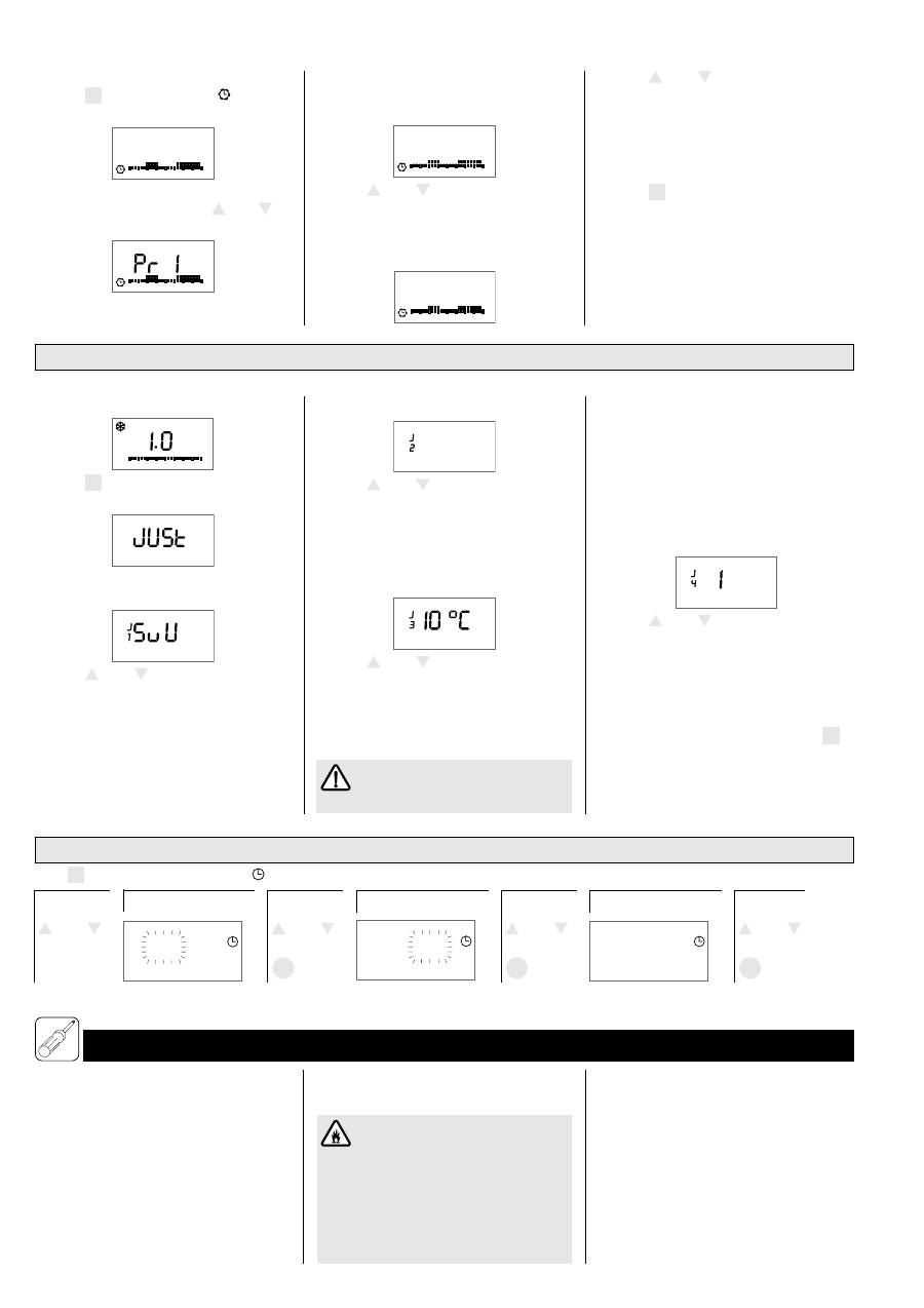
1.5 Justage
(kann nur im Frostschutzbetrieb eingestellt werden)
⇒
Betriebsart Frostschutz
7
wählen;
1
6
12
18
24
0
⇒
Taste
M
und
OK
gleichzeitig 3 Sekunden
drücken bis
„Just“
angezeigt wird;
Anzeigeneinstellung
⇒
Taste
+
oder
–
drücken, um Anzeigen-
art auszuwählen
S
= Sollwert
U
= Uhrzeit
SuU = Sollwert und Uhrzeit alle 5
Sekunden abwechselnd;
⇒
Taste
OK
zum bestätigen und wechseln
zur nächsten Justageeinstellung drücken.
Maximale Bodentemperatur
40 °c
⇒
Taste
+
oder
–
drücken, um die maxi-
mal einstellbare Bodentemperatur einzu-
stellen;
⇒
Taste
OK
zum bestätigen und wechseln
zur nächsten Justageeinstellung drücken.
Minimale Bodentemperatur
⇒
Taste
+
oder
–
drücken, um die minimal
einstellbare Bodentemperatur einzustellen
(Differenz zwischen min. und max. Boden-
temperatur mindestens 5 °C, bei Unter-
schreitung wird Maximalwert automatisch
angepasst;
Die minimale Bodentemperatur hat
keinen Einfluss auf die Betriebsart
„Frostschutz“.
Individuelle Einstellungen von Betriebsparametern, die auch bei Netzausfall gespeichert bleiben.
Programmschaltzeiten
⇒
Taste
M
drücken bis Symbol angezeigt
wird;
1
6
12
18
24
0
P
1
P
1
S
1
S
1
2.5
⇒
Taste
OK
drücken, um in den Programmier-
modus zu wechseln, mit Taste
+
oder
–
das
zu ändernde Schaltprogramm auswählen;
6
12
18
24
0
⇒
Taste
OK
drücken um zur 1. Startzeit (S1)
des ausgewählten Programms zu wech-
seln;
6
12
18
24
0
P
1
P
1
S
1
S
1
06.00
⇒
Taste
+
oder
–
zum einstellen der Start-
zeit (15min-Schritte) drücken;
⇒
Taste
OK
drücken um zur 1. Endzeit (E1)
des ausgewählten Programms zu wech-
seln;
6
12
18
24
0
P
1
P
1
E
1
E
1
09.00
⇒
Taste
+
oder
–
zum einstellen der End-
zeit (15min-Schritte) drücken;
⇒
Taste
OK
drücken um zur 2. Startzeit (S2)
des ausgewählten Programms zu wechseln;
⇒
Schritte wie beschrieben wiederholen, bis
alle Start- und Endzeiten wie gewünscht
zugeordnet sind,
⇒
Taste
M
zum beenden des Einstell-
programms drücken und zum Uhren-
programm zurückzukehren.
⇒
Taste
OK
zum bestätigen und wechseln
zur nächsten Justageeinstellung drücken.
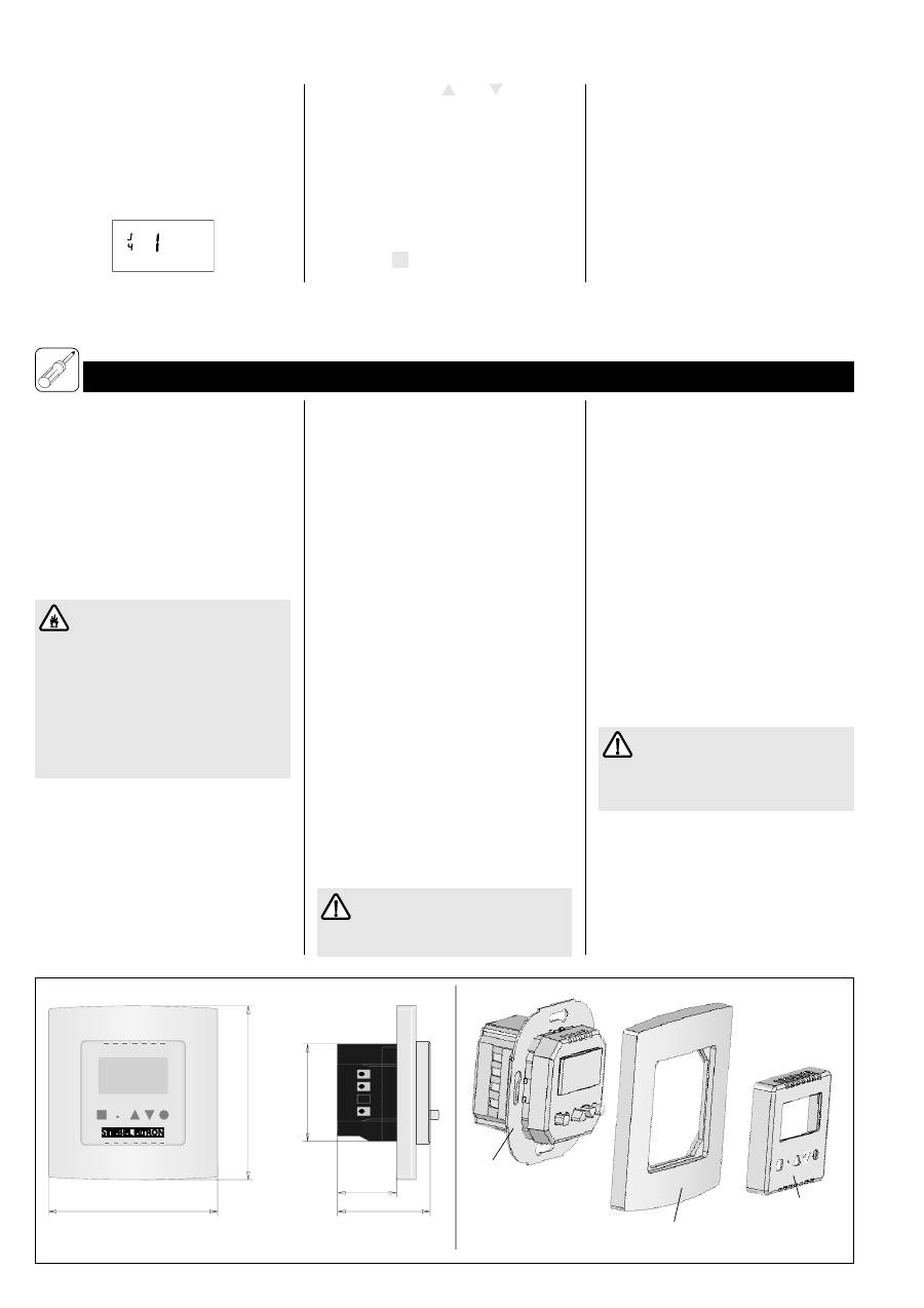
Selbstlernfunktion
Ist die Selbstlernfunktion aktiviert, schaltet
der RTF-Z die Fußbodentemperierung auto-
matisch so ein, dass die Komforttemperatur
bereits zu den eingestellten Startzeiten er-
reicht wird.
⇒
Taste
+
oder
–
drücken, um die Selbst-
lernfunktion zu aktivieren (Anzeige „
1
“)
oder deaktivieren (Anzeige „
0
“).
Wird die Selbstlernfunktion deaktiviert,
bedeuten die eingestellten Startzeiten im
Uhrenprogramm den Beginn der Heizzeit;
⇒
Taste
OK
drücken, um zur Anzeigenein-
stellung zurück zu kehren oder Taste
M
zum beenden des Justagemodus drücken.
2. Montageanweisung
für den Fachmann
Die Montage (Elektroinstallation) sowie die
Erstinbetriebnahme dieses Gerätes dürfen
nur von einem zugelassenen Fachhandwerker
entsprechend dieser Anweisung ausgeführt
werden.
Verpackung erst am Aufstellort entfernen,
dabei beachten, dass keine Zubehörteile im
Verpackungsmaterial zurückbleiben.
2.1 Vorschriften und Bestim-
mungen
Der Regler darf nicht betrieben werden
– in Räumen, die durch Chemikalien, Staub,
Gase oder Dämpfe feuer- oder explosions-
gefährdet sind;
– in unmittelbarer Nähe von Leitungen
oder Behältnissen, die brennbare oder
explosionsgefährdete Stoffe führen oder
enthalten.
•
Alle elektrischen Anschluss- und Installations-
arbeiten sind nach den VDE-Bestimmungen
(0100), den Vorschriften des zuständigen
EVU’s sowie den entsprechenden nationalen
und regionalen Vorschriften auszuführen.
•
Die Angaben auf der Regler-Unterseite be-
achten!
Die angegebene Spannung muss mit der
Netzspannung übereinstimmen.
•
Bei der Installation des Reglers in Räumen
mit Badewanne und/oder Dusche ist der
Schutzbereich nach VDE 0100 Teil 701 in
1.6 Ändern/Einstellen von Uhrzeit und Wochentag im Betrieb
Taste
M
drücken bis Funktionssymbol angezeigt wird.
Stunde
Tasten
+
oder
–
Minuten
Tasten
Wochentag
+
oder
–
Tasten
OK
OK
OK
+
oder
–
08
:43
43
:
08
1
Tasten
+
oder
–
4
M
+ –
OK
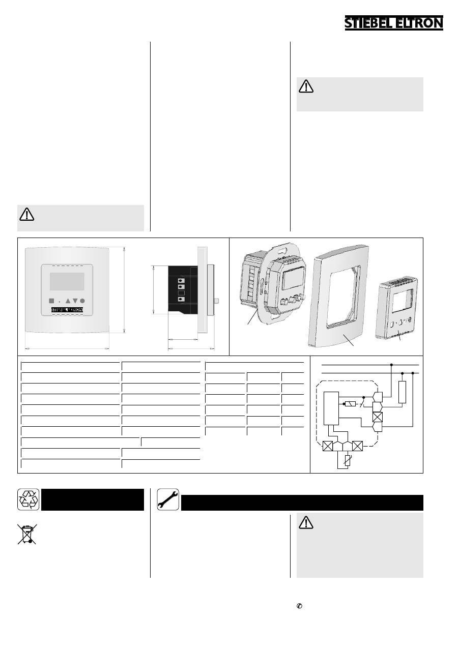
8968.02
28,5
81,5
44,5
8970.02
7
9
8
8969.02
47
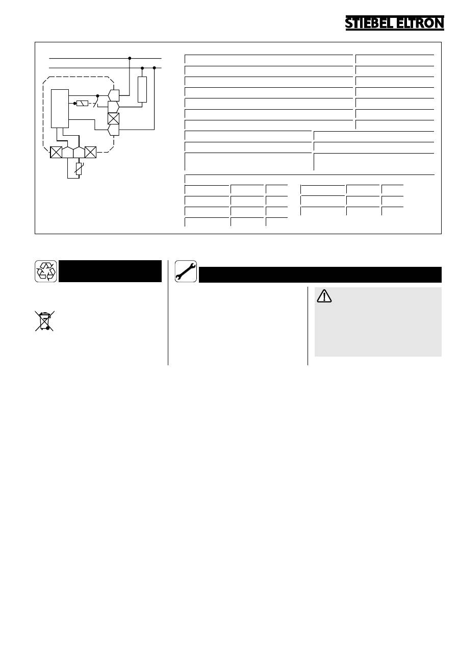
F F
LH
L
N
Elektronik
RTF-Z
L
N
FT
...
85
Fühlerkennwerte
Temperatur
R [kOhm] U [V]
20 °C
2,43
2,22
10 °C
3,66
2,49
40 °C
1,15
1,63
30 °C
1,65
1,92
50 °C
0,82
1,35
Entsorgung von Transportverpackung
Damit Ihr Gerät unbeschädigt bei Ihnen an-
kommt, haben wir es sorgfältig verpackt.
Bitte helfen Sie, die Umwelt zu schützen, und
überlassen Sie die Verpackung dem Fach-
handwerk bzw. Fachhandel.
Stiebel Eltron beteiligt sich gemeinsam mit
dem Großhandel und dem Fachhandwerk/
Fachhandel in Deutschland an einem wirksa-
men Rücknahme- und Entsorgungskonzept
für die umweltschonende Aufarbeitung der
Verpackungen.
Entsorgung von Altgeräten in Deutschland
Geräte mit dieser Kennzeichnung ge-
hören
nicht
in die Restmülltonne und
sind getrennt zu sammeln und zu
entsorgen.
Die Entsorgung dieses Altgerätes fällt
nicht
unter das Gesetz über das Inverkehrbringen,
die Rücknahme und die umweltverträgliche
Entsorgung von Elektro- und Elektronik-
geräten (Elektro- und Elektronikgerätegesetz –
ElektroG) und kann
nicht kostenlos
an den
kommunalen Sammelstellen abgegeben werden.
Das Altgerät ist fach- und sachgerecht zu ent-
sorgen. Im Rahmen des Kreislaufwirtschaft-
und Abfallgesetzes und der damit verbundenen
Produktverantwortung ermöglicht Stiebel
Eltron mit einem kostengünstigen Rücknahme-
system die Entsorgung von Altgeräten.
Fragen Sie uns oder Ihren Fachhandwerker/
Fachhändler.
Über das Rücknahmesystem werden hohe
Recyclingquoten der Materialien erreicht, um
Deponien und die Umwelt zu entlasten. Da-
mit leisten wir
gemeinsam
einen wichtigen
Beitrag zum Umweltschutz.
Bereits bei der Entwicklung neuer Geräte
achten wir auf eine hohe Recyclingfähigkeit
der Materialien.
Die Voraussetzung für eine Material-Wieder-
verwertung sind die Recycling-Symbole und die
von uns vorgenommene Kennzeichnung nach
DIN EN ISO 11469 und DIN EN ISO 1043,
damit die verschiedenen Kunststoffe getrennt
gesammelt werden können.
Entsorgung außerhalb Deutschlands
Geräte mit dieser Kennzeichnung gehören
nicht
in die Restmülltonne und sind getrennt
zu sammeln und zu entsorgen.
Die Entsorgung von Altgeräten hat fach- und
sachgerecht nach den örtlich geltenden Vor-
schriften und Gesetzen zu erfolgen.
Länge Temperaturfühler (DIN 44574)
4 m
Schaltleistung
~ 16(2) A 230 V
Typ
RTF-Z
Einstellbereich
ca. 10 ºC . . . 40 ºC
Schutzklasse
ΙΙ
, gemäß dieser Anweisung
Schaltdifferenz
1 K
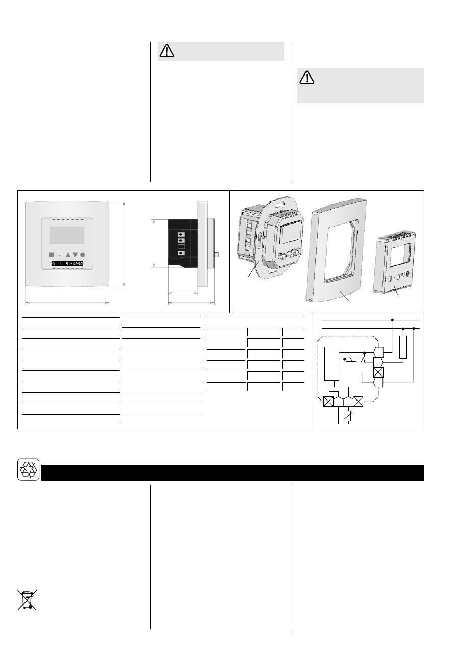
H x B x T
85 x 81,5 x 44,5 mm
Schutzart
IP 30 (nach Montage)
Gangreserve
4 Tage, nach 1h Betriebszeit
Approbationen
siehe Geräteaufdruck
3. Umwelt und Recycling
Abstimmung mit den Angaben auf dem
Geräte-Typenschild zu berücksichtigen.
•
Der Regler ist so anzubringen, dass Schalt-
und Regeleinrichtungen nicht von einer in der
Badewanne oder unter der Dusche befindli-
chen Person berührt werden können.
•
Bei Netzausfall bzw. einer Unterbrechung
oder eines Kurzschlusses der Fühlerleitung
wird die Heizung abgeschaltet..
2.2 Montage Temperaturfühler
Der Temperaturfühler ist vor dem Aufbringen
des Fußboden-Oberbelages in einem Leer-
rohr oberflächenbündig im Untergrund (z. B.
Estrich) zu versenken; vgl. Gebrauchs- und
Montageanweisung Temperiermatte.
Im Fehlerfall kann Netzspannung an
der Fühlerleitung liegen!
2.3 Montage Temperaturregler
Der Temperaturregler ist in eine handelsübli-
che UP-Schalterdosen für Geräte-Ø 55 mm
einzusetzen.
Zum Einsetzen des Temperaturreglers ist wie
folgt vorzugehen:
– Kompletten Wechselrahmen (
7, 8
) ab-
ziehen, hierzu oben und unten am Schalter-
rahmen greifen;
– Elektrischen Anschluss nach unten abgebil-
detem Schaltbild oder dem Aufdruck auf
der Rückseite der Reglerkappe vornehmen;
– Temperaturregler (
9
) in Schalterdose ein-
setzen und mit dieser verschrauben;
– Gehäusedeckel (
7
) sowie gegebenenfalls
auch den Schalterrahmen (
8
) wieder auf-
setzen;
Montage- und Gebrauchsanweisung
der Fußbodentemperierung, an die
der Raumtemperaturregler angeschlossen
werden soll, ist zu beachten.
2.4 Übergabe
Erklären Sie dem Benutzer die Funktionen
des Gerätes. Machen Sie ihn besonders auf
die Sicherheitshinweise aufmerksam.
Überreichen Sie dem Benutzer die Gebrauchs-
und Montageanweisung.
5
Garantie-Urkunde
Verkauft am: _________________________________________________
Nr.:
Garantie-Urkunde:
RTF-Z
Stempel und Unterschrift
des Fachhändlers:
4. Kundendienst und Garantie
Stand: 03/2004
Sollte einmal eine Störung an einem der Pro-
dukte auftreten, stehen wir Ihnen natürlich
mit Rat und Tat zur Seite.
Rufen Sie uns einfach unter nachfolgender
Service-Nummer an:
01803 70 20 20
(0,09 /min; Stand 3/04)
oder schreiben uns an:
Stiebel Eltron GmbH & Co. KG
- Kundendienst -
Fürstenberger Straße 77, 37603 Holzminden
E-Mail: kundendienst@stiebel-eltron.com
Telefax-Nr. 01803 70 20 25
(0,09 /min; Stand 3/04)
Weitere Anschriften sind auf der letzten Seite
aufgeführt.
Selbstverständlich hilft unser Kundendienst
auch nach Feierabend! Den Stiebel Eltron-
Kundendienst können Sie an sieben Tagen in
der Woche täglich bis 22.00 Uhr telefonisch
erreichen – auch an Sonn- und Samstagen
sowie an Feiertagen.
Im Notfall steht also immer ein Kunden-
diensttechniker für Sie bereit. Dass ein sol-
cher Sonderservice auch zusätzlich entlohnt
werden muss, wenn kein Garantiefall vorliegt,
werden Sie sicherlich verstehen.
Stiebel Eltron – Garantie für die ab
01.01.2002 gekauften Stiebel Eltron-Geräte
Diese Garantiebedingungen regeln zusätzli-
che Garantieleistungen von Stiebel Eltron ge-
genüber dem Endkunden, die neben die ge-
setzlichen Gewährleistungsansprüche des
Kunden treten. Daher werden auch gesetzli-
che Gewährleistungsansprüche des Kunden
gegenüber seinen sonstigen Vertragspartnern,
insbesondere dem Verkäufer des mit der Ga-
rantie versehenen Stiebel Eltron-Gerätes, von
dieser Garantie nicht berührt.
Diese Garantiebedingungen gelten nur für
solche Geräte, die vom Endkunden in der
Bundesrepublik Deutschland als Neugeräte
erworben werden. Ein Garantievertrag kommt
nicht zustande, soweit der Endkunde ein ge-
brauchtes Gerät oder ein neues Gerät seiner-
seits von einem anderen Endkunden erwirbt.
Inhalt und Umfang der Garantie
Stiebel Eltron erbringt die Garantieleistungen,
wenn an Stiebel Eltron Geräten ein Herstel-
lungs- und/oder Materialfehler innerhalb der
Garantiezeit auftritt. Diese Garantie umfasst
jedoch keine Leistungen von Stiebel Eltron
für solche Geräte, an denen Fehler, Schäden
oder Mängel aufgrund von Verkalkung, chemi-
scher oder elektrochemischer Einwirkung,
fehlerhafter Aufstellung bzw. Installation, so-
wie unsachgemäßer Einregulierung, Bedienung
oder unsachgemäßer Inanspruchnahme bzw.
Verwendung auftreten. Ebenso ausgeschlossen
sind Leistungen aufgrund mangelhafter oder
unterlassener Wartung, Witterungseinflüssen
oder sonstigen Naturerscheinungen.
Die Garantie erlischt, wenn an dem Gerät
Reparaturen, Eingriffe oder Abänderungen
durch nicht von Stiebel Eltron autorisierte
Personen vorgenommen wurden.
Die Garantieleistung von Stiebel Eltron um-
fasst die sorgfältige Prüfung des Gerätes, wo-
bei zunächst ermittelt wird, ob ein Garantie-
anspruch besteht. Im Garantiefall entscheidet
allein Stiebel Eltron, auf welche Art der Schaden
behoben werden soll. Es steht Stiebel Eltron
frei, eine Reparatur des Gerätes ausführen zu
lassen oder selbst auszuführen. Etwaige aus-
gewechselte Teile werden Eigentum von
Stiebel Eltron.
Für die Dauer und Reichweite der Garantie
übernimmt Stiebel Eltron sämtliche Material-
und Montagekosten, nicht jedoch zusätzliche
Kosten für die Leistungen eines Notdienstes.
Soweit der Kunde wegen des Garantiefalles
aufgrund gesetzlicher Gewährleistungsan-
sprüche gegen andere Vertragspartner Leist-
ungen erhalten hat, entfällt eine Leistungs-
pflicht von Stiebel Eltron.
Soweit Stiebel Eltron Garantieleistungen er-
bringt, übernimmt Stiebel Eltron keine Haf-
tung für die Beschädigung eines Gerätes
durch Diebstahl, Feuer, Aufruhr o. ä. Ursachen.
Über die vorstehend zugesagten Garantie-
leistungen hinausgehend kann der Endkunde
nach dieser Garantie keine Ansprüche wegen
mittelbarer Schäden oder Folgeschäden, die
durch ein Stiebel Eltron-Gerät verursacht
werden, insbesondere auf Ersatz außerhalb
des Gerätes entstandener Schäden, geltend
machen. Gesetzliche Ansprüche des Kunden
gegen Stiebel Eltron oder Dritte bleiben je-
doch unberührt.
Garantiedauer
Die Garantiezeit beträgt 24 Monate für jedes
Stiebel Eltron-Gerät, das im privaten Haushalt
eingesetzt wird, und 12 Monate für jedes
Stiebel Eltron-Gerät, welches in Gewerbebe-
trieben, Handwerksbetrieben, Industriebetrie-
ben oder gleichzusetzenden Tätigkeiten ein-
gesetzt wird. Die Garantiezeit beginnt für je-
des Gerät mit der Übergabe des Gerätes an
den Erstendabnehmer. Zwei Jahre nach Über-
Technik zum Wohlfühlen
gabe des jeweiligen Gerätes an den Erstend-
abnehmer erlischt die Garantie, soweit die
Garantiezeit nicht nach vorstehendem Absatz
12 Monate beträgt.
Soweit Stiebel Eltron Garantieleistungen er-
bringt, führt dies weder zu einer Verlänge-
rung der Garantiefrist noch wird eine neue
Garantiefrist durch diese Leistungen für das
Gerät oder für etwaige eingebaute Ersatzteile
in Gang gesetzt.
Inanspruchnahme der Garantie
Garantieansprüche sind vor Ablauf der Ga-
rantiezeit innerhalb von zwei Wochen nach-
dem der Mangel erkannt wurde, unter Angabe
des vom Kunden festgestellten Fehlers des
Gerätes und des Zeitpunktes seiner Feststel-
lung bei Stiebel Eltron anzumelden. Als Garan-
tienachweis ist die vom Verkäufer des Gerätes
ausgefüllte Garantieurkunde, die Rechnung
oder ein sonstiger datierter Kaufnachweis
beizufügen. Fehlt die vorgenannte Angabe oder
Unterlage, besteht kein Garantieanspruch.
Garantie für in Deutschland erworbene, je-
doch außerhalb Deutschlands eingesetzte
Geräte
Stiebel Eltron ist nicht verpflichtet, Garantie-
leistungen außerhalb der Bundesrepublik
Deutschland zu erbringen. Bei Störungen eines
im Ausland eingesetzten Gerätes ist dieses
gegebenenfalls auf Gefahr und Kosten des
Kunden an den Kundendienst in Deutschland
zu senden. Die Rücksendung durch Stiebel
Eltron erfolgt ebenfalls auf Gefahr und Kos-
ten des Kunden. Etwaige gesetzliche Ansprü-
che des Kunden gegen Stiebel Eltron oder
Dritte bleiben auch in diesem Fall unberührt.
Außerhalb Deutschlands erworbene Geräte
Für außerhalb Deutschlands erworbene Ge-
räte gilt diese Garantie nicht. Es gelten die
jeweiligen gesetzlichen Vorschriften und
gegebenenfalls die Lieferbedingungen der
Stiebel Eltron-Ländergesellschaft bzw. des Im-
porteurs.
Adressen und Kontakte
www.stiebel-eltron.com
Zentrale Holzminden
Stiebel Eltron GmbH & Co. KG
Dr.-Stiebel-Str.
37603 Holzminden
Telefon
0 55 31 / 7 02-0
Fax Zentrale
0 55 31 / 7 02-4 80
info@stiebel-eltron.com
Internet
www.stiebel-eltron.com
Stiebel Eltron International GmbH
Dr.-Stiebel-Str.
37603 Holzminden
Telefon
0 55 31 / 7 02-0
Fax
0 55 31 / 7 02-4 79
info@stiebel-eltron.com
Internet
www.stiebel-eltron.com
Stiebel Eltron Vertriebszentren
Dortmund
Oespel (Indupark)
Brennaborstr. 19
44149 Dortmund
Telefon
02 31 / 96 50 22-10
E-Mail: dortmund@stiebel-eltron.com
Frankfurt
Rudolf-Diesel-Str. 18
65760 Eschborn
Telefon
0 61 73 / 6 02-10
E-Mail: frankfurt@stiebel-eltron.com
Hamburg
Georg-Heyken-Straße 4a 21147 Hamburg
Telefon
0 40 / 75 20 18-10
E-Mail: hamburg@stiebel-eltron.com
Köln
Ossendorf
Mathias-Brüggen-Str. 132 50829 Köln
Telefon
02 21 / 5 97 71-10
E-Mail: koeln@stiebel-eltron.com
Leipzig
Airport Gewerbepark/Glesien
Ikarusstr. 10
04435 Schkeuditz-Glesien
Telefon
03 42 07 / 7 55-10
E-Mail: leipzig@stiebel-eltron.com
München
Hainbuchenring 4
82061 Neuried
Telefon
0 89 / 89 91 56-10
E-Mail: muenchen@stiebel-eltron.com
Stuttgart
Weilimdorf
Motorstr. 39
70499 Stuttgart
Telefon
07 11 / 9 88 67-10
E-Mail: stuttgart@stiebel-eltron.com
Tochtergesellschaften und Vertriebs-
zentren Europa und Übersee
Belgique
Stiebel Eltron Sprl / Pvba
Rue Mitoyenne 897
B-4840 Welkenraedt
087-88 14 65
Fax 087-88 15 97
info@stiebel-eltron.be
Internet
www.stiebel-eltron.be
C
∨∨∨∨∨
eská republika
Stiebel Eltron spol. s r.o.
K Háju
o
oo
oo
m 946
C
∨∨∨∨∨
Z-15500 Praha 5-Stodulky
2-511 16 111
Fax 2-355 12 122
info@stiebel-eltron.cz
Internet
www.stiebel-eltron.cz
France
Stiebel Eltron S.A.S.
7-9, rue des Selliers
B.P. 85107
F-57073 Metz-Cédex
03-87-74 38 88
Fax 03-87-74 68 26
info@stiebel-eltron.fr
Internet
www.stiebel-eltron.fr
Great Britain
Exclusive Distributor:
Applied Energy Products Ltd.
Morley Way
GB-Peterborough PE2 9JJ
08709-000420
Fax 01733-319610
sales@applied-energy.com
Internet
www.applied-energy.com
Magyarország
Stiebel Eltron Kft.
Pacsirtamezo´´
u.
41
H-1036 Budapest
012 50-60 55
Fax 013 68-80 97
info@stiebel-eltron.hu
Internet
www.stiebel-eltron.hu
Nederland
Stiebel Eltron Nederland B.V.
Daviottenweg 36
Postbus 2020
NL-5202 CA's-Hertogenbosch
073-6 23 00 00
Fax 073-6 23 11 41
stiebel@stiebel-eltron.nl
Internet
www.stiebel-eltron.nl
Österreich
Stiebel Eltron Ges.m.b.H.
Eferdinger Str. 73
A-4600 Wels
072 42-4 73 67-0
Fax 072 42-4 73 67-42
info@stiebel-eltron.at
Internet
www.stiebel-eltron.at
Polska
Stiebel Eltron sp.z. o.o
ul. Instalatorów 9
PL-02-237 Warszawa
022-8 46 48 20
Fax 022-8 46 67 03
stiebel@stiebel-eltron.com.pl
Internet
www.stiebel-eltron.com.pl
Sverige
Stiebel Eltron AB
Friggagatan 5
SE-641 37 Katrineholm
0150-48 7900
Fax 0150-48 7901
info@stiebel-eltron.se
Internet
www.stiebel-eltron.se
Schweiz
Stiebel Eltron AG
Netzibodenstr. 23 c
CH-4133 Pratteln
061-8 16 93 33
Fax 061-8 16 93 44
info@stiebel-eltron.ch
Internet
www.stiebel-eltron.com
Thailand
Stiebel Eltron Ltd.
469 Building 77, Bond Street
Tambon Bangpood
Ampur Pakkred
Nonthaburi 11120
02-960 1602-4
Fax 02-960 1605
stiebel@loxinfo.co.th
Internet
www.stiebeleltronasia.com
USA
Stiebel Eltron Inc.
17 West Street
West Hatfield MA 01088
04 13-2 47-33 80
Fax 04 13-2 47-33 69
info@stiebel-eltron-usa.com
Internet
www.stiebel-eltron-usa.com
Unseren zentralen Service
erreichen Sie unter 0 180 3...
... in der Zeit von:
Montag bis Donnerstag 7
15
bis 18
00
Uhr
Freitag
7
15
bis 17
00
Uhr
Verkauf
Telefon
0 180 3 - 70 20 10
Telefax
0 180 3 / 70 20 15
E-Mail: info-center@stiebel-eltron.com
Kundendienst
Telefon
0 180 3 - 70 20 20
Telefax
0 180 3 / 70 20 25
E-Mail: kundendienst@stiebel-eltron.com
Ersatzteil-Verkauf
Telefon
0 180 3 - 70 20 30
Telefax
0 180 3 / 70 20 35
E-Mail: ersatzteile@stiebel-eltron.com
0,09 /min (Stand: 01/06)
Gedruckt auf
100% Recycling-Papier.
Aktiv im Umweltschutz.
8127
CAP 185582/34118/4/8145 · ALRE · Irrtum und technische Änderungen vorbehalten!
Technik zum Wohlfühlen
M
+
–
OK
6
9
3
15
21
S1
Mo - Fr
Sa - Su
S1
E1
E1
S2
S3
E2
E3
E1
E2
S1
S2
P1
P2
P3
12
18
24
time
comfort temperature
otherwise
Off-peak temperature
pr
ograms
6
00
6
00
12
00
9
00
9
00
14
00
16
00
17
00
23
00
23
00
23
00
7
00
1 2 3 4 5
6
6
12
18
24
0
7
P
2
P
2
S
1
S
1
P
2.5
1. Operating instructions
for the user and the qualified installer
The installation and use of electrical appliances
must be carried out with due caution in
order to avoid the risk of fire, electric shock
or injury. The equipment must only be used as
described in these instructions. Any use out-
side of the manufacturer recommendations
could lead to damage, fire, shock or injury.
Before using the appliance the instructions
should be read in their entirety and all
appropriate handling of the equipment must
be observed.
These instructions should be kept
safely and passed on to any future
owner.
In the event of any repair work, hand them
to the qualified installer for his attention.
Unit description
The RTF-Z digital controller enables individu-
al control of the heating mats. There are four
operating programmes.
When connected to the mains electrical supply
the controller switches on and regulates the
floor heating to a preset temperature. The
„heating operating symbol “ is displayed.
After setting the time the controller auto-
matically switches to the timer programme.
By means of the self learning function of the
RTF Z, the start-time will be set directly into
the timer-program, from which the comfort
temperature will be achieved. Due to this, the
start of the heating-time will be before the
adjusted starting time.
The self-learning-function is activated by the
factory, if wished it can be deactivated within
the adjustment mode.
Switching ON & OFF
To switch off, press the
M
button and hold
for 3 seconds, the display will then show OFF.
1
M
ode - select an operating mode or
function by repeated pressing
2
Reset - restore the factory setting.
Briefly depress the flush-fitting push-
button with a non-conductive blunt object.
3
Increase the set value
4
Decrease the set value
5
Confirm the set value
6
Display
1
2
3
4
5
6
8966.02
8967.01
Functions
Heating operating
Time
P
Program selection
Timer programs
P1 = Program 1
P2 = Program 2
P3 = Program 3
Operating modes
7
Frost protection
Off-peak temperature
Comfort temperaure
Timer program
Days of the week
1-5 = Monday - Friday
6+7 = Saturday + Sunday
Start / end time in the timer program
S1 = 1st start time
E1 = 1st end time
S2 = 2nd start time
E2 = 2nd end time
S3 = 3rd start time
E3 = 3rd end time
Value indicator
Setpoint floor temperature
(Guide figure, e.g. 2.5 = approx.
25 °C)
or
time
Time segments of timer
Comfort temperature
Off-peak temperature
Factory settings
Timer program switching times
Floor temperatures of operating modes
Frost protection
1.0
=
^ approx. 10
Guide figure
°C
Off-peak temperature
1.8
=
^ approx. 18
Comfort temperature
2.5
=
^ approx. 25
Temperature setting limits
Max. Floor temperature
4.0
=
^ approx. 40
Min. Floor temperature
1.0
=
^ approx. 10
Displays
RTF-Z
Controller for Under-floor Heating Systems
Operation and installation instructions
185582
5 21 225 0
1
To switch on again press and hold the
M
button for 3 seconds. The controller will
switch on again to its most recent setting.
In the off position frost protection is
not
provided.
Safety instructions
Do not operate the appliance
– in rooms which present fire or explosion
risks as a result of chemicals, dust, gases
or fumes;
– in the immediate vicinity of pipes or
containers which- carry or contain
combustible or potentially explosive
substances.
If a part of the appliance is damaged or has
fallen down or it was already defect/
malfanctioning, it may no be taken in to
operation.
2
1.3 Operating modes
1.4 Changing the timer program
To call up the desired operating mode, press push-button
M
until the respective symbol appears in the display.
The switching times of the timer program can be adapted to the prevailing wishes of the user.
Allocating the daily program
A program must be allocated to each day of
the week, there is no day which doesn’t have
a program allocation. To remove a day from a
program, the day in question must be
allocated to another program.
⇒
Press push-button
M
until the
P
,
Pr 1
(Program 1) symbol and the days
allocated to the program are displayed;
1
6
12
18
24
0
P
2 3 4 5
⇒
Switch between the programs (Pr 2, Pr 3,
Pr 1, . . .) using the
+
push-button;
6
6
12
18
24
0
7
P
⇒
Press the
–
push-button, to display the days
not allocated
to the selected program, in
flashing mode;
1
6
12
18
24
0
P
2 3 4 5
6
⇒
Press the
OK
push-button to add the
selected day to the selected program, or
switch to the next as yet unallocated day
using the
–
push-button;
⇒
Repeat steps as described, until all days
have been allocated as desired;
⇒
Press push-button
M
to terminate the
process – the display changes to the frost
protection symbol.
Program switching times
⇒
Press push-button
M
until the symbol
is displayed;
1.3.1 Frost protection
7
Non-changeable setpoint value
(dispaly
1.0
),
which is activated at a floor temperature of
approx. 10 °C. All displays except the frost
protection symbol are extinguished after
approx. 20 seconds.
1
6
12
18
24
0
1.3.2 Off-peak temperature
Reduced value in comparison to the comfort
temperature, e. g. during the night-time hours.
1
6
12
18
24
0
1.8
⇒
Press the
+
or
–
push-button to change
the setpoint value. Confirm by pressing the
OK
push-button, otherwise the previously
set value will be restored after 20 seconds.
1.3.3 Comfort temperature
Here, the preferred floor temperature during
the main period of use is set. In this
operating mode, the thermostat maintains
the set value by intermittent operation of the
floor temperature heating.
1
6
12
18
24
0
2.5
⇒
Press the
+
or
–
push-button to change
the setpoint value. Confirm by pressing the
OK
push-button, otherwise the previously
set value will be restored after 20 seconds.
1.3.4 Timer program
With the built-in timer, each weekday is
allocated to a time program for automatic
changeover between comfort and off-peak
temperature. Three time programs are
available with a specified number of switching
operations during the day, the switching times
of which can be individually set:
Program 1 (P1):
2 switching operations
Program 2 (P2):
1 switching operation
Program 3 (P3):
3 switching operations
The following switching times are set at the
factory for each week (changing between
comfort and off-peak temperature):
6
3
9
15
21
Mo
P1
S1
E1
S2
E2
S1
E1
S2
E2
S1
E1
S2
E2
S1
E1
S2
E2
S1
E1
S2
E2
E1
E1
S1
S1
P2
We
Fr
1
3
5
Tu
Th
Sa
Su
2
4
6
7
12
18
24
time
Comfort temperature
da
yo
ft
hew
eek
6
00
7
00
23
00
9
00
16
00
23
00
or
1.1 First start-up
After connecting to the mains supply, the following displays appear:
for approx. 5 seconds . . .
. . . then alternately
probe defective or not connected
1.2 First-setting the time and day of the week
Press push-buttom
M
until the function symbol is displayed.
Hour
Push-
button
+
or
–
Minutes
Push-
button
Day of the week
+
or
–
Push-
button
OK
OK
OK
+
or
–
6
12
18
24
0
2.5
6
12
18
24
0
6
12
18
24
0
6
12
18
24
0
00:00
1 2 3 4 5
6
6
12
18
24
0
7
8
8
8
8
8
8
8
8
P
88:88
00
:00
00
:00
1
After selecting the timer program, the
thermostat automatically switches to the
program set on the current day of the week.
1
6
12
18
24
0
P
1
P
1
S
1
S
1
2.5
Party function
Short-term change to the setpoint tempera-
ture within the timer program up until the
next switching time.
1
6
12
18
24
0
P
1
P
1
1.8
⇒
Press
+
or
–
push-button to make a
short-term temperature change;
1
6
12
18
24
0
P
1
P
1
2.2
⇒
Press
OK
push-button to confirm. The timer
switching program now adopts the change
temperature until the next switching time.
Sensor short-circuit
3
⇒
Select the frost protection
7
operating
mode;
1
6
12
18
24
0
⇒
Simultaneously press
M
and
OK
for 3
seconds, until
„Just“
is displayed;
Display setting
⇒
Press the
+
or
–
push-button to select
the type of display
S
= setpoint value
U
= time
SuU = setpoint value and time
alternating every 5 seconds;
⇒
Press the
OK
push-button to confirm and
switch to the next adjustment setting.
Maximum floor temperature
40 °c
⇒
Press the
+
or
–
push-button to set the
maximum adjustable floor temperature;
⇒
Press the
OK
push-button to confirm and
switch to the next adjsutment setting.
Minimum floor temperature
⇒
Press the
+
or
–
push-button to set the
minimum adjustable floor temperature
(difference between the minimum and
maximum floor temperatures at least
5 °C, if this figure is fallen short of the
maximum value is automatically adjusted);
The minimum floor temperature
does not have any affect on the
„Frost protection“ operating mode.
⇒
Press the
OK
push-button to confirm and
switch to the next adjsutment setting.
Self learning function
If the self learning function is activated, the
RTF-Z switches the floor heating
automatically on in such a manner so that a
moderate comfortable temperature is
reached already at the adjusted starting
times.
⇒
Press push-button
+
or
–
, in order to
activate the self learning function (Indication
„1“) or deactivate (Indication „0“).
If the self learning function is deactivated,
the adjusted starting times in the clock
program mean the beginning of the
heating time;
⇒
Press the
OK
push-button to return to
the display setting or press push-button
M
to terminate the adjustment mode.
1.5 Adjustment
(can only be set in frost protection mode)
Individual settings of operating parameters, which remain stored even in the event of a power failure.
1
6
12
18
24
0
P
1
P
1
S
1
S
1
2.5
⇒
Press the
OK
push-button to switch to
the programming mode, and select the
switching program to the changed using
the
+
or
–
push-button;
6
12
18
24
0
⇒
Press the
OK
push-button to switch to
the 1st start time (S1) of the selected
program;
6
12
18
24
0
P
1
P
1
S
1
S
1
06.00
⇒
Press the
+
or
–
push-button to set the
start time (15 minute steps);
⇒
Press the
OK
push-button to switch to the
1st end time (E1) of the selected program;
6
12
18
24
0
P
1
P
1
E
1
E
1
09.00
⇒
Press the
+
or
–
push-button to set the
end time (15 minute steps);
⇒
Press the
OK
push-button to switch to
the 2nd start time (S2) of the selected
program;
⇒
Repeat steps as described, until all start
and end times have been allocated as
desired,
⇒
Press push-button
M
to terminate the
setting program and to return to the
timer program.
1.6 Change of settings the time and day of the week, while unit is active
Press push-buttom
M
until the function symbol is displayed.
Hour
+
or
–
Minutes
Push-
button
Day of the week
+
or
–
Push-
button
OK
OK
OK
+
or
–
08
:43
43
:
08
1
2. Installation instructions
for the qualified installer
The installation (electrical work) and
commissioning as well as maintenance of this
appliance must be carried out only by an
approved qualified installer in accordance
with these instructions.
Only remove the packaging at the place of
installation and take care to ensure that no
accessories remain behind in the packaging
material.
2.1 Instructions and
regulations
The appliance must not:
– Be operated in areas which are subject
to the risk of fire or explosion due to
chemicals, dust, gases or vapours;
– Be operated in the immediate vicinity of
pipes or containers which carry or
contain combustible or potentially explo-
sive substances.
•
All electrical connection and installation work
must be carried out in accordance with the
VDE regulations (0100), the regulations of
the competent water and electricity supply
companies as well as the appropriate national
and regional regulations.
•
Follow the data printed on the bottom of
the controller. The stated voltage must be in
accordance with the mains voltage.
•
If the heating unit is installed in rooms with
a bath and/or a shower, the range of
protection according to the I.E.E. Regulati-
+
or
–
Push-
button
Push-
button
M
+ –
OK
8968.01
28,5
81,5
85
44,5
8970.02
7
9
8
8969.02
47
F F
LH
L
N
Elektronik
RTF-Z
L
N
FT
...
Great Britain
Exclusive Distributor:
Applied Energy Products Ltd.
Morley Way
GB-Peterborough PE2 9JJ
CAP 185582/34118/4/8145 · ALRE · These instructions are subject to alteration notice!
ons- in conformity with the information on
the unit rating plate - must be taken into
account.
•
The unit is to be fitted in such a way that
switching and control devices cannot be
touched by anyone in the bath or under
the shower.
•
If the sensor probe is damaged, short-
circuited or not connected, the heating
system will be switched off.
2.1 Installing the
temperature probe
Prior to fitting the top covering of the floor, the
temperature probe is to be let into an empty
tube flush with the surface in the foundation
flooring (for example the screed flooring);
see operating and installation instructions for
temperature controlled floor mat.
In the case of a fault live electricity
can be present in the controller or
sensor lead.
2.2 Installing the thermostat
The thermostat is to be inserted into a
standard commercial UP switch box for unit
diameters of 55 mm.
The thermostat is to be inserted as follows:
– Pull off the complete changeable frame (
7,
8
), to do this grasp the switch frame at the
top and bottom;
– Carry out the electrical connection in
accordance with the connection diagram
and as follows:
t
The sensor probes are connected to
the 2 terminals marked „F“.
t
The incoming mains electricity should
be connected as follows:
•
Live to „L“
•
Neutral to „N“
•
Earth to Earth terminal on backbox
t
The heating mat/s connections should
be as follows:
•
Live to „L“
•
Neutral to „N“
•
Earth to Earth terminal on backbox
Length of temperature probe (DIN 44574)
4 m
Switching capacity
~ 16(2) A 230 V
Type
RTF-Z
Range of adjustment
ca. 10 ºC . . . 40 ºC
Protection class
ΙΙ
, acc. this manual
Switching difference
1 K
H x W x D
85 x 81,5 x 44,5 mm
Protection mode
IP 30 (after mounting)
Power reserve
4 days, after 1h of operation
Sensor characteristics value
Temperature R [kOhm] U [V]
20 °C
2,43
2,22
10 °C
3,66
2,49
40 °C
1,15
1,63
30 °C
1,65
1,92
50 °C
0,82
1,35
Approvals
see rating plate
4. Guarantee
3. Environment and
recycling
Recycling of obselete appliances
Appliances with this label must not
be disposed off with the general
waste. They must be collected
separately and disposed off according to local
regulations.
For guarantee please refer to the respective
terms and conditions of supply for your
country.
The installation, electrical connection
and first operation of this appliance
should be carried out by a qualified installer.
The company does not accept liability for
failure of any goods supplied which are not
installed in accordance with the
manufacturer's instructions.
– Insert the thermostat (
9
) into the switch
box and screw together;
– Replace the casing cover (
7
) and, if
appropriate, the switch frame (
8
) in addition.
The installation and operating
instructions for the floor heating unit,
to which the room thermostat should be
connected, has to be observed.
2.3 Hand-over
Explain the functions of the appliance to the
user. In particular, draw his or her attention
to the safety instructions. Hand over the
operating and installation instructions.
08709-000420
Fax 01733-319610
sales@applied-energy.com
Internet
www.applied-energy.com
1 2 3 4 5
6
6
12
18
24
0
7
P
2
P
2
S
1
S
1
P
2.5
M
+
–
OK
6
9
3
15
21
S1
ïîíåäåëüíèê -ïÿòíèöà
ñóááîòà -âîñêðåñåíüå
S1
E1
E1
S2
S3
E2
E3
E1
E2
S1
S2
P1
P2
P3
12
18
24
âðåìÿ ñóòîê
Êîìôîðòíàÿ òåìïåðàòóðàâ
èíîì ñëó÷àå Ïîíèæåííàÿ òåìïåðàòóðà
6
00
6
00
12
00
9
00
9
00
14
00
16
00
17
00
23
00
23
00
23
00
7
00
ïðîãðàììà
1. Èíñòðóêöèÿ ïî ýêñïëóàòàöèè
äëÿ ñïåöèàëèñòà è ïîëüçîâàòåëÿ
1
M - âûáîð ðåæèìà ðàáîòû èëè ôóíêöèè
ïóòåì ìíîãîêðàòíîãî íàæàòèÿ
2
Reset – âîññòàíîâëåíèå çàâîäñêîé
íàñòðîéêè. Íàæàòü íà óòîïëåííóþ
êëàâèøó òóïûì íå ïðîâîäÿùèì òîê
ïðåäìåòîì
3
óâåëè÷åíèå íàñòðàèâàåìîãî çíà÷åíèÿ
4
óìåíüøåíèå íàñòðàèâàåìîãî çíà÷åíèÿ
5
ïîäòâåðæäåíèå íàñòðàèâàåìîãî
çíà÷åíèÿ
6
äèñïëåé
1
2
4
5
6
8966.02
8967.01
Ôóíêöèè (ñì.
ñèìâîëû)
Íàãðåâ
Òåêóùåå âðåìÿ
P
Âûáîð ïðîãðàìì
Ðåæèìû ðàáîòû
7
Çàùèòà îò çàìåðçàíèÿ
Ïîíèæåííàÿ
òåìïåðàòóðà
Êîìôîðòíàÿ
òåìïåðàòóðà
Ïðîãðàììà íàñòðîéêè
÷àñîâ
Äíè íåäåëè
1-5 ïîíåäåëüíèê – ïÿòíèöà
6+7 ñóááîòà + âîñêðåñåíüå
Âðåìÿ çàïóñêà/âðåìÿ çàâåðøåíèÿ â ïîäïðîãðàììå
S1 1-å âðåìÿ âêëþ÷åíèÿ
E1
1-å âðåìÿ âûêëþ÷åíèÿ
S2
2-å âðåìÿ âêëþ÷åíèÿ
E2
2-å âðåìÿ âûêëþ÷åíèÿ
S3
3-å âðåìÿ âêëþ÷åíèÿ
E3
3-å âðåìÿ âûêëþ÷åíèÿ
Èíäèêàöèÿ çíà÷åíèé
Çàäàííîå çíà÷åíèå
òåìïåðàòóðû ïîâåðõíîñòè
ïîëà (óñëîâíîå îáîçíà÷åíèå;
íàïðèìåð, 2.5 = ïðèìåðíî
25°Ñ) èëè âðåìÿ
Ñåãìåíòû òàéìåðà
Êîìôîðòíàÿ òåìïåðàòóðà
Ïîíèæåííàÿ òåìïåðàòóðà
Âðåìÿ ïåðåêëþ÷åíèÿ â ïîäïðîãðàììàõ (ñì.ðèñ.)
Èíäèêàöèÿ íà äèñïëåå
Óñëîâíîå
îáîçíà÷åíèå
°C
Çàâîäñêèå íàñòðîéêè
Ðåæèìû ðàáîòû
Çàùèòà îò çàìåðçàíèÿ
1.0
îêîëî
10
Ïîíèæåííàÿ òåìïåðàòóðà
1.8
îêîëî
18
Êîìôîðòíàÿ òåìïåðàòóðà
2.5
îêîëî
25
Ïðåäåëû íàñòðîéêè òåìïåðàòóðû
Ìàêñ. òåìïåðàòóðà ïîâåðõíîñòè ïîëà
4.0
îêîëî
40
Ìèí. òåìïåðàòóðà ïîâåðõíîñòè ïîëà
1.0
îêîëî
10
3
Ïîäïðîãðàììû
Ð1
ïðîãðàììà 1
Ð2
ïðîãðàììà 2
Ð3
ïðîãðàììà 3
RTF-Z
Ðåãóëÿòîð òåìïåðàòóðû ïîëà
Èíñòðóêöèÿ ïî ýêñïëóàòàöèè è ìîíòàæó
185582
5 21 226 0
1
Âî èçáåæàíèå âîñïëàìåíåíèÿ,
âîçìîæíîãî óäàðà ýëåêòðè÷åñêèì òîêîì
è òðàâì, íåîáõîäèìî èñïîëüçîâàòü
ýëåêòðîïðèáîðû ñ ïðåäåëüíîé
îñòîðîæíîñòüþ.Íåñîáëþäåíèå
óêàçàííûõ â èíñòðóêöèè ðåêîìåíäàöèé
ïî ýêñïëóàòàöèè ïðèáîðîâ ìîæåò
ïðèâåñòè ê ïîæàðó, ïîâðåæäåíèÿì è
òðàâìàì.
Ïåðåä ïðèìåíåíèåì ðåãóëÿòîðà
âíèìàòåëüíî ïðî÷òèòå äàííóþ
èíñòðóêöèþ è ñîäåðæàùèåñÿ â íåé
óêàçàíèÿ ïî ýêñïëóàòàöèè
.
Áåðåæíî ñîõðàíÿéòå äàííóþ
èíñòðóêöèþ, ïðè ñìåíå âëàäåëüöà
ïîìåùåíèÿ ïåðåäàéòå åå ñëåäóþùåìó
âëàäåëüöó.
Îïèñàíèå ïðèáîðà
RTF-Z – ðåãóëÿòîð ñ öèôðîâûì
íåäåëüíûì òàéìåðîì ïðåäíàçíà÷åí
äëÿ ðåãóëèðîâêè òåìïåðàòóðû ïîëà ñ
óñòàíàâëèâàåìûì òåìïåðàòóðíûì
ðåæèìîì. Âîçìîæíî âûáðàòü ëþáîé èç
4 ðåæèìîâ ðàáîòû.
Ïîñëå ïîäêëþ÷åíèÿ ê ýëåêòðîñåòè, äî
òåõ ïîð, ïîêà íå óñòàíîâëåíî òåêóùåå
âðåìÿ, ðåãóëÿòîðà àâòîìàòè÷åñêè
âêëþ÷àåòñÿ â ðåæèì «êîìôîðòíàÿ
òåìïåðàòóðà», è ïîäîãðåâàåò ïîë äî
çàäàííîé òåìïåðàòóðû, óñòàíîâëåííîé
çàâîäîì-èçãîòîâèòåëåì (íàãðåâ ìîæíî
îïðåäåëèòü ïî èíäèêàöèè ñèìâîëà
«Ðåæèì íàãðåâà»
). Ïîñëå óñòàíîâêè
òåêóùåãî âðåìåíè ðåãóëÿòîð
àâòîìàòè÷åñêè ïåðåêëþ÷àåòñÿ â ðåæèì
«ïî÷àñîâàÿ ïðîãðàììà» (âðåìÿ
ïåðåêëþ÷åíèÿ ñì. íà äèàãðàììå).
Ñ ïîìîùüþ ñàìîîáó÷àþùåéñÿ ôóíêöèè
RTF-Z â ïî÷àñîâîé ïðîãðàììå
âðåìåíåì çàïóñêà ââîäèòñÿ
íåïîñðåäñòâåííî ìîìåíò âðåìåíè, ñ
êîòîðîãî äîëæíà áûòü äîñòèãíóò ðåæèì
«êîìôîðòíàÿ òåìïåðàòóðà». Íà÷àëî
âðåìåíè íàãðåâà, òàêèì îáðàçîì,
íàõîäèòñÿ äî íàñòðîåííîãî âðåìåíè
çàïóñêà. Ñàìîîáó÷àþùàÿñÿ
(èíòåëëåêòóàëüíàÿ) ôóíêöèÿ
àêòèâèðîâàíà íà çàâîäå, íî â ðåæèìå
þñòèðîâêè åå ìîæíî äåàêòèâèðîâàòü.
2
1.3 Ðåæèìû ðàáîòû
Äëÿ âûçîâà íóæíîé ôóíêöèè óäåðæèâàòü íàæàòîé êëàâèøó
M
äî òåõ ïîð, ïîêà íà äèñïëåå íå ïîÿâèòñÿ ñîîòâåòñòâóþùèé ñèìâîë.
1.2 Íàñòðîéêà âðåìåíè è äíÿ íåäåëè
Óäåðæèâàòü íàæàòîé êëàâèøó
M
äî òåõ ïîð, ïîêà íå ïîÿâèòñÿ ñèìâîë ôóíêöèè
.
÷àñû
êëàâèøè
+
èëè
–
OK
ìèíóòû
+
èëè
–
OK
êëàâèøè
+
èëè
–
OK
êëàâèøè
äåíü íåäåëè
èëè
1.1 Ïåðâîíà÷àëüíûé ââîä â ýêñïëóàòàöèþ
Ïîñëå ïîäêëþ÷åíèÿ ê ýëåêòðè÷åñêîé ñåòè ïîÿâëÿåòñÿ ñëåäóþùàÿ èíäèêàöèÿ:
ïðèìåðíî â òå÷åíèå 5 ñåê...
... çàòåì ïîïåðåìåííî
äàò÷èê íåèñïðàâåí
èëè íå ïîäêëþ÷åí
1.3.1 Çàùèòà îò çàìåðçàíèÿ
7
Íåèçìåíÿåìîå çàäàííîå çíà÷åíèå
(èíäèêàöèÿ 1.0) àêòèâèçèðóåòñÿ ïðè
òåìïåðàòóðå ïîâåðõíîñòè ïîëà 10 Ñ.
Âñÿ èíäèêàöèÿ, êðîìå ñèìâîëà çàùèòû
îò çàìåðçàíèÿ, èñ÷åçàåò ñ äèñïëåÿ
ïðèìåðíî ÷åðåç 20 ñåê.
1
6
12
18
24
0
1.3.2 Ïîíèæåííàÿ òåìïåðàòóðà
Ïî îòíîøåíèþ ê êîìôîðòíîé òåìïåðàòóðå
çäåñü äîëæíî áûòü íàñòðîåíî ìåíüøåå
çíà÷åíèå, íàïðèìåð, íà íî÷íîå âðåìÿ.
1
6
12
18
24
0
1.8
⇒
Äëÿ èçìåíåíèÿ çàäàííîãî çíà÷åíèÿ
íàæàòü êëàâèøó
+
èëè
–
.Íàæàòü
êëàâèøó «ÎÊ» äëÿ ïîäòâåðæäåíèÿ
âûáîðà, èíà÷å â òå÷åíèå 20 ñåê. áóäåò
âîññòàíîâëåíî ïðåäûäóùåå çíà÷åíèå.
1.3.3 Êîìôîðòíàÿ òåìïåðàòóðà
Çäåñü íàñòðàèâàåòñÿ ïðåäïî÷èòàåìàÿ
òåìïåðàòóðà ïîëà íà îñíîâíîé ïåðèîä
èñïîëüçîâàíèÿ. Â ýòîì ðåæèìå
ðåãóëÿòîð ïîääåðæèâàåò òåìïåðàòóðó
ïîëà íà íàñòðîåííîì çíà÷åíèè ïóòåì
ïîñòîÿííîãî ïîäîãðåâà.
1
6
12
18
24
0
2.5
⇒
Äëÿ èçìåíåíèÿ çàäàííîãî çíà÷åíèÿ
íàæàòü êëàâèøó
+
èëè
–
.Íàæàòü
êëàâèøó «ÎÊ» äëÿ ïîäòâåðæäåíèÿ
âûáîðà, èíà÷å â òå÷åíèå 20 ñåê. áóäåò
âîññòàíîâëåíî ïðåäûäóùåå çíà÷åíèå.
1.3.4 Ïðîãðàììà íàñòðîéêè
÷àñîâ
×åðåç âñòðîåííóþ ïðîãðàììó òàéìåðà
êàæäûé äåíü íåäåëè ïðèñâîåí
ïðîãðàììå íàñòðîéêè âðåìåíè äëÿ
àâòîìàòè÷åñêîãî ïåðåêëþ÷åíèÿ ìåæäó
ïðîãðàììîé êîìôîðòà è òåìïåðàòóðîé
îõëàæäåíèÿ.
Äëÿ ýòîãî â ðàñïîðÿæåíèè èìååòñÿ 3
ïðîãðàììû íàñòðîéêè âðåìåíè ñ
çàäàííûì êîëè÷åñòâîì ïåðåêëþ÷åíèé
â òå÷åíèå ñóòîê, âðåìÿ ïåðåêëþ÷åíèÿ â
êîòîðûõ ìîæíî íàñòðîèòü èíäèâèäóàëüíî:
Ïðîãðàììà 1 (Ð1): 2 ïåðåêëþ÷åíèÿ
Ïðîãðàììà 2 (Ð2): 1 ïåðåêëþ÷åíèå
Ïðîãðàììà 3 (Ð3): 3 ïåðåêëþ÷åíèÿ
00 :00 00 :00
1
6
12
18
24
0
2.5
6
12
18
24
0
6
12
18
24
0
6
12
18
24
0
00:00
1 2 3 4 5
6
6
12
18
24
0
7
8
8
8
8
8
8
8
8
P
88:88
Âêëþ÷åíèå/âûêëþ÷åíèå ïðèáîðà
Äëÿ âûêëþ÷åíèÿ ðåãóëÿòîðà íàæìèòå è
äåðæèòå íàæàòîé â òå÷åíèå 3 ñåêóíä
êëàâèøó
M
, ðåãóëÿòîð îòêëþ÷àåòñÿ â
ëþáîì ðåæèìå ðàáîòû. Íà äèñïëåå
ïîñòîÿííî îòîáðàæàåòñÿ «OFF».
Äëÿ ïîâòîðíîãî âêëþ÷åíèÿ ðåãóëÿòîðà
íåîáõîäèìî íàæàòü êëàâèøó
M
.
Ðåãóëÿòîð âåðíåòñÿ â ïîñëåäíèé
àêòèâíûé ðåæèì ðàáîòû.
Ïðè âûêëþ÷åííîì ðåãóëÿòîðå
íå
ðàáîòàåò
ðåæèì çàùèòû îò
çàìåðçàíèÿ!
Óêàçàíèÿ ïî òåõíèêå
áåçîïàñíîñòè
Çàïðåùåíà ýêñïëóàòàöèÿ
ïðèáîðîâ:
–
â ïîìåùåíèÿõ, ÿâëÿþùèõñÿ
âçðûâîîïàñíûìè â ñâÿçè ñ
íàõîäÿùèìèñÿ òàì õèìèêàòàìè,
ãàçàìè è äðóãèìè èñïàðÿþùèìèñÿ
âåùåñòâàìè;
–
â íåïîñðåäñòâåííîé áëèçîñòè ñ
òðóáîïðîâîäàìè è êîíòåéíåðàìè,
ñîäåðæàùèìè ãîðþ÷èå è
âçðûâîîïàñíûå âåùåñòâà.
Çàïðåùàåòñÿ ââîä ïðèáîðà â
ýêñïëóàòàöèþ ïðè ïàäåíèè ïðèáîðà,
îáíàðóæåíèè äåôåêòà èëè ñáîÿ â
ðàáîòå.
Íà çàâîäå íàñòðîåíî ñëåäóþùåå âðåìÿ
ïåðåêëþ÷åíèÿ â òå÷åíèå íåäåëè
(ïåðåêëþ÷åíèå ìåæäó òåìïåðàòóðîé
êîìôîðòà è îõëàæäåíèÿ):
6
3
9
15
21
P1
S1
E1
S2
E2
S1
E1
S2
E2
S1
E1
S2
E2
S1
E1
S2
E2
S1
E1
S2
E2
E1
E1
S1
S1
P2
1
3
5
2
4
6
7
12
18
24
6
00
7
00
23
00
9
00
16
00
23
00
Äåíü
íåäåëè
Âðåìÿ
Òåìïåðàòóðà êîìôîðòà
Ïîñëå âûáîðà ïðîãðàììû íàñòðîéêè
÷àñîâ ðåãóëÿòîð àâòîìàòè÷åñêè
ïåðåêëþ÷àåòñÿ íà ïðîãðàììó,
íàñòðîåííóþ íà òåêóùèé äåíü íåäåëè.
1
6
12
18
24
0
P
1
P
1
S
1
S
1
2.5
Ôóíêöèÿ «Party»
Êðàòêîâðåìåííîå èçìåíåíèå çàäàííîé
òåìïåðàòóðû âíóòðè ïðîãðàììû
íàñòðîéêè ÷àñîâ äî ñëåäóþùåãî
âðåìåíè ïåðåêëþ÷åíèÿ.
1
6
12
18
24
0
P
1
P
1
1.8
äàò÷èê êîðîòêîãî
çàìûêàíèÿ
3
1.5 Íàñòðîéêà
(ìîæåò íàñòðàèâàòüñÿ òîëüêî â ðåæèìå çàùèòû îò çàìåðçàíèÿ)
Èíäèâèäóàëüíûå íàñòðîéêè ðåæèìíûõ ïàðàìåòðîâ, êîòîðûå ñîõðàíÿþòñÿ è ïðè îòêëþ÷åíèè ýë. ñåòè.
Ïðèñâîåíèå ñóòî÷íîé ïðîãðàììû
Êàæäîìó äíþ íåäåëè äîëæíà áûòü
ïðèñâîåíà ïðîãðàììà, íå ñóùåñòâóåò
äíåé áåç ïðèñâîåíèÿ èì ïðîãðàìì.
×òîáû óäàëèòü äåíü èç ïðîãðàììû, ýòîò
äåíü äîëæåí áûòü ïðèñâîåí äðóãîé
ïðîãðàììå.
⇒
Óäåðæèâàòü íàæàòîé êëàâèøó
M
äî
òåõ ïîð, ïîêà íà äèñïëåå íå ïîÿâèòñÿ
ñèìâîë
P
,
Pr 1
(
(ïðîãðàììà 1) è
äíè, êîòîðûå ïðèñâîåíû ïðîãðàììå;
1
6
12
18
24
0
P
2 3 4 5
⇒
Ñ ïîìîùüþ êëàâèøè
+
ïðîèçâåñòè
ïåðåêëþ÷åíèå ìåæäó ïðîãðàììàìè
(Pr2, Pr3, Pr1...);
6
6
12
18
24
0
7
P
⇒
Íàæàòü êëàâèøó
–
, ÷òîáû çàìèãàëè
äíè, íå ïðèñâàèâàåìûå âûáðàííîé
ïðîãðàììå;
1
6
12
18
24
0
P
2 3 4 5
6
⇒
Íàæàòü êëàâèøó
«ÎÊ», ÷òîáû
âûáðàííûé äåíü äîáàâèòü â âûáðàííóþ
ïðîãðàììó, èëè ñ ïîìîùüþ êëàâèøè
–
ïåðåéòè ê ñëåäóþùåìó åùå íå
ïðèñâîåííîìó ïðîãðàììå äíþ;
⇒
Ïîâòîðÿòü îïèñàííûå øàãè äî òåõ
ïîð, ïîêà âñå äíè íå áóäóò ïðèñâîåíû
ïðîãðàììàì æåëàåìûì îáðàçîì;
⇒
 çàâåðøåíèè íàæàòü êëàâèøó
M
-
èíäèêàöèÿ ïåðåêëþ÷èòñÿ íà
ïðîãðàììó çàùèòû îò çàìåðçàíèÿ.
Âðåìÿ ïåðåêëþ÷åíèÿ ïðîãðàìì
⇒
Óäåðæèâàòü íàæàòîé êëàâèøó
M
äî
òåõ ïîð, ïîêà íà äèñïëåå íå ïîÿâèòñÿ
ñèìâîë ¹;
1
6
12
18
24
0
P
1
P
1
S
1
S
1
2.5
⇒
Íàæàòü êëàâèøó «ÎÊ», ÷òîáû ïåðåéòè
â ðåæèì ïðîãðàììèðîâàíèÿ, ñ
ïîìîùüþ êëàâèø
+
èëè
–
âûáðàòü
ïðîãðàììó ïåðåêëþ÷åíèÿ, êîòîðóþ
íóæíî èçìåíèòü;
⇒
Íàæàòü êëàâèøó
«ÎÊ», ÷òîáû
ïåðåéòè ê ïåðâîìó âðåìåíè çàïóñêà
(S1) âûáðàííîé ïðîãðàììû;
6
12
18
24
0
P
1
P
1
S
1
S
1
06.00
⇒
Íàæàòü êëàâèøè
+
èëè
–
äëÿ
íàñòðîéêè âðåìåíè çàïóñêà (øàãè ïî
15 ìèí.);
⇒
Íàæàòü êëàâèøó «ÎÊ», ÷òîáû ïåðåéòè
ê ïåðâîìó âðåìåíè çàâåðøåíèÿ (Å1 )
âûáðàííîé ïðîãðàììû;
6
12
18
24
0
P
1
P
1
E
1
E
1
09.00
⇒
Íàæàòü êëàâèøè
+
èëè
–
äëÿ
íàñòðîéêè âðåìåíè çàâåðøåíèÿ
(øàãè ïî 15 ìèí.);
⇒
Íàæàòü êëàâèøó «ÎÊ», ÷òîáû ïåðåéòè
êî âòîðîìó âðåìåíè çàâåðøåíèÿ (S2 )
âûáðàííîé ïðîãðàììû;
⇒
Ïîâòîðÿòü îïèñàííûå øàãè äî òåõ
ïîð, ïîêà âñå âðåìÿ çàïóñêà è
çàâåðøåíèÿ íå áóäåò ïðèñâîåíî
æåëàåìûì îáðàçîì;
⇒
Íàæàòü êëàâèøó
M
äëÿ çàâåðøåíèÿ
ïðîãðàììû íàñòðîéêè è äëÿ
âîçâðàùåíèÿ ê ïðîãðàììå
íàñòðîéêè âðåìåíè.
⇒
Âûáðàòü ðåæèì çàùèòû îò
çàìåðçàíèÿ
7
;
1
6
12
18
24
0
⇒
Îäíîâðåìåííî äåðæàòü íàæàòûìè â
òå÷åíèå 3 ñåê. êëàâèøè
M
è
«ÎÊ»,
ïîêà íå ïîÿâèòñÿ èíäèêàöèÿ «Just»;
Íàñòðîéêà èíäèêàöèè
⇒
Íàæàòü êëàâèøè
+
èëè
–
, ÷òîáû
âûáðàòü âèä èíäèêàöèè
S
=
çàäàííîå çíà÷åíèå
U
=
âðåìÿ
SuU =
çàäàííîå çíà÷åíèå è âðåìÿ
ïîïåðåìåííî êàæäûå 5 ñåê.;
⇒
Íàæàòü êëàâèøó «ÎÊ» äëÿ
ïîäòâåðæäåíèÿ âûáîðà è ïåðåõîäà ê
ñëåäóþùåé íàñòðîéêå þñòèðîâêè.
Ìàêñèìàëüíàÿ òåìïåðàòóðà
ïîâåðõíîñòè ïîëà
40 °c
⇒
Íàæàòü êëàâèøè
+
èëè
–
, ÷òîáû
íàñòðîèòü ìàêñèìàëüíî íàñòðàèâàåìóþ
òåìïåðàòóðó ïîâåðõíîñòè ïîëà;
⇒
Íàæàòü êëàâèøó «ÎÊ» äëÿ
ïîäòâåðæäåíèÿ âûáîðà è ïåðåõîäà ê
ñëåäóþùåé íàñòðîéêå þñòèðîâêè.
Ìèíèìàëüíàÿ òåìïåðàòóðà
ïîâåðõíîñòè ïîëà
⇒
Íàæàòü êëàâèøè
+
èëè
–
, ÷òîáû
íàñòðîèòü ìèíèìàëüíî íàñòðàèâàåìóþ
òåìïåðàòóðó ïîâåðõíîñòè ïîëà
(ðàçíèöà ìåæäó ìàêñ. è ìèí.
òåìïåðàòóðîé ïîâåðõíîñòè ïîëà
äîëæíà ñîñòàâëÿòü ìèí. 5°Ñ, åñëè
îíî áóäåò ìåíüøå, òî ìàêñèìàëüíîå
çíà÷åíèå áóäåò àâòîìàòè÷åñêè
ïîäñòðàèâàòüñÿ);
Ìèíèìàëüíàÿ òåìïåðàòóðà
ïîâåðõíîñòè ïîëà íå âëèÿåò íà
ðåæèì «Çàùèòà îò çàìåðçàíèÿ».
⇒
Íàæàòü êëàâèøó «ÎÊ» äëÿ
ïîäòâåðæäåíèÿ âûáîðà è ïåðåõîäà ê
ñëåäóþùåé íàñòðîéêå þñòèðîâêè.
1.4 Èçìåíåíèå ïðîãðàììû íàñòðîéêè ÷àñîâ
Âðåìÿ ïåðåêëþ÷åíèÿ ïðîãðàììû íàñòðîéêè ÷àñîâ ìîæíî èçìåíèòü â ñîîòâåòñòâèè ñ ïîæåëàíèÿìè çàêàç÷èêà.
⇒
Íàæàòü êëàâèøó
+
èëè
–
äëÿ
êðàòêîâðåìåííîãî èçìåíåíèÿ
òåìïåðàòóðû;
1
6
12
18
24
0
P
1
P
1
2.2
⇒
Íàæàòü êëàâèøó «ÎÊ» äëÿ
ïîäòâåðæäåíèÿ âûáîðà. Ïðîãðàììà
òàéìåðà áóäåò âûïîëíÿòüñÿ ñ
èçìåíåííîé òåìïåðàòóðîé äî
ñëåäóþùåãî âðåìåíè ïåðåêëþ÷åíèÿ.
4
M
+ –
OK
8968.02
28,5
81,5
85
44,5
7
9
8
8969.02
47
Ðóêîâîäñòâóÿñü äàííîé èíñòðóêöèåé ïî
ýêñïëóàòàöèè, ýëåêòðîìîíòàæ, ââîä â
ýêñïëóàòàöèþ è òåõíè÷åñêîå
îáñëóæèâàíèå ðåãóëÿòîðà ìîæåò
ïðîèçâîäèòü òîëüêî ñïåöèàëèñò.
Âûíèìàòü ïðèáîð è åãî êîìïëåêòóþùèå
èç óïàêîâêè ñëåäóåò òîëüêî íà ìåñòå
óñòàíîâêè, ïðîâåðèâ ïðè ýòîì, âñå ëè
äåòàëè âûíóòû èç óïàêîâêè.
2.1 Ïðåäïèñàíèÿ è
îïðåäåëåíèÿ
Çàïðåùåíà ýêñïëóàòàöèÿ
ïðèáîðîâ:
–
â ïîìåùåíèÿõ, ÿâëÿþùèõñÿ
âçðûâîîïàñíûìè â ñâÿçè ñ
íàõîäÿùèìèñÿ òàì õèìèêàòàìè,
ãàçàìè è äðóãèìè èñïàðÿþùèìèñÿ
âåùåñòâàìè;
–
â íåïîñðåäñòâåííîé áëèçîñòè ñ
òðóáîïðîâîäàìè è êîíòåéíåðàìè,
ñîäåðæàùèìè ãîðþ÷èå è
âçðûâîîïàñíûå âåùåñòâà.
•
Âñå ðàáîòû ïî ýëåêòðè÷åñêîìó
ïîäêëþ÷åíèþ è óñòàíîâêå ñëåäóåò
ïðîâîäèòü ñîãëàñíî îïðåäåëåíèÿì
Ñîþçà íåìåöêèõ ýëåêòðîòåõíèêîâ
(DIN VDE 0100 T520 A3), ïðàâèëàì
ýëåêòðîñíàáæàþùåãî ïðåäïðèÿòèÿ, à
òàêæå íàöèîíàëüíûì è ðåãèîíàëüíûì
ïðàâèëàì.
•
Îáðàòèòå âíèìàíèå íà òåõíè÷åñêèå
äàííûå ñ îáðàòíîé ñòîðîíû ïðèáîðà.
Óêàçàííîå íàïðÿæåíèå äîëæíî
ñîâïàäàòü ñ íàïðÿæåíèåì â ñåòè.
•
Ïðè óñòàíîâêå ðåãóëÿòîðà â
ïîìåùåíèÿõ ñ âàííîé èëè äóøåì
îñîáîå âíèìàíèå ñëåäóåò îáðàòèòü
íà ñòåïåíü çàùèòû, êîòîðàÿ äîëæíà
ñîîòâåòñòâîâàòü ìàðêèðîâêå íà
ïðèáîðå.
•
Ðåãóëÿòîð ñëåäóåò óñòàíîâèòü òàê,
÷òîáû ÷åëîâåê, íàõîäÿùèéñÿ â
âàííîé êîìíàòå íå íàõîäèëñÿ â
êîíòàêòå ñ âûêëþ÷àòåëåì è
ðåãóëèðóþùèì óñòðîéñòâîì ïðèáîðà.
•
Ïðè ðàçðûâå èëè êîðîòêîì
çàìûêàíèè ïðîâîäà òåìïåðàòóðíîãî
äàò÷èêà íàãðåâ îòêëþ÷àåòñÿ.
2.2 Ìîíòàæ
òåìïåðàòóðíîãî äàò÷èêà
Ïåðåä íàíåñåíèåì âåðõíåãî ñëîÿ
ïîëîâîãî ïîêðûòèÿ íåîáõîäèìî
óëîæèòü ïîëóþ òðóáêó äëÿ
òåìïåðàòóðíîãî äàò÷èêà â îñíîâó òàêèì
îáðàçîì, ÷òîáû ïîâåðõíîñòü îñíîâû
îñòàëàñü ïëîñêîé; ñì. èíñòðóêöèþ ïî
ýêñïëóàòàöèè è ìîíòàæó äëÿ
íàãðåâàòåëüíûõ ìàòîâ.
Ñ ïîìîùüþ ãèáêîãî ïðîâîäà
ñòàíäàðòíûé ïðîâîä òåìïåðàòóðíîãî
äàò÷èêà ìîæíî óäëèíèòü äî 50 ì.
 ïîâðåæäåíèè ðåãóëÿòîðà
ïðîâîä òåìïåðàòóðíîãî äàò÷èêà
ìîæåò îêàçàòüñÿ ïîä ñåòåâûì
íàïðÿæåíèåì.
2.3 Ìîíòàæ ðåãóëÿòîðà
òåìïåðàòóðû
Ðåãóëÿòîð òåìïåðàòóðû íåîáõîäèìî
óñòàíàâëèâàòü â ñòàíäàðòíîé UP-êîðîáêå
äëÿ âûêëþ÷àòåëÿ äèàìåòðîì 55 ìì.
Äëÿ óñòàíîâêè ðåãóëÿòîðà òåìïåðàòóðû
íåîáõîäèìî âûïîëíèòü ñëåäóþùèå
äåéñòâèÿ:
– ïîëíîñòüþ ñíÿòü ñúåìíûå ðàìêó (
7, 8
);
– ïðîèçâåñòè ýëåêòðè÷åñêîå
ïîäêëþ÷åíèå ñîãëàñíî ñõåìå,
óêàçàííîé íèæå èëè íà îáðàòíîé
ñòîðîíå êðûøêè ðåãóëÿòîðà;
– ðåãóëÿòîð òåìïåðàòóðû (
9
)
ïîìåñòèòü â êîðîáêó äëÿ óñòàíîâêè
âûêëþ÷àòåëÿ è çàôèêñèðîâàòü
âèíòîâûì ñîåäèíåíèåì;
– óñòàíîâèòü êðûøêó êîðïóñà (
7
) è ïðè
íåîáõîäèìîñòè ðàìêó âûêëþ÷àòåëÿ
(
8
) íà ìåñòî.
Íåîáõîäèìî ó÷èòûâàòü
òðåáîâàíèÿ èíñòðóêöèè ïî
ýêñïëóàòàöèè äëÿ íàãðåâàòåëüíûõ
ìàòîâ, ê êîòîðûì äîëæåí áûòü
ïîäêëþ÷åí ðåãóëÿòîð òåìïåðàòóðû.
2.4 Ïåðåäà÷à ïîëüçîâàòåëþ
Îáúÿñíèòå ïîëüçîâàòåëþ ïðèíöèï
ðàáîòû íàãðåâàòåëüíîãî ìàòà è
ðåãóëÿòîðà òåìïåðàòóðû. Îáðàòèòå åãî
îñîáîå âíèìàíèå íà óêàçàíèÿ ïî ìåðàì
áåçîïàñíîñòè.
2. Èíñòðóêöèÿ ïî ìîíòàæó
äëÿ ñïåöèàëèñòà
Èíòåëëåêòóàëüíàÿ ôóíêöèÿ
Åñëè àêòèâèðîâàíà èíòåëëåêòóàëüíàÿ
ôóíêöèÿ, òî ðåãóëÿòîð RTF-Z
àâòîìàòè÷åñêè âêëþ÷àåò ïîääåðæàíèå
ïîñòîÿííîé òåìïåðàòóðû ïîëà òàêèì
îáðàçîì, ÷òî ðåæèì «êîìôîðòíàÿ
òåìïåðàòóðà» äîñòèãàåòñÿ ê
óñòàíîâëåííîìó âðåìåíè çàïóñêà.
⇒
Íàæàòü êëàâèøó
+
èëè
–
, ÷òîáû
àêòèâèðîâàòü (èíäèêàöèÿ «1») èëè
äåàêòèâèðîâàòü (èíäèêàöèÿ «0»)
èíòåëëåêòóàëüíóþ ôóíêöèþ.
Åñëè èíòåëëåêòóàëüíàÿ ôóíêöèÿ
äåàêòèâèðîâàíà, òî íàñòðîåííîå
âðåìÿ çàïóñêà â ïðîãðàììå
íàñòðîéêè âðåìåíè ÿâëÿåòñÿ
íà÷àëîì âðåìåíè íàãðåâà.
⇒
Íàæàòü êëàâèøó «ÎÊ» äëÿ âîçâðàòà ê
íàñòðîéêå èíäèêàöèè èëè íàæàòü
êëàâèøó
M
äëÿ âûõîäà èç ðåæèìà
þñòèðîâêè.
5
8970.02
F F
LH
L
N
Elektronik
RTF-Z
L
N
FT
...
Ïàðàìåòðû äàò÷èêà
Òåìïåðàòóðà
R [kOhm] U [V]
20 °C
2,43
2,22
10 °C
3,66
2,49
40 °C
1,15
1,63
30 °C
1,65
1,92
50 °C
0,82
1,35
Âèä çàùèòû
IP 30 (ïîñëå ìîíòàæà)
Òèï
RTF-Z
Êîììóòàöèîííàÿ ìîùíîñòü
~ 16(2) A 230 V
Äèàïàçîí íàñòðîéêè
îêîëî 10
º
C . . . 40
º
C
Ïåðåïàä òåìïåðàòóðû
1 K
Âûñîòà õ øèðèíà õ ãëóáèíà
85 x 81,5 x 44,5 mm
Êëàññ çàùèòû
ΙΙ
, ñîãëàñíî äàííîé èíñòðóêöèè
Äëèíà ïðîâîäà òåìïåðàòóðíîãî äàò÷èêà (DIN 44574)
4 m
Çàïàñ õîäà
4 äíÿ, Ïîñëå 1 ÷àñà ðàáîòû
Ñåðòèôèêàòû
ñì. çàâîäñêóþ òàáëè÷êó ñ óêàçàíèåì
íîìèíàëüíûõ äàííûõ
4. Ãàðàíòèÿ
Òåìïåðàòóðà
R [kOhm] U [V]
3. Îêðóæàþùàÿ
ñðåäà è âòîðñûðü¸
Óñëîâèÿ è ïîðÿäîê ãàðàíòèéíîãî
îáñëóæèâàíèÿ îïðåäåëÿþòñÿ îòäåëüíî
äëÿ êàæäîé ñòðàíû. Çà èíôîðìàöèåé
îáðàòèòåñü, ïîæàëóéñòà, â
ïðåäñòàâèòåëüñòâî Stiebel Eltron â
Âàøåé ñòðàíå.
Ìîíòàæ ïðèáîðà, ïåðâûé ââîä â
ýêñïëóàòàöèþ è îáñëóæèâàíèå
ìîãóò ïðîâîäèòüñÿ òîëüêî
êîìïåòåíòíûì ñïåöèàëèñòîì, â
ñîîòâåòñòâèè ñ äàííîé èíñòðóêöèåé.
Íå ïðèíèìàþòñÿ ïðåòåíçèè ïî
íåèñïðàâíîñòÿì, âîçíèêøèì â
ñëåäñòâèå íåïðàâèëüíîé óñòàíîâêè.
Óòèëèçàöèÿ îòõîäîâ îò òðàíñïîðòíîé
óïàêîâêè è íåðàáîòàþùèõ,
óñòàðåâøèõ ïðèáîðîâ
Óòèëèçàöèÿ îòõîäîâ îò
òðàíñïîðòíîé óïàêîâêè è
íåðàáîòàþùèõ, óñòàðåâøèõ
ïðèáîðîâ äîëæíà ïðîèñõîäèòü
êâàëèôèöèðîâàííî, ñîãëàñíî
äåéñòâóþùèì èíñòðóêöèÿì è
ïðåäïèñàíèÿì.

Austria
STIEBEL ELTRON Ges.m.b.H.
Eferdinger Str. 73 | A-4600 Wels
Tel. 072 42-47367-0 | Fax 07242-47367-42
Email info@stiebel-eltron.at
www.stiebel-eltron.at
Belgium
STIEBEL ELTRON Sprl / Pvba
P/A Avenue du Port 104, 5 Etage
B-1000 Bruxelles
Tel.
02-4232222 | Fax 02-4232212
Email info@stiebel-eltron.be
www.stiebel-eltron.be
CCzech Republik
STIEBEL ELTRON spol. s r.o.
K Hájům 946 | CZ-15500 Praha 5-Stodůlky
Tel. 2-511 16111 | Fax 2-355 12122
Email info@stiebel-eltron.cz
www.stiebel-eltron.cz
Denmark
PETTINAROLI A/S
Madal Allé 21 | DK-5500 Middelfart
Tel. 63 41 66 66 | Fax 63 41 66 60
Email info@pettinaroli.dk
www.pettinaroli.dk
France
STIEBEL ELTRON S.A.S.
7-9, rue des Selliers
B.P. 85107 | F-57073 Metz-Cédex 3
Tel. 03 87 74 38 88 | Fax 03 87 74 68 26
Email info@stiebel-eltron.fr
www.stiebel-eltron.fr
Great Britain
Stiebel Eltron UK Ltd.
Unit 12 Stadium Court
Stadium Road
Bromborough
Wirral CH62 3QP
Email: info@stiebel-eltron.co.uk
www.stiebel-eltron.co.uk
Hungary
STIEBEL ELTRON Kft.
Pacsirtamezo´´ u. 41 | H-1036 Budapest
Tel. 012 50-6055 | Fax 013 68-8097
Email info@stiebel-eltron.hu
www.stiebel-eltron.hu
Netherlands
STIEBEL ELTRON Nederland B.V.
Daviottenweg 36 | Postbus 2020
NL-5202 CA‘s-Hertogenbosch
Tel. 073-6 23 00 00 | Fax 073-6 23 11 41
Email stiebel@stiebel-eltron.nl
www.stiebel-eltron.nl
Poland
STIEBEL ELTRON sp.z. o.o
ul. Instalatorów 9 | PL-02-237 Warszawa
Tel. 022-8 46 48 20 | Fax 022-8 46 67 03
Email stiebel@stiebel-eltron.com.pl
www.stiebel-eltron.com.pl
Russia
STIEBEL ELTRON RUSSIA
Urzhumskaya street, 4. | 129343 Moscow
Tel. (495) 775 3889 | Fax (495) 775-3887
Email info@stiebel-eltron.ru
www.stiebel-eltron.ru
Sweden
STIEBEL ELTRON AB
Friggagatan 5 | SE-641 37 Katrineholm
Tel. 0150-48 7900 | Fax 0150-48 7901
Email info@stiebel-eltron.se
www.stiebel-eltron.se
Switzerland
STIEBEL ELTRON AG
Netzibodenstr. 23 c | CH-4133 Pratteln
Tel. 061-8 16 93 33 | Fax 061-8 16 93 44
Email info@stiebel-eltron.ch
www.stiebel-eltron.ch
Thailand
STIEBEL ELTRON Asia Ltd.
469 Moo 2, Tambol Klong-Jik
Ampur Bangpa-In | Ayutthaya 13160
Tel. 035-22 00 88 | Fax 035-22 11 88
Email stiebel@loxinfo.co.th
www.stiebeleltronasia.com
United States of America
STIEBEL ELTRON Inc.
17 West Street | West Hatfield MA 01088
Tel. 4 13-247-3380 | Fax 413-247-3369
Email info@stiebel-eltron-usa.com
www.stiebel-eltron-usa.com
Deutschland
STIEBEL ELTRON GmbH & Co. KG
Dr.-Stiebel-Straße | D-37603 Holzminden
Tel. 0 55 31 702 0 | Fax 0 55 31 702 480
Email info@stiebel-eltron.de
www.stiebel-eltron.de
Verkauf
Tel. 0180 3 700705 | Fax 0180 3 702015 | info-center@stiebel-eltron.com
Kundendienst Tel. 0180 3 702020 | Fax 0180 3 702025 | kundendienst@stiebel-eltron.com
Ersatzteilverkauf Tel. 0180 3 702030 | Fax 0180 3 702035 | ersatzteile@stiebel-eltron.com
Vertriebszentren Tel. 0180 3 702010 | Fax 0180 3 702004
Irrtum und technische Änderungen vorbehalten | Subject to errors and technical changes! | Sous réserve d‘erreurs et de modifications
techniques! · Onder voorbehoud van vergissingen en technische wijzigingen! | Salvo error o modificación técnica! | Rätt till misstag och
tekniska ändringar förbehålls! | Excepto erro ou alteração técnica | Zastrzeżone zmiany techniczne i ewentualne błędy | Omyly a technické
změny jsou vyhrazeny! | A muszaki változtatások és tévedések jogát fenntartjuk! |
ВозмоҖность неточностейи технических изменений
не исключается.
185582 - 34118 - 8340
