Stiebel Eltron CNS F с 01.03.2010: инструкция
Раздел: Климатическое Оборудование
Тип: Радиатор
Инструкция к Радиатору Stiebel Eltron CNS F с 01.03.2010
.CeC&eC.CZ`<<`.HC
HTV`.HCC.CZ`<<`.HC
e`.<.Z`.HC`.CZ`<<`.HC
.C.C&C.CZ`<<`.
HTV.JC.CZ`<.JC
HZAe&..CZ`<8
HZ<e+.CZ`<
ɗɄɋɉɅɍȺɌȺɐɂəɂɆɈɇɌȺɀ
qC:HCp:`HVq<<BHeC`HCp`HV+`VHCp`eVBeV<
qCHCp`HVHCp`HVTV:HCq:`HVq.ZxtCZ`CCu:HCp:`HV
ɇȺɋɌȿɇɇɕɃɄɈɇȼȿɄɌɈɊ
á CZŌÑ%
á CZĜƃƃ%
á CZĜŝÑ%
á CZĜÑƃ%
á CZĜŌÑ%
á CZŝƃƃ%
á CZŝÑƃ%
ŝ
CZ%
qqqĪZ`.<é<`VHCĪHB
.C+<`.CeC&
<<&B.C+.Cq.Z
1. Allgemeine
Hinweise
1.1 Dokumentinformation
Lesen Sie diese Anleitung vor dem Gebrauch sorgfältig
durch und bewahren Sie sie auf. Geben Sie die An-
leitung gegebenenfalls an einen nachfolgenden
Benutzer weiter.
1.2 Zeichenerklärung
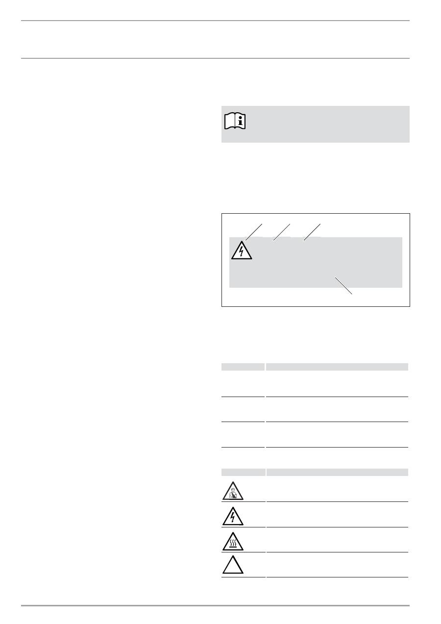
1.2.1 Aufbau
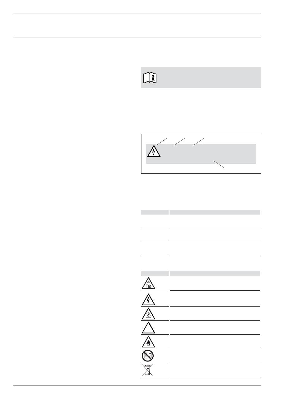
Sicherheitshinweis
Sicherheitshinweise bestehen aus einem Warnsymbol, einem
Signalwort und einem Hinweistext. Die Sicherheitshinweise sind
grau hinterlegt.
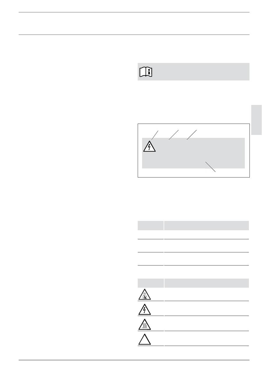
Beispiel:
GEFAHR Stromschlag
Bringen Sie das Gerät so an, dass Schalt- und
Regelvorrichtungen nicht von einer in der Bade-
wanne oder unter der Dusche befindlichen Person
berührt werden können.
1
2
3
4
1 Symbol (siehe Kapitel Warnsymbole/Symbole)
2 Signalwort (siehe Kapitel Signalworte)
3 Bennenung (siehe Kapitel Warnsymbole/Symbole)
4 Hinweistext
1.2.2 Signalworte
Z.&C<qHV`
¼®¼şŒşĉÖ
GEFAHR
Das Signalwort GEFAHR kennzeichnet Hinweise, deren
Nichtbeachtung schwere Verletzungen oder Tod zur Folge
haben.
WARNUNG
Das Signalwort WARNUNG kennzeichnet Hinweise, deren
Nichtbeachtung schwere Verletzungen oder Tod zur Folge
haben können.
VORSICHT
Das Signalwort VORSICHT kennzeichnet Hinweise, deren
Nichtbeachtung zu mittelschweren oder leichten Ver-
letzungen führen können.
1.2.3 Warnsymbole/Symbole
q|ļĉńźăĒù
¼ĉĉ¼ĉĉşĉÖ
Verletzung
Stromschlag
Verbrennung oder Verbrühung
!
andere Situationen
BEDIENUNG
1. Allgemeine
Hinweise
___________________________________________2
1.1 Dokumentinformation
_____________________________________________ 2
1.2 Zeichenerklärung
___________________________________________________ 2
2. Sicherheit
________________________________________________________3
2.1 Bestimmungsgemäße
Verwendung
____________________________ 3
2.2 Sicherheitshinweise
________________________________________________ 3
2.3 Prüfzeichen
__________________________________________________________ 4
3. Gerätebeschreibung ____________________________________________4
4. Bedienung
______________________________________________________4
4.1 Beschreibung der Bedienoberfläche ___________________________ 4
4.2 Frostschutz___________________________________________________________ 4
4.3 Begrenzung des Temperaturreglers ____________________________ 4
4.4 Außerbetriebnahme
_______________________________________________ 5
5. Reinigung,
Pflege
und Wartung _______________________________5
6.
Was tun wenn ... ________________________________________________5
INSTALLATION
7. Sicherheit
________________________________________________________6
7.1 Allgemeine
Sicherheitshinweise
________________________________ 6
7.2 Vorschriften, Normen und Bestimmungen ____________________ 6
8. Gerätebeschreibung ____________________________________________6
8.1 Lieferumfang
________________________________________________________ 6
9. Montage
_________________________________________________________6
9.1 Montage mit Wandhalterung ____________________________________ 6
9.2 Aufstellung
mit Standfuß _________________________________________ 7
9.3 Elektrischer
Anschluss
_____________________________________________ 7
10. Störungsbehebung
_____________________________________________7
11. Übergabe
des Gerätes _________________________________________7
12. Technische
Daten
_______________________________________________8
12.1 Abmaße Wandhängende Variante ______________________________ 8
12.2 Abmaße Mobile Standvariante __________________________________ 8
12.3 Datentabelle _________________________________________________________ 9
UMWELT UND RECYCLING
KUNENDIENST UND GARANTIE
.CeC&
Z.+V+.`
qqqĪZ`.<é<`VHCĪHB
CZ%
ŗ
e
`Z
+
Brand
Gerät nicht abdecken
Geräteentsorgung
1.2.4 Textzeichen und Formate in dieser Dokumentation
Lesen Sie Texte neben diesem Bildzeichen sorgfältig
durch.
»
Diese Passagen und das „
»
“ Symbol zeigen Ihnen, dass Sie
etwas tun müssen. Die erforderlichen Handlungen werden
Schritt für Schritt beschrieben.
— Passagen mit diesem „
–
“ Symbol zeigen Ihnen Aufzählungen.
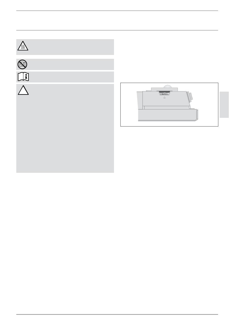
1.2.5 Hinweise am Gerät
Gerät nicht abdecken!
1.2.6 Maßeinheiten
Die Maße in diesem Dokument sind in mm angegeben.
Abweichende Maßeinheiten werden jeweils extra an-
gegebenen.
2. Sicherheit
2.1 Bestimmungsgemäße
Verwendung
Das Gerät dient zur Erwärmung von Wohn räumen.
Eine andere oder darüber hinausgehende Benutzung gilt als nicht
bestimmungsgemäß. Zum bestimmungsgemäßen Gebrauch ge-
hört auch das Beachten dieser Anleitung. Bei Änderungen oder
Umbauten am Gerät erlischt jegliche Gewährleistung!
2.2 Sicherheitshinweise
Betreiben Sie das Gerät nur komplett installiert und mit allen
Sicherheitseinrichtungen.
WARNUNG Brand
Betreiben Sie das Gerät nicht ...
—
wenn die Räume durch Chemikalien, Staub, Gase
oder Dämpfe feuer- oder explosionsgefährdet
sind.
—
in unmittelbarer Nähe von Leitungen oder Behält-
nissen, die brenn bare oder explosionsge fährdete
Stoffe führen oder enthalten.
—
wenn im Aufstellraum Arbeiten wie Verlegen,
Schleifen, Versiegeln, durchgeführt werden.
—
wenn mit Benzin Sprays, Bohnerwachs oder Ähn-
lichem umgegangen wird. Lüften Sie den Raum vor
dem Heizen ausreichend.
—
wenn die Mindestabstände zu angrenzenden
Objektflächen wie zum Beispiel Möbel, Gardinen,
Vorhänge und Textilien oder sonstige brennbaren
Materialien unterschritten werden (Mindest-
abstände siehe Kapitel Technische Daten).
—
wenn ein Gerätebauteil beschädigt ist, das Gerät
heruntergefallen ist oder bereits eine Fehlfunktion
vorlag.
WARNUNG Verletzung
Sollten Kinder oder Personen mit eingeschränkten
körperlichen, sensorischen oder geistigen Fähigkeiten
das Gerät bedienen, stellen Sie sicher, dass dies nur
unter Aufsicht oder nach entsprechender Einweisung
durch eine für ihre Sicherheit zuständige Person ge-
schieht.
Beaufsichtigen Sie Kinder, um sicherzustellen, dass sie
nicht mit dem Gerät spielen!
WARNUNG Brand
Auf dem Gerät oder in dessen unmittelbarer Nähe
dürfen keine brennbaren, entzündbaren oder wärme-
dämmenden Gegenstände oder Stoffe, wie Wäsche,
Decken, Zeitschriften, Behälter mit Bohnerwachs oder
Benzin, Spraydosen und dergleichen gelegt werden.
WARNUNG Verbrennung
Die Gehäuseoberflächen des Gerätes und die aus-
tretende Luft werden bei Betrieb heiß (über 80 °C).
.CeC&
&V`Z+V.eC&
Ô
CZ%
qqqĪZ`.<é<`VHCĪHB
VORSICHT Überhitzung
Gerät nicht abdecken.
Treten Sie nicht auf das Gerät.
!
Achten Sie bei der Verwendung des mobilen Stand-
gerätes auf folgendes:
—
Decken Sie die Anschlussleitung nicht mit einem
Teppich oder Läufer ab. Legen Sie die Anschluss-
leitung außerhalb des Verkehrsweges, um zu ver-
hindern dass jemand über die Leitung stürzt oder
das Gerät umgeschmissen wird.
—
Vermeiden Sie den Einsatz eines Verlängerungs-
kabels. Falls notwendig, verwenden Sie nur
ein unbeschädigtes Verlängerungskabel mit
ausreichendem Kabelquerschnitt für die volle
Geräteleistung sowie unbeschädigte Stecker be-
ziehungsweise Kupplungen und ausreichender
Schutzmaßnahme.
—
Stellen Sie das Gerät auf eine feste Unterlage. Bei
weichen Unterlagen kann das Gerät umkippen,
oder die Luftöffnungen könnten blockiert werden.
—
Verschieben oder Tragen Sie das Gerät auf keinen
Fall durch Ziehen am Netzanschlusskabel.
—
Wenn Sie das Gerät als Standgerät benutzten,
stellen Sie es nicht in Badezimmer oder ähnlich
feuchten Räumen sowie im freien auf.
CE-Kennzeichnung
Die CE-Kennzeichnung belegt, dass das Gerät alle grundlegenden
Anforderungen erfüllt:
— Richtlinie über die elektromagnetische Verträglichkeit
— Niederspannungsrichtlinie
2.3 Prüfzeichen
Siehe Typenschild.
Das Typenschild befindet sich rechts außen am Gerät.
3. Gerätebeschreibung
Das Gerät ist ein Elektro-Direktheizgerät und kann als wand-
hängendes Gerät oder alternativ als mobiles Standgerät mit
montierten Standfüßen eingesetzt werden.
Das Gerät eignet sich zum Beispiel als Vollheizung oder als Über-
gangs- und Ergänzungsheizung für kleinere Räume wie zum Bei-
spiel Hobbyraum und Gästezimmer.
Die Luft im Gerät wird durch einen Heizkörper erwärmt und tritt
über die natürliche Konvektion oben durch das Luftaustrittgitter
aus. Durch die in der Geräteunterseite vorhandenen Öffnungen
strömt kühle Raumluft nach.
Nach der Wandbefestigung beziehungsweise Montage der Füße
und elektrischem Anschluss mittels Netzstecker ist das Gerät be-
triebsbereit.
4. Bedienung
4.1
Beschreibung der Bedienoberfläche
»
Schalten Sie das Gerät über den Schalter auf der rechten Seite
des Gerätes ein.
»
Stellen Sie über den Temperatur-Wählknopf die gewünschte
Raumtemperatur stufenlos ein (Temperaturwerte siehe Kapitel
Technische Daten).
26
_0
7
_3
1
_0
037
Sobald die eingestellte Raumtemperatur erreicht ist, wird diese
durch zeitweises Heizen konstant auf der eingestellten Temperatur
gehalten (die Heizleistung des Gerätes muss hierbei mindestens
dem benötigten Wärmebedarf des Raumes entsprechen).
Sind mehrere Geräte in einem Raum vorhanden, kann die Ein-
stellung am Temperatur-Wählknopf an jedem Gerät unterschied-
lich sein.
Um bei geöffneten Fenstern einen zu hohen Stromverbrauch zu
vermeiden, sollten Sie das Gerät während des Lüftens ausschalten.
4.2 Frostschutz
»
Stellen Sie den Temperatur-Wählknopf auf Rechtsanschlag. In
dieser Stellung schaltet der Temperaturregler die Heizung auto-
matisch ein, falls die Raumtemperatur unter die Frostschutz-
temperatur absinkt.
.CeC&
V.C.&eC&©T%<&eCqV`eC&
qqqĪZ`.<é<`VHCĪHB
CZ%
Ñ
e
`Z
+
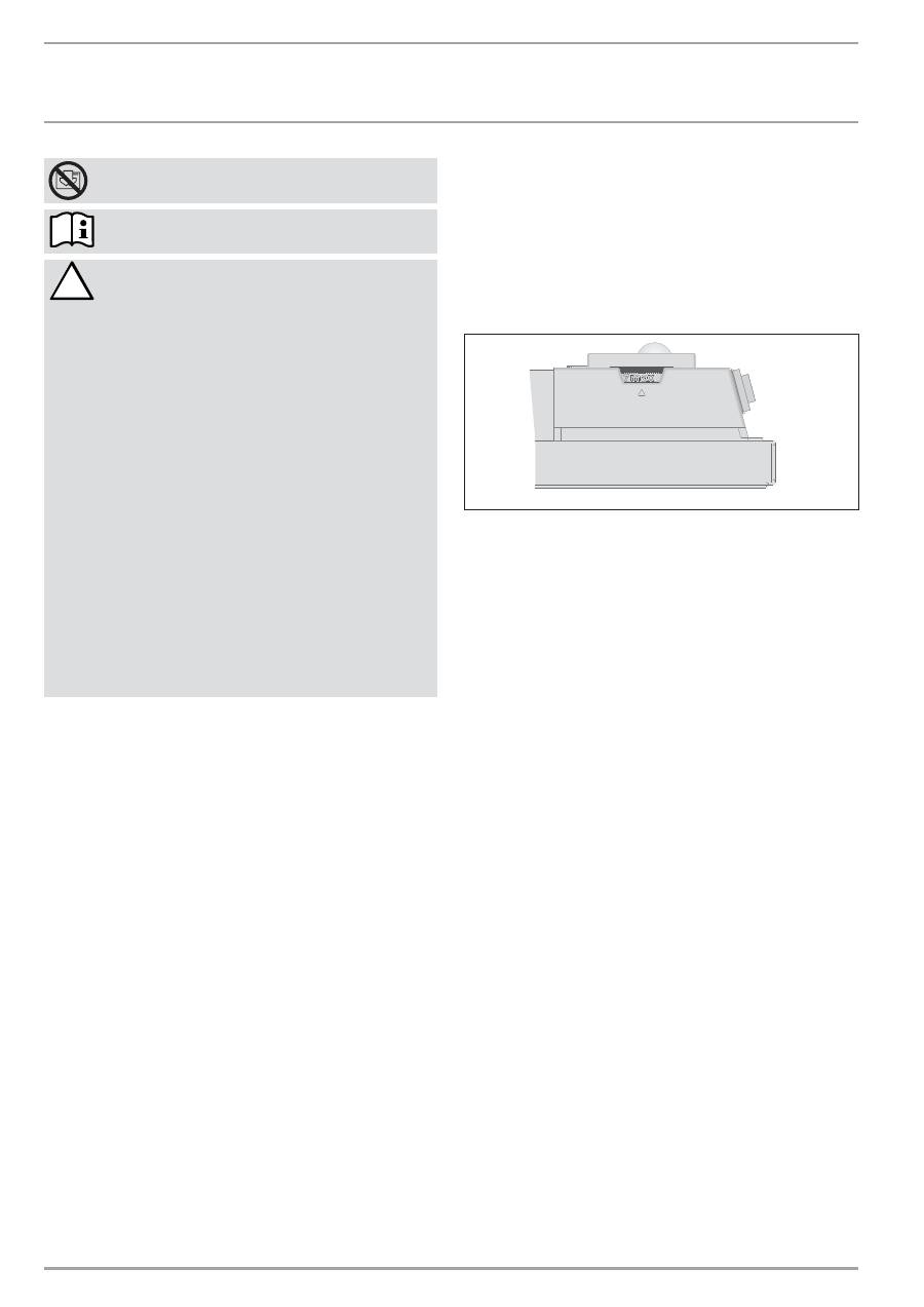
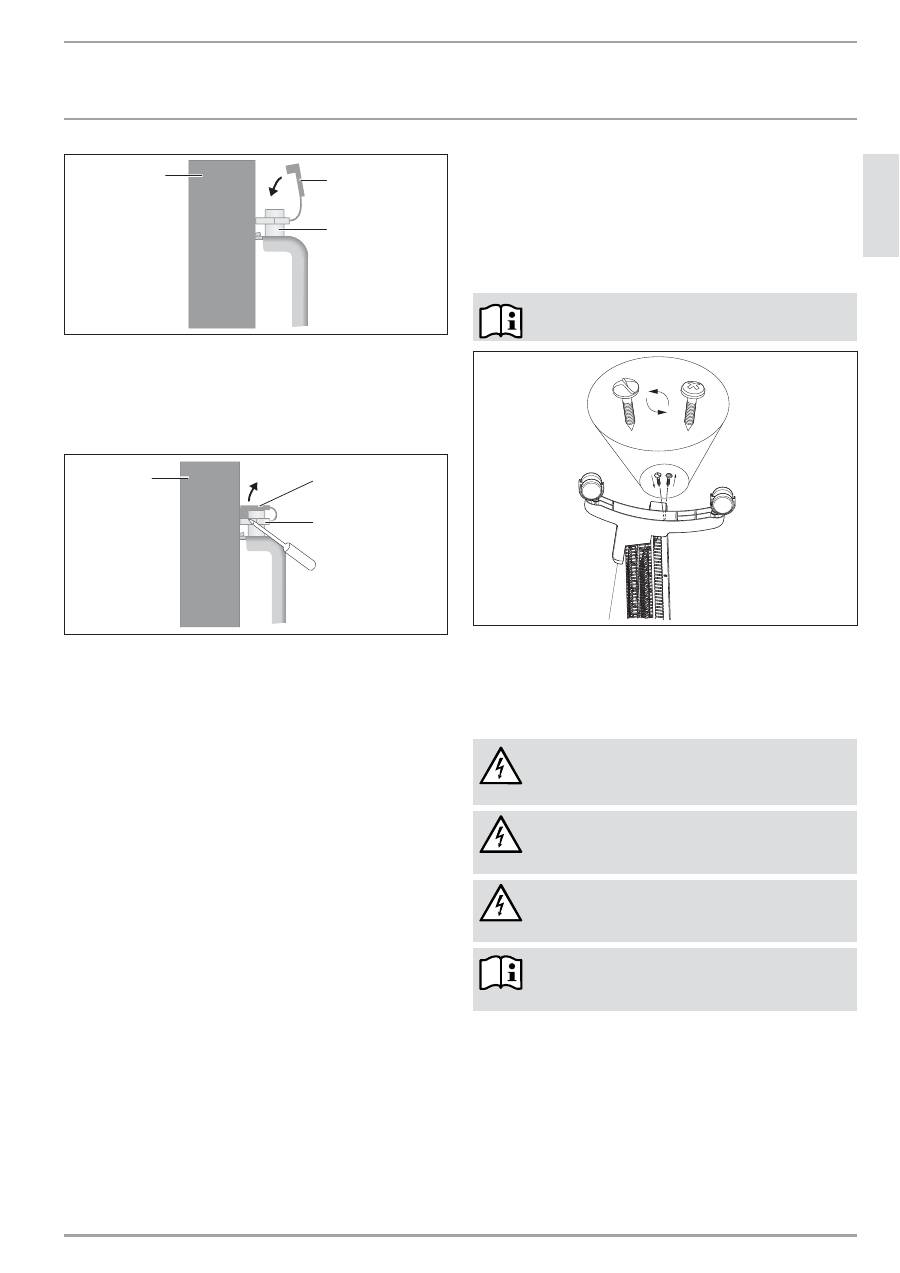
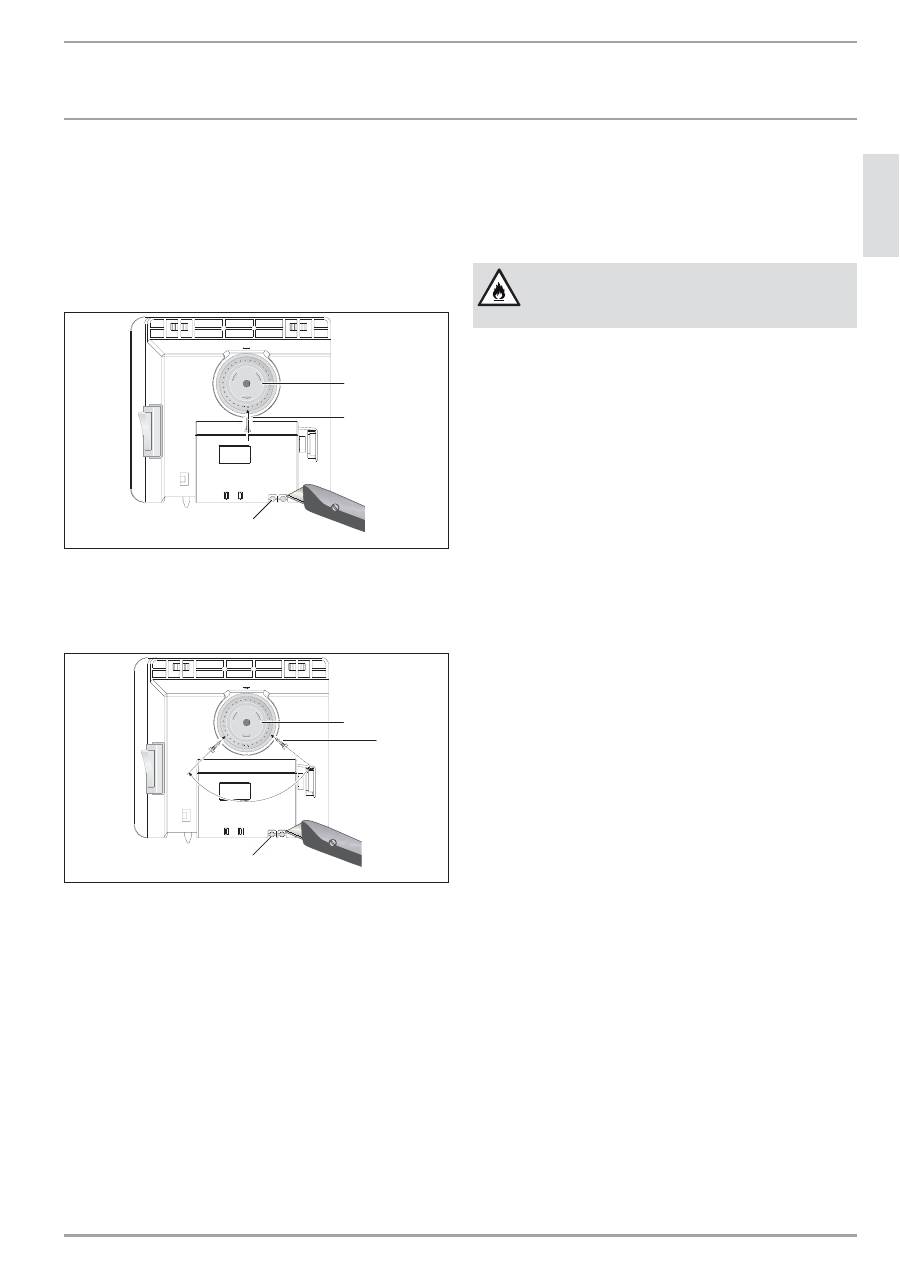
4.3
Begrenzung des Temperaturreglers
Mit den beiden an der Rückseite des Schaltgehäuses angebrachten
Stiften können Sie den Temperaturregler auf eine bestimmte Ein-
stellung fixieren oder den Temperatur-Einstellbereich begrenzen.
»
Brechen Sie die Stifte heraus.
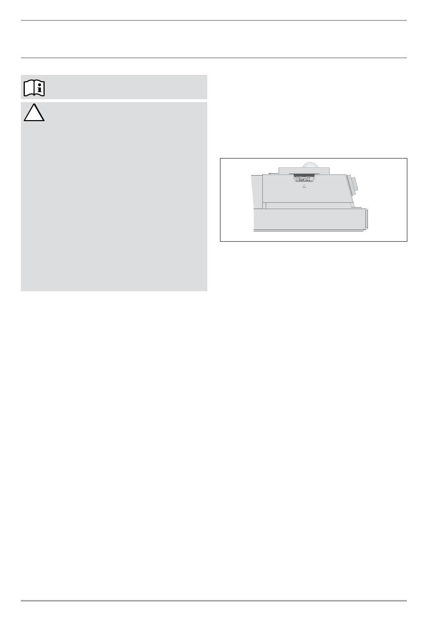
»
Um die eingestellte Temperatur zu fixieren, stecken Sie einen
Stift in das gegenüberliegende Loch (siehe Bild).
1
1
1
2
26
_0
7
_3
1
_0
03
8
1 Stift
2 Temperatur-Wähler
»
Um den Temperatur-Einstellbereich zu begrenzen, stellen Sie
jeweils den Minimalwert und Maximalwert am Temperatur-
Wählknopf ein, und stecken jeweils den Stift in ein etwas ver-
setzt gegenüberliegendes Loch (siehe Bild).
2
6
_0
7
_3
1
_0
1
7
1
1
1
1
2
1 Stift
2 Temperatur-Wähler
4.4 Außerbetriebnahme
»
Schalten Sie den Schalter rechts am Gerät auf AUS.
5. Reinigung, Pflege und Wartung
Sollten am Gerätegehäuse leichte bräunliche Verfärbungen auf-
treten, reiben Sie diese möglichst sofort mit einem feuchten Tuch
ab. Reinigen Sie das Gerät in kaltem Zustand mit gebräuchlichen
Pflegemitteln. Vermeiden Sie scheuernde und ätzende Pflege-
mittel.
VORSICHT Brand
Sprühen Sie kein Reinigungsspray in die Luftschlitze.
Achten Sie darauf das keine Feuchtigkeit in das Gerät
eindringt.
Bei den regelmäßigen Wartungen empfehlen wir, auch die
Kontroll- und Regelorgane überprüfen zu lassen. Spätestens 10
Jahre nach Erstinbetriebnahme sollten Sicherheits-, Kontroll- und
Regelorgane durch den Fachhandwerker überprüft werden.
6. Was tun wenn ...
... das Gerät nicht heizt:
Überprüfen Sie die eingestellte Temperatur am Gerät und die
Sicherung in der Hausinstallation.
Das Gerät besitzt einen Schutztemperaturregler, der bei Über-
hitzung das Gerät abschaltet. Nach Beseitigung der Ursache (zum
Beispiel verdeckte Luftaus- oder -eintrittsöffnung) geht das Gerät
nach einer Abkühlzeit von wenigen Minuten wieder in Betrieb.
Können Sie den Fehler nicht beheben, rufen Sie den Fachhand-
werker. Zur besseren und schnelleren Hilfe teilen Sie ihm die
Nummer (Nr. XXXXXX - XXXX - XXXXXX) vom Typenschild mit:
ō
CZ%
qqqĪZ`.<é<`VHCĪHB
.CZ`<<`.HC
Z.+V+.`
7. Sicherheit
Die Wartung und Reparatur des Gerätes darf nur von einem Fach-
handwerker durchgeführt werden.
7.1 Allgemeine
Sicherheitshinweise
Wir gewährleisten eine einwandfreie Funktion und Betriebssicher-
heit nur, wenn das für das Gerät bestimmte Original-Zubehör und
die originalen Ersatzteile verwendet werden.
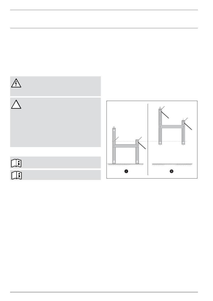
GEFAHR Stromschlag
Bringen Sie das Gerät bei der Wandmontage so an,
dass Schalt- und Regelvorrichtungen nicht von einer
in der Badewanne oder unter der Dusche befindlichen
Person berührt werden können.
!
VORSICHT
—
Bringen Sie das Wandgerät nur an einer senk-
rechten, bis mindestens 85 °C temperatur-
beständigen Wand an.
—
Halten Sie die Mindestabstände zu angrenzenden
Objektflächen ein (Mindestabstände siehe Kapitel
Technische Daten).
—
Bringen Sie das Gerät nicht unmittelbar unter
einer Wandsteckdose an.
—
Achten Sie darauf, dass das Anschlusskabel keine
Geräteteile berührt.
7.2
Vorschriften, Normen und Bestimmungen
Beachten Sie alle nationalen und regionalen Vor-
schriften und Bestimmungen zur Installation, Montage
und Inbetriebnahme.
8. Gerätebeschreibung
8.1 Lieferumfang
— Wandhalterung (am Gerät eingehängt)
— Standfüße
— Sicherheitsschrauben
9. Montage
9.1 Montage
mit
Wandhalterung
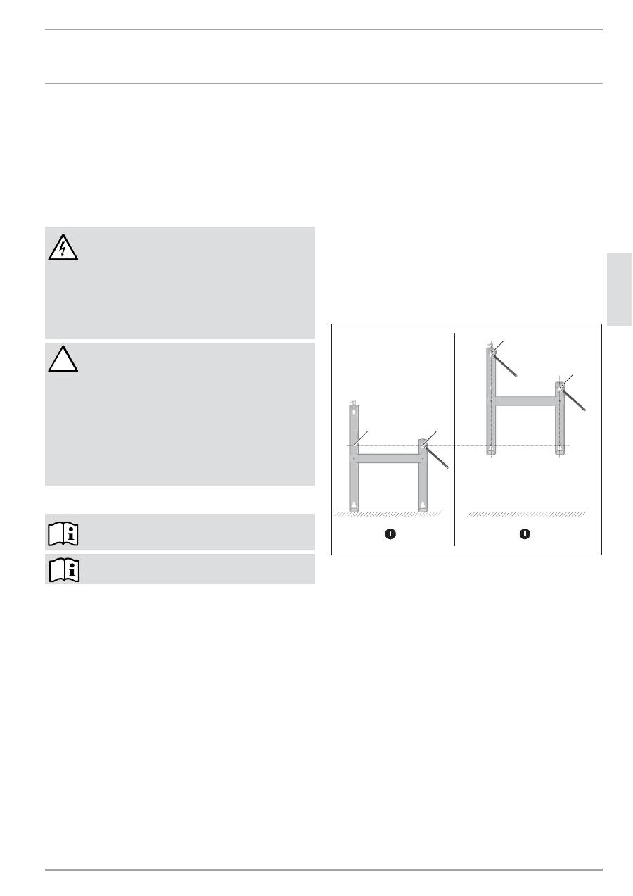
9.1.1 Montage
der
Wandhalterung
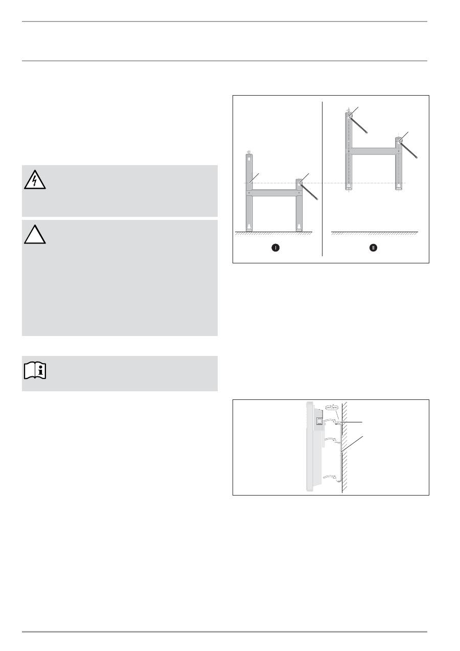
Sie können die Wandhalterung auch als Schablone zur Wand-
befestigung verwenden, dies gewährleistet den notwendigen
Bodenabstand.
»
Hängen Sie die Wandhalterung aus.
»
Stellen Sie die mittelpunktorientierte Wandhalterung waagerecht
auf den Boden und kennzeichnen Sie die Bohrungen Punkt
1 und 2.
»
Heben Sie die Wandhalterung hoch, so dass die unteren
Bohrungen in der Wandhalterung deckungsgleich mit den
gerade angebrachten Kennzeichnungen an der Montagewand
sind.
»
Kennzeichnen Sie die Bohrungen 3 und 4 an der Montagewand.
DDD
2
6
_0
7
_3
1
_0
1
2
4
1
3
2
4
»
Bohren Sie an allen 4 Kennzeichnungen Löcher. Befestigen Sie
die Wandhalterung mit geeigneten Materialien (Schrauben,
Dübel) je nach Wandart. Mit den vertikalen Langlöchern können
Sie ein Verlaufen der Befestigungsbohrung ausgleichen.
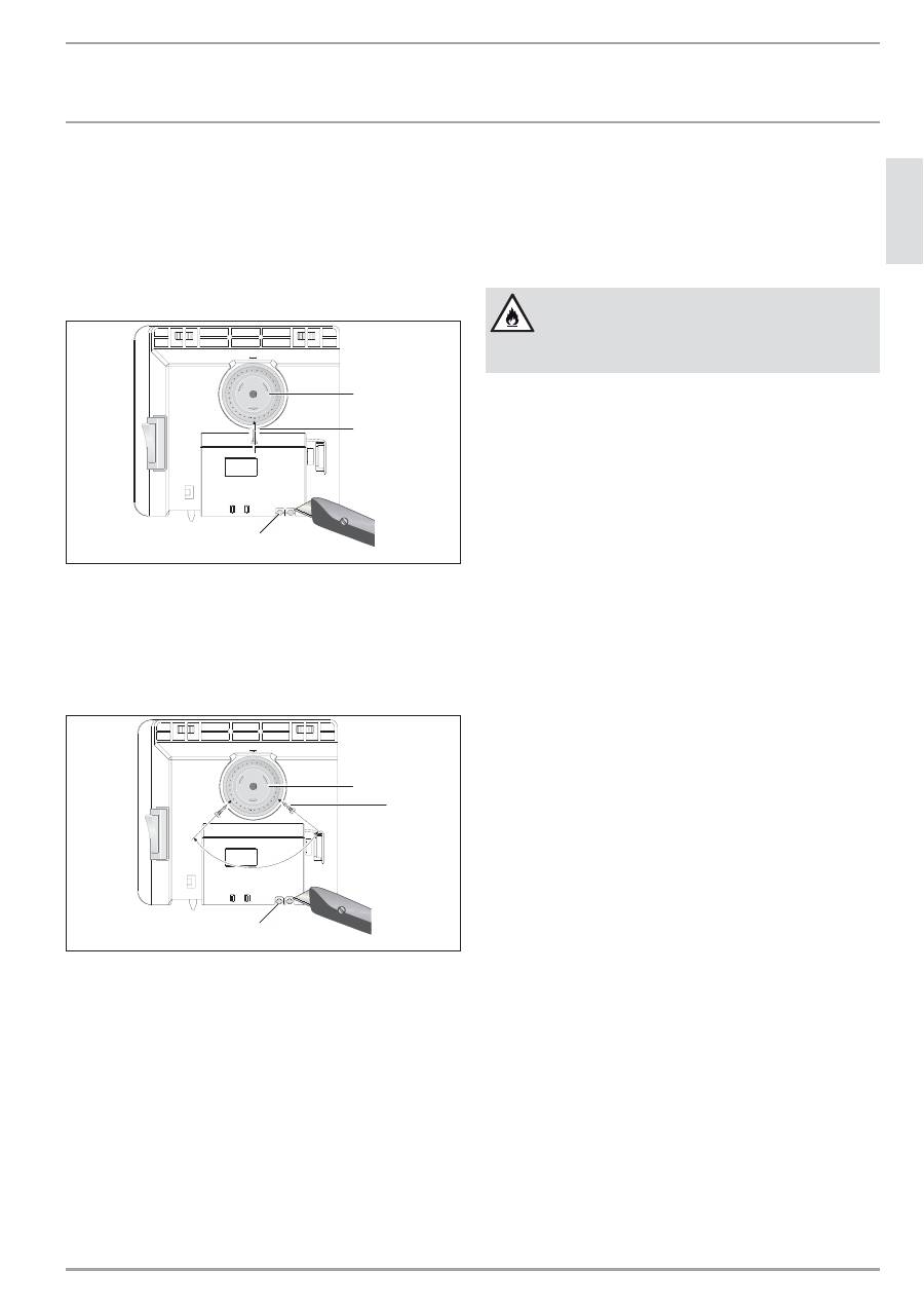
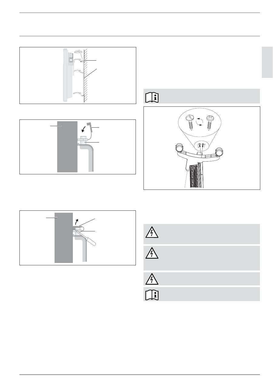
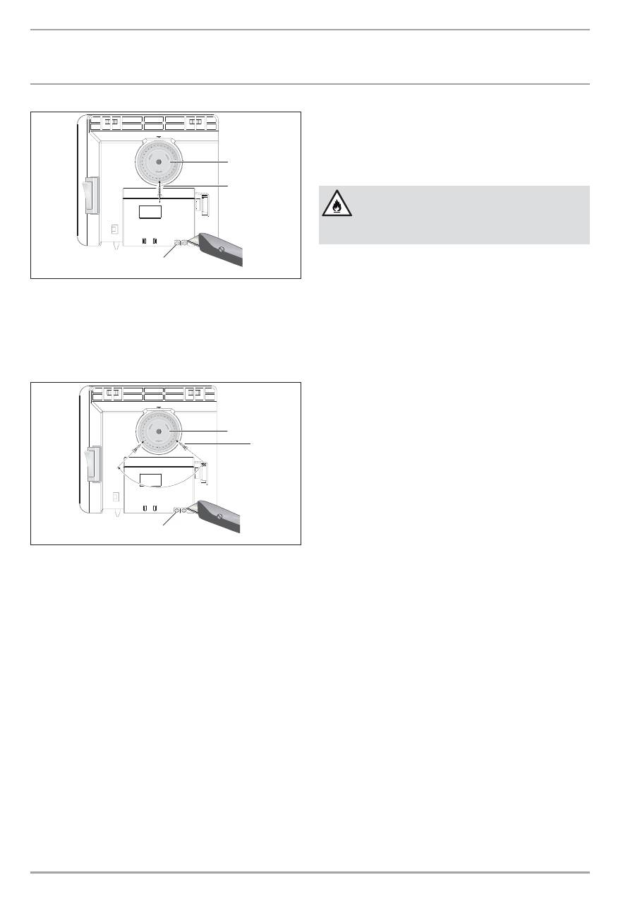
9.1.2 Montage des Gerätes
»
Hängen Sie das Gerät mit den Aufnahmeschlitzen in der Geräte-
rückseite gleichzeitig auf die vier Laschen der Wandhalterung.
»
Drücken Sie das Gerät zur Arretierung an.
»
Drehen Sie den Verschlussbolzen der Wandhalterung im Uhr-
zeigersinn bis zum Anschlag, damit ist die Befestigung verriegelt.
»
Drücken Sie die Sicherungskappe auf den Verschlussbolzen,
damit dieser sich nicht mehr zurückdrehen lässt.
2
6
_0
7
_3
1
_0
0
3
5
1
2
1 Verschlussbolzen
2 Wandhalterung
qqqĪZ`.<é<`VHCĪHB
CZ%
Ō
e
`Z
+
.CZ`<<`.HC
Z`MVeC&Z+eC&
26
_0
7
_3
1
_0
1
2
7
1
2
3
1 Gerät
2 Sicherungskappe
3 Verschlussbolzen
9.1.3 Demontage des Gerätes
»
Lösen Sie die Sicherungskappe vom Verschlussbolzen.
2
6
_0
7
_3
1
_0
1
2
8
1
2
3
1 Gerät
2 Sicherungskappe
3 Verschlussbolzen
»
Lösen Sie den Verschlussbolzen der Wandhalterung entgegen
dem Uhrzeigersinn.
»
Heben Sie das Gerät leicht an und nehmen Sie es nach vorn von
der Wandhalterung ab.
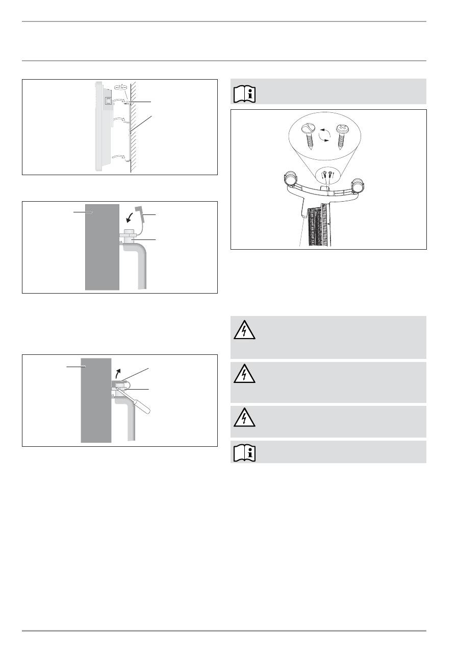
9.2 Aufstellung
mit
Standfuß
»
Hängen Sie die Wandhalterung aus.
»
Entfernen Sie links und rechts unten am Gerät nur die beiden
äußeren Schrauben.
»
Setzen Sie die Standfüße unten am Gerät jeweils so an, dass sich
diese hinten am Gerät in die Aussparung einfügen.
Schrauben Sie die Füße mit den beiliegenden Sicher-
heitsschrauben fest an.
2
6
_0
7
_3
1
_0
1
2
5
9.3 Elektrischer
Anschluss
»
Achten Sie auf ausreichenden Zuleitungsquerschnitt bauseits.
»
Achten Sie darauf, dass im Abstand von mindestens 10 cm seit-
lich vom Gerät eine Steckdose installiert ist.
GEFAHR Stromschlag!
Führen Sie alle elektrischen Anschluss- und
Installationsarbeiten nach Vorschrift aus.
GEFAHR Stromschlag!
Das Gerät muss über eine Trenn strecke von mindestens
3 mm allpolig vom Netz getrennt werden können.
GEFAHR Stromschlag!
Die Installation mit festverlegter Anschlussleitung ist
nicht zulässig.
Beachten Sie das Typenschild. Die angegebene
Spannung muss mit der Netzspannung überein-
stimmen.
10. Störungsbehebung
Die Netzanschlussleitung darf bei einem Austausch nur von einem
Fachhandwerker mit Original Ersatzteilen von uns ersetzt werden.
11. Übergabe des Gerätes
Erklären Sie dem Benutzer die Funktionen des Gerätes. Machen
Sie ihn besonders auf die Sicherheitshinweise aufmerksam. Über-
reichen Sie dem Benutzer die Bedienungs- und Installations-
anleitung.
Ä
CZ%
qqqĪZ`.<é<`VHCĪHB
.CZ`<<`.HC
`+C.Z+`C
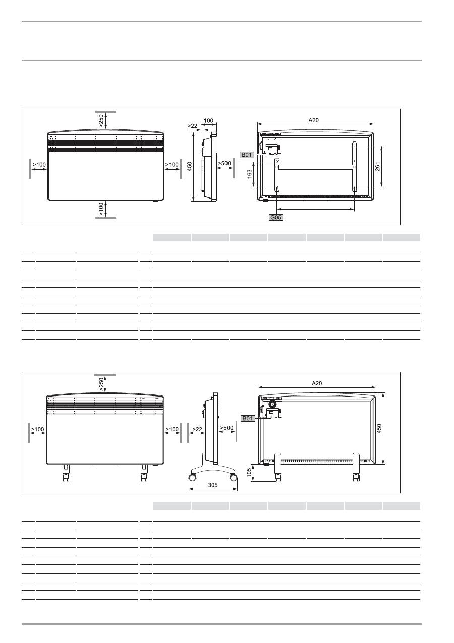
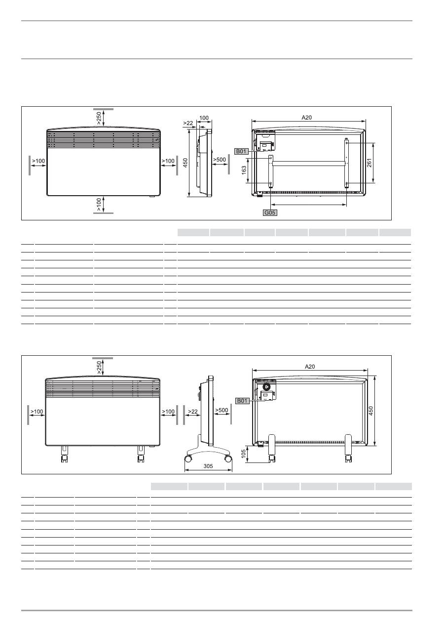
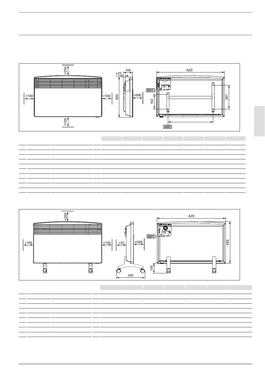
12. Technische Daten
12.1 Abmaße Wandhängende Variante
8
0
_0
7
_3
1
_000
9
CZŌÑ%
CZĜƃƃ%
CZĜŝÑ%
CZĜÑƃ%
CZĜŌÑ%
CZŝƃƃ%
CZŝÑƃ%
A10 Gerät
Höhe
mm
450
A20 Gerät
Breite
mm
445
445
590
590
740
740
890
A30 Gerät
Tiefe
mm
100
A50 Gerät
Mindestabstand oben
mm
250
A51
Gerät
Mindestabstand unten
mm
100
A52 Gerät
Mindestabstand rechts
mm
100
A53 Gerät
Mindestabstand links
mm
100
A54 Gerät
Mindestabstand vorne
mm
500
A55 Gerät
Mindestabstand hinten
mm
22
B01 Durchführung für elektr. Leitungen
G05 Wandhalterung Lochabstand
mm 195
195
343
343
491
491
639
12.2 Abmaße Mobile Standvariante
8
0
_0
7
_3
1
_000
9
CZŌÑ%
CZĜƃƃ%
CZĜŝÑ%
CZĜÑƃ%
CZĜŌÑ%
CZŝƃƃ%
CZŝÑƃ%
A10 Gerät
Höhe
mm
450
A13 Gerät
Höhe Stellfüße
mm
105
A20 Gerät
Breite
mm
445
445
590
590
740
740
890
A30 Gerät
Tiefe
mm
305
A50 Gerät
Mindestabstand oben
mm
250
A52 Gerät
Mindestabstand rechts
mm
100
A53 Gerät
Mindestabstand links
mm
100
A54 Gerät
Mindestabstand vorne
mm
500
A55 Gerät
Mindestabstand hinten
mm
22
B01 Durchführung für elektr. Leitungen

qqqĪZ`.<é<`VHCĪHB
CZ%
Ď
e
`Z
+
.CZ`<<`.HC
`+C.Z+`C
12.3 Datentabelle
BĒ®¼ùù
Typ
CNS 75 F
CNS 100 F
CNS 125 F
CNS 150 F
CNS 175 F
CNS 200 F
CNS 250 F
Bestellnummer
229789
229790
229791
229792
229793
229794
229795
Leistung
kW
0,75
1,0
1,25
1,5
1,75
2,0
2,5
Elektroanschluss
1/N ~ 230 V
1/N ~ 230 V
1/N ~ 230 V
1/N ~ 230 V
1/N ~ 230 V
1/N ~ 230 V
1/N ~ 230 V
Temperatur-
Einstellbereich
~ °C
6 ... 30
6 ... 30
6 ... 30
6 ... 30
6 ... 30
6 ... 30
6 ... 30
Frostschutz
~ °C
6
6
6
6
6
6
6
Schutzklasse
II
II
II
II
II
II
II
Schutzart IP 24,
spritzwassergeschützt
x
x
x
x
x
x
x
Gewicht
kg
4,6
4,6
6,0
6,0
7,2
7,2
8,4

Ĝƃ
CZ%
qqqĪZ`.<é<`VHCĪHB
&VBCt
:eCC.CZ`eC&VC`.
&:77>00498,70490&>G<?92,904908?9=0<0<$<:/?6>0,?1><0>09
=>0309A4<39099,>H<74.384>%,>?9/',>C?<&04>0
%?109&40?9=,9
I 849-049<?109,?=/08/0?>=.3090=>
90>C",B48,7I 849-049<?109,?=":-471?9690>C09
:/0<=.3<04-09&40?9=
&>40-077><:98-:
?9/09/409=>
H<=>09-0<20<&><,D0:7C849/09
",476?9/09/409=>=>40-0707><:9/0
,BI 849,?=/08/0?>=.3090=>90>C
",B48,7I 849-049<?109,?=":-471?9690>C09
*04>0<09=.3<41>09=49/,?1/0<70>C>09&04>0,?1201H3<>
(9=0<09 ?9/09/409=>0<<04.309&40>0701:94=.3<?9/?8/40(3<
,?.3,9&,8=>,209?9/&:99>,209=:A40,9040<>,209 ?9/09
/409=>049=F>C00<1:7209AF3<09/?9=0<0<0=.3F1>=C04>09@:9
-4=(3<1<04>,2=-4=(3<7=&:9/0<=0<@4.0-40>09
A4< ?9/09/409=>049=F>C0-4=(3<H</40=09&:9/0<=0<@4.0
=:A40 ?9/09/409=>049=F>C0,9&,8=&:99?9/040<>,209
A0</093G30<0$<04=0-0<0.390>
40=0,<,9>40-0/492?9209<02079C?=F>C74.30,<,9>40704=>?9209
@:9?9=20209H-0</089/6?9/09&40><0>0990-09/4020=0>C
74.3090AF3<704=>?92=,9=;<H.30/0= ?9/094020=0>C74.309
0AF3<704=>?92=,9=;<H.3020209H-0</09=:9=>4209)0<><,2=
;,<>90<9=49/94.3>-0<H3<>
40=0,<,9>40-0/492?9209207>099?<1H<=:7.300<F>0/40@:8
9/6?9/0949/0<?9/0=<0;?-7460?>=.37,9/,7=#0?20<F>0
0<A:<-09A0</0949,<,9>40@0<><,26:88>94.3>C?=>,9/0
=:A04>/0<9/6?9/004920-<,?.3>0=0<F>:/0<04990?0=0<F>
=0490<=04>=@:904908,9/0<099/6?9/090<A4<->
40,<,9>40704=>?92A4</0<-<,.3>A099,9?9=0<090<F>09049
0<=>077?92=?9/ :/0<",>0<4,710370<4990<3,7-/0<,<,9>40
/,?0<,?1><4>>40,<,9>40?81,==>50/:.360490!04=>?92091H<
=:7.300<F>0,9/09090370<&.3F/09:/0<"F9207,?12<?9/
@:9)0<6,76?92.3084=.30<:/0<0706><:.3084=.30<49A4<6?92
10370<3,1>0<?1=>077?92-CA9=>,77,>4:9=:A40?9=,.3208FD0<
49<02?740<?920/409?92:/0<?9=,.3208FD0<9,9=;<?.3
9,380-CA)0<A09/?92,?1><0>09-09=:,?=20=.37:==09=49/
!04=>?9209,?12<?9/8,92073,1>0<:/0<?9>0<7,==090<*,<>?92
*4>>0<?92=049H==09:/0<=:9=>4209#,>?<0<=.3049?9209
40,<,9>400<74=.3>A099,80<F>%0;,<,>?<09492<4110:/0<
-F9/0<?9209/?<.394.3>@:9?9=,?>:<4=40<>0$0<=:909@:<
209:8809A?</09
40,<,9>40704=>?92?81,==>/40=:<21F7>420$<H1?92/0=0<F>0=
A:-04C?9F.3=>0<84>>07>A4</:-049,<,9>40,9=;<?.3-0=>03>
8,<,9>401,7709>=.304/09,77049A4<,?1A07.30<>/0<0370<
-03:-09A4</==>03>?9=1<040490%0;,<,>?</0=0<F>0=,?=
1H3<09C?7,==09:/0<=07-=>,?=C?1H3<09>A,420,?=20A0.3=07>0
'0470A0</09?9=0<4209>?8
H</40,?0<?9/%04.3A04>0/0<,<,9>40H-0<903809A4<=F8>
74.30",>0<4,7?9/":9>,206:=>09
&:A04>/0< ?9/0A0209/0=,<,9>401,770=,?12<?9/20=0>C
74.30<0AF3<704=>?92=,9=;<H.3020209,9/0<0)0<><,2=;,<>90<
!04=>?92090<3,7>093,>09>1F77>0490!04=>?92=;4.3>@:9?9=
&:A04> 0490 ,<,9>40704=>?92 0<-<,.3> A4</ H-0<903809 A4<
60490,1>?921H</400=.3F/42?920490=0<F>0=/?<.340-
=>,370?0<?1<?3<:/0<F3974.30(<=,.309
E-0</40@:<=>0309/C?20=,2>09,<,9>40704=>?9209349,?=20309/
6,99/0<9/6?9/09,.3/40=0<,<,9>40604909=;<H.30A0209
84>>07-,<0<&.3F/09:/0<:720=.3F/09/40/?<.3/,=0<F>@0<
?<=,.3>A0</0949=-0=:9/0<0,?1<=,>C,?D0<3,7-/0=0<F>0=
09>=>,9/090<&.3F/09207>09/8,.3090=0>C74.309=;<H.30
/0= ?9/09?9=20209H-0<:/0<20209H-0<<4>>09-704-09?9
-0<H3<>
H<48;<4@,>09,?=3,7>04920=0>C>00<F>0-0><F2>/40,<,9>40
/,?0<":9,>048H-<4209C?804=;407-040490849=,>C/0<
0<F>0490A0<-0,9/A0<6=:/0<9/?=><40-0><40-09-0><F2>
/40,<,9>40/,?0<":9,>0
40,<,9>40/,?0<-02499>1H<50/0=0<F>84>/0<E-0<2,-0/0=
0<F>0=,9/09 ?9/09/0</,=0<F>C?80<=>09",7049=0>C>
,<,9>40704=>?92091H3<0994.3>C?0490<)0<7F920<?92/0<,<,9
>40/,?0<?<.3/400<-<,.3>0,<,9>40704=>?92A4</6049090?0
,<,9>40/,?0<49,9220=0>C>40=247>1H<,7700<-<,.3>09,
<,9>40704=>?920949=-0=:9/0<01H<0>A,4204920-,?>0<=,>C>0470
:/0<1H</40<=,>C74010<?920490=90?090<F>0=
,<,9>40,9=;<H.30=49/@:<-7,?1/0<,<,9>40/,?0<4990<3,7-
@:9CA04*:.3099,.3/08/0<",92070<6,99>A?</0-04?9=
,9C?807/09,-048H==0992,-09C?80370<C?80<F>?9/
C?8+04>;?96>/0<0=>=>077?92208,.3>A0</097=,<,9>40
9,.3A04=4=>/40%0.39?92:/0<049=:9=>420</,>40<>0< ,?19,.3
A04=-04C?1H20903709/40@:<209,99>0992,-09:/0<(9>0<
7,209-0=>03>6049,<,9>40,9=;<?.3
!
*4< =49/ 94.3> @0<;4.3>0> ,<,9>40704=>?9209 ,?D0<3,7- /0<
?9/0=<0;?-7460?>=.37,9/C?0<-<4920904&>G<?92090490=
48?=7,9/04920=0>C>090<F>0=4=>/40=0=2020-09091,77=,?1
01,3<?9/ :=>09/0= ?9/09,9/09 ?9/09/409=>490?>=.3
7,9/C?=09/0940%H.6=09/?920<1:72>0-091,77=,?101,3<?9/
:=>09/0= ?9/09>A,42020=0>C74.309=;<H.30/0= ?9/09
?9=20209H-0<:/0<20209H-0<<4>>09-704-09,?.349/40=08
,77?9-0<H3<>
H<,?D0<3,7-0?>=.37,9/=0<A:<-0900<F>0247>/40=0,<,9>40
94.3>=207>09/4050A047420920=0>C74.309):<=.3<41>09?9/20
20-09091,77=/40!4010<-0/492?9209/0<!F9/0<20=077=.3,1>-CA
/0=8;:<>0?<=
qqqĪZ`.<é<`VHCĪHB
CZ%
ĜĜ
e
`Z
+
&VBCt
eBq<`eCVt<.C&
+(2'0$0:23,!$1"':#(&2!$(',$, ,)-++2' !$,5(0$1
1-0&%:*2(&4$0. ")2(22$'$*%$,($#($+5$*2731"'<27$,3,#
<!$0* 11$,($#($$0. ")3,&#$+ "'' ,#5$0)!75 "'' ,
#$*(0!$2$(*(&$,3,1&$+$(,1 ++(2#$+0-8' ,#$*3,##$+
"'' ,#5$0) "'' ,#$*(,$321"'* ,# ,$(,$+5(0)1 +$,
<"), '+$3,#,21-0&3,&1)-,7$.2%<0#($3+5$*21"'-,$,#$
3% 0!$(23,&#$0$0. ")3,&$,
+ '+$,#$1*$)20-3,#*$)20-,()&$0:2$&$1$27$1*$)20-
(12#($)-12$,*-1$<")& !$#($1$1$0:2$1!$('0$0)-++3, *$,
++$*12$**$&$5:'0*$(12$2
(0$012$**$01-0&$,(+ '+$,#$00-#3)24$0 ,25-023,&%<0
$(,$3+5$*2&$0$"'2$$' ,#*3,&3,#$05$023,&#$0*2&$0:2$
$(2$0$,%-0+ 2(-,$,$0' *2$,($<!$0'0$-++3,$-#$0'0$,
"'' ,#5$0)$0 "'':,#*$0
9!$0# 1<"), '+$1612$+5$0#$,'-'$$"6"*(,&/3-2$,#$0
2$0( *($,$00$("'23+$.-,($,3,##($+5$*273$,2* 1
2$, +(2*$(12$,5(0&$+$(,1 +$(,$,5("'2(&$,$(20 &73+
+5$*21"'327
$0$(21!$(#$0,25(")*3,&,$3$0$0:2$ "'2$,5(0 3%$(,$'-'$
$"6"*(,&%:'(&)$(2#$0 2$0( *($,($-0 311$273,&%<0$(,$
2$0( *($#$04$05$023,&1(,##($$"6"*(,&6+!-*$3,##($
4-,3,14-0&$,-++$,$$,,7$("',3,&, "'
3,# # +(2#($4$01"'($#$,$,3,1212-%%$&$
20$,,2&$1 ++$*25$0#$,);,,$,
,21-0&$,($#($1$1$0:2% "'3,#1 "'&$0$"'2, "'#$,;02*("'
&$*2$,#$,-01"'0(%2$,3,#$1$27$,
Ĝŝ
CZ%
qqqĪZ`.<é<`VHCĪHB
HC`C`ZHTV`.HC
&CV<.C%HVB`.HC
1. General
information
1.1 Document
information
Read these instructions carefully before using the
appliance and retain them for future reference. Pass
on the instructions to any new users.
1.2
Key to symbols
1.2.1 Layout of safety information
Safety information comprises a warning symbol, a keyword and
a text giving information. Safety information is printed on a grey
background.
Example:
DANGER Electrocution
Install the appliance in such a way that control
equipment...
1
2
3
4
1 Symbol (see chapter on warning symbols/symbols)
2 Keyword (see chapter on keywords)
3 Description (see chapter on warning symbols/symbols)
4 Information text
1.2.2 Keywords
:tqHV
¼ńļêĤŒêĒĉ
DANGER
The keyword DANGER indicates information which must be
observed, otherwise serious injury or death will result.
WARNING
The keyword WARNING indicates information that must be
observed, otherwise serious injury or death may result.
CAUTION
The keyword CAUTION indicates information that must be
observed, otherwise relatively serious or light injuries may
result.
1.2.3 Warning
symbols/symbols
q|ļĉêĉÖńźăĒù ¼ńļêĤŒêĒĉ
Injury
Electrocution
Burns or scalding
!
Other situations
Fire
Never cover the appliance
Appliance disposal
OPERATION
1. General
information __________________________________________ 12
1.1 Document
information
___________________________________________ 12
1.2 Key to symbols _____________________________________________________ 12
2. Safety
__________________________________________________________ 13
2.1 Intended
use
________________________________________________________ 13
2.2 Safety
information
________________________________________________ 13
2.3 CE
designation
_____________________________________________________ 14
2.4 Test
symbols
________________________________________________________ 14
3. Appliance
description
________________________________________ 14
4. Operation
_____________________________________________________ 14
4.1 Description of the user interface _______________________________ 14
4.2 Frost
protection
____________________________________________________ 14
4.3 Limiting the temperature controller ___________________________ 15
4.4 Shutting
down
_____________________________________________________ 15
5.
Cleaning, care and maintenance ____________________________ 15
6.
What to do if ... _______________________________________________ 15
INSTALLATION
7. Safety
__________________________________________________________ 16
7.1 General safety instructions ______________________________________ 16
7.2 Instructions, standards and regulations ______________________ 16
8. Appliance
description
________________________________________ 16
8.1 Standard
delivery
__________________________________________________ 16
9. Installation
____________________________________________________ 16
9.1 Installation with wall mounting bracket ______________________ 16
9.2 Installation with feet ______________________________________________ 17
9.3 Power
supply
_______________________________________________________ 17
10. Troubleshooting_______________________________________________ 17
11. Appliance
handover
__________________________________________ 17
12. Specification
___________________________________________________ 18
12.1 Dimensions of wall mounted version __________________________ 18
12.2 Dimensions of mobile floorstanding version_________________ 18
12.3 Specification table _________________________________________________ 19
ENVIRONMENT AND RECYCLING
CUSTOMER SERVICE AND WARRANTY
HTV`.HC
Z%`t
qqqĪZ`.<é<`VHCĪHB
CZ%
Ĝŗ
C
&<
.Z
+
1.2.4 Text symbols and layout in this documentation
Read the text next to this symbol carefully.
»
The "
»
" symbol indicates that you should do something. The
action you need to take is described step by step.
— Passages with the "
–
" symbol show you lists of items.
1.2.5 Information on the appliance
Never cover the appliance
1.2.6 Units of measurement
The dimensions in this document are given in mm.
Any alternative units of measurements are specified
accordingly.
2. Safety
2.1 Intended
use
This appliance is designed to heat living areas.
Any other use beyond that described shall be deemed inappropriate.
Observation of these instructions is also part of the correct use of
this appliance. Any modifications or conversions to the appliance
void all warranty rights.
2.2 Safety
information
Operate the appliance only when fully installed and with all safety
equipment fitted.
WARNING Fire
Never operate this appliance ...
—
in rooms where the appliance is at risk of fire or
explosion as a result of chemicals, dust, gases or
vapours.
—
in the direct proximity of pipes or receptacles that
carry or contain flammable or explosive materials.
—
if work such as laying cables, grinding or sealing
is carried out in the installation room.
—
if sprays, floor polish or similar products
containing napsan are used. Vent the room
sufficiently before heating.
—
if the minimum clearances to adjacent object
surfaces are not maintained, for example to
furniture, net curtains, curtains, textiles or other
flammable materials (for minimum clearances, see
specification chapter).
—
if an appliance component is damaged, the
appliance has fallen over or already had a fault.
WARNING Injury
Where children or persons with limited physical,
sensory or mental capabilities are allowed to control
this appliance, ensure that this will only happen under
supervision or after appropriate instructions by a
person responsible for their safety.
Children must be supervised to ensure that they never
play with the appliance.
WARNING Fire
Never place any flammable, combustible or insulating
objects or materials, such as laundry, blankets,
magazines, containers with floor polish or napsan,
spray cans or similar on the appliance or in direct
proximity to it.
WARNING Burns
The surfaces of the appliance casing and the expelled
air become hot during operation (more than 80 °C).
CAUTION Overheating
Never cover the appliance
HTV`.HC
TT<.CZV.T`.HC
ĜÔ
CZ%
qqqĪZ`.<é<`VHCĪHB
Never step on the appliance.
!
When using the mobile floorstanding unit, observe
the following:
—
Never cover the power cable with a carpet or
rug. Route the power cable away from walkways
to prevent anyone tripping over the cable or
knocking the appliance over.
—
Avoid using an extension cable. If this is
unavoidable, only use an undamaged extension
cable with a sufficient cable cross-section for
the full appliance output, as well as undamaged
plugs or coupler plugs and adequate protective
measures.
—
Position the appliance on a solid base. On a
soft base, the appliance can tip over or the air
apertures can become blocked.
—
Never move or carry the appliance by pulling on
the power cable.
—
If you use the appliance as a floorstanding unit,
never install it in the bathroom, in similarly damp
rooms or outside.
2.3 CE
designation
The CE designation shows that the appliance meets all essential
requirements according to the:
— Electromagnetic Compatibility Directive
— Low Voltage Directive
2.4 Test
symbols
See type plate.
The type plate is located on the right on the exterior of the
appliance.
3. Appliance
description
The appliance is an electric direct heater and can be used as a
wall mounted appliance or alternatively as a mobile floorstanding
appliance with feet attached.
The appliance is suitable as a full heating system in bathrooms,
for example, or for use between seasons and as a booster heater
in smaller rooms, such as hobby and guest rooms.
The air in the appliance is heated by a heating element and
expelled via natural convection through the air outlet grille at the
top. Cool room air flows in through the apertures at the bottom
of the appliance.
After mounting the appliance to the wall or attaching the feet, and
making the electrical connection via the mains plug, the appliance
is ready for operation.
4. Operation
4.1
Description of the user interface
»
Switch the appliance ON via the switch on the r.h. side of the
appliance.
»
Set the required room temperature via the continuously variable
temperature selector (for temperatures see specification
chapter).
26
_0
7
_3
1
_0
037
As soon as the selected room temperature is reached, it is
constantly maintained at this selected temperature through
periodic heating (the output of the appliance must correspond at
least to the required heat demand of the room).
If several appliances are installed in a single room, the setting
at the temperature selector on each appliance can be different.
To avoid excessive power consumption when windows are open,
you should stop the appliance while venting.
4.2 Frost
protection
»
Turn the temperature selector as far to the right as possible. In
this position, the temperature controller switches on the heating
element automatically if the room temperature drops below the
frost protection temperature.
HTV`.HC
<C.C&©VCB.C`CC
qqqĪZ`.<é<`VHCĪHB
CZ%
ĜÑ
C
&<
.Z
+
4.3
Limiting the temperature controller
Using the two pins fitted to the back of the control casing, you
can fix the temperature controller at a certain setting or limit the
temperature setting range.
»
Break out the pins.
»
To fix the selected temperature, push a pin into the hole opposite
(see diagram).
1
1
1
2
26
_0
7
_3
1
_0
03
8
1 Pin
2 Temperature selector
»
To limit the temperature setting range, set the minimum and
maximum values at the temperature selector, and push a pin for
each into the slightly offset hole opposite (see diagram).
2
6
_0
7
_3
1
_0
1
7
1
1
1
1
2
1 Pin
2 Temperature selector
4.4 Shutting
down
»
Move the switch on the right of the appliance to OFF.
5. Cleaning, care and maintenance
If a pale brownish discolouration appears on the appliance casing,
wipe this off as soon as possible with a damp cloth. Clean the
appliance when cold with ordinary cleaning products. Avoid
abrasive or corrosive cleaning products.
CAUTION Fire
Never spray cleaning spray into the air slot.
Ensure that no moisture can enter the appliance.
As part of regular maintenance, we recommend also having the
control components checked. The safety and control components
should be checked by a contractor no more than ten years after
commissioning.
6. What to do if ...
... the appliance does not heat up:
Check the temperature set at the appliance and the MCB/fuse in
your fuse box.
The appliance has a safety temperature controller that shuts
the appliance down if it overheats. After the cause has been
removed (for example air outlet or inlet apertures covered) and
the appliance has cooled down for a few minutes, operation starts
again.
If you cannot remedy the fault, contact your contractor. To facilitate
and speed up your enquiry, please provide the number on the type
plate (no. XXXXXX - XXXX - XXXXXX):
Ĝō
CZ%
qqqĪZ`.<é<`VHCĪHB
.CZ`<<`.HC
Z%`t
7. Safety
Only qualified contractors should carry out the maintenance and
repair of this appliance.
7.1
General safety instructions
We guarantee trouble-free function and operational reliability
only if the original accessories and spare parts intended for the
appliance are used.
DANGER Electrocution
If you mount the appliance on the wall, do so in such
a way that control equipment cannot be touched by a
person in the bath or shower.
!
CAUTION
—
Only fit the wall mounted appliance to a vertical
wall that is temperature-resistant to at least 85 °C.
—
Observe the minimum clearances to adjacent
object surfaces (for minimum clearances see
specification chapter).
—
Never install the appliance directly below a wall
socket.
—
Ensure that the power cable is not in contact with
any appliance components.
7.2
Instructions, standards and regulations
Observe all applicable national and regional regulations
and instructions.
Observe the Building and Garage Regulations [or local
regulations].
8. Appliance
description
8.1 Standard
delivery
— Wall mounting bracket (hooked into the appliance)
— Feet
— One-way Screws
9. Installation
9.1
Installation with wall mounting bracket
9.1.1 Installing the wall mounting bracket
You can also use the wall mounting bracket as a template for wall
mounting; this ensures the required floor clearance.
»
Unhook the wall mounting bracket.
»
Place the centred wall mounting bracket level on the ground and
mark holes 1 and 2.
»
Lift up the wall mounting bracket so that its lower holes match
up with the markings you have just made on the installation wall.
»
Mark holes 3 and 4 on the installation wall.
DDD
2
6
_0
7
_3
1
_0
1
2
4
1
3
2
4
»
Drill holes at all four markings. Secure the wall mounting bracket
with suitable materials (screws, rawl plugs) depending on the
type of wall. With the vertical slots, you can compensate for an
offset fixing hole.
9.1.2 Appliance
installation
»
Hook the appliance by its slots in the back of the appliance on
to all four tabs of the wall mounting bracket simultaneously.
»
Push the appliance to latch it in position.
»
Turn the locking bolt in the wall mounting bracket fully clockwise;
this locks the appliance in place.
»
Push the safety cap onto the locking bolt to prevent it from
loosening.
qqqĪZ`.<é<`VHCĪHB
CZ%
ĜŌ
C
&<
.Z
+
.CZ`<<`.HC
`VHe<Z+HH`.C&
2
6
_0
7
_3
1
_0
0
3
5
1
2
1 Locking bolt
2 Wall mounting bracket
26
_0
7
_3
1
_0
1
2
7
1
2
3
1 Appliance
2 Safety cap
3 Locking bolt
9.1.3 Dismounting the appliance
»
Remove the safety cap from the locking bolt.
2
6
_0
7
_3
1
_0
1
2
8
1
2
3
1 Appliance
2 Safety cap
3 Locking bolt
»
Undo the locking bolt on the wall mounting bracket.
»
Lift the appliance up slightly and pull it forwards and away from
the wall mounting bracket.
9.2
Installation with feet
»
Unhook the wall mounting bracket.
»
Only remove both external left and right screws at the bottom
of the appliance.
»
Fit the feet to the bottom of the appliance in such a way that
they are inserted into the recess at the back of the appliance.
Secure the feet with the
One-way Screws
supplied.
2
6
_0
7
_3
1
_0
1
2
5
9.3 Power
supply
»
Ensure the on-site supply cable has an adequate cross-section.
»
Ensure that a socket is installed at a distance of at least 10 cm
from the side of the appliance.
DANGER Electrocution!
Carry out all electrical connection and installation
work in accordance with relevant regulations.
DANGER Electrocution!
The appliance must be able to be separated from the
mains power supply by an isolator that disconnects all
poles with at least 3 mm contact separation.
DANGER Electrocution!
Do not install the appliance with a fixed power cable.
Observe the type plate. The specified voltage must
match the mains voltage.
10. Troubleshooting
The power cable must only be replaced by a contractor using our
original spare parts.
11. Appliance handover
Explain the functions of the appliance to the user. Draw special
attention to the safety information. Hand the operating and
installation instructions to the user.
ĜÄ
CZ%
qqqĪZ`.<é<`VHCĪHB
.CZ`<<`.HC
ZT.%.`.HC
12. Specification
12.1 Dimensions of wall mounted version
8
0
_0
7
_3
1
_000
9
CZŌÑ%
CZĜƃƃ% CZĜŝÑ% CZĜÑƃ%
CZĜŌÑ%
CZŝƃƃ% CZŝÑƃ%
A10 Appliance
Height
mm
450
A20 Appliance
Width
mm
445
445
590
590
740
740
890
A30 Appliance
Depth
mm
100
A50 Appliance
Minimum top clearance
mm
250
A51
Appliance
Minimum bottom clearance mm
100
A52 Appliance
Minimum r.h. clearance
mm
100
A53 Appliance
Minimum l.h. clearance
mm
100
A54 Appliance
Minimum front clearance
mm
500
A55 Appliance
Minimum rear clearance
mm
22
B01 Electrical cable entry
G05 Wall mounting bracket Hole spacing
mm 195
195
343
343
491
491
639
12.2 Dimensions of mobile floorstanding version
8
0_0
7
_3
1
_0
0
0
9
CZŌÑ%
CZĜƃƃ%
CZĜŝÑ%
CZĜÑƃ%
CZĜŌÑ%
CZŝƃƃ%
CZŝÑƃ%
A10 Appliance
Height
mm
450
A13 Appliance
Height of adjustable feet mm
105
A20 Appliance
Width
mm
445
445
590
590
740
740
890
A30 Appliance
Depth
mm
305
A50 Appliance
Minimum top clearance
mm
250
A52 Appliance
Minimum r.h. clearance
mm
100
A53 Appliance
Minimum l.h. clearance
mm
100
A54 Appliance
Minimum front clearance mm
500
A55 Appliance
Minimum rear clearance mm
22
B01 Electrical cable entry

qqqĪZ`.<é<`VHCĪHB
CZ%
ĜĎ
C
&<
.Z
+
.CZ`<<`.HC
ZT.%.`.HC
12.3 Specification
table
BĒ®¼ù
Type
CNS 75 F
CNS 100 F
CNS 125 F
CNS 150 F
CNS 175 F
CNS 200 F
CNS 250 F
Part number
229789
229790
229791
229792
229793
229794
229795
HĤ¼ļ|ŒêĉÖ®¼Œ|êùń
Output
kW
0.75
1.0
1.25
1.5
1.75
2.0
2.5
Power connection
1/N ~ 230 V
1/N ~ 230 V
1/N ~ 230 V
1/N ~ 230 V
1/N ~ 230 V
1/N ~ 230 V
1/N ~ 230 V
Temperature
setting range
~ °C
6 ... 30
6 ... 30
6 ... 30
6 ... 30
6 ... 30
6 ... 30
6 ... 30
Frost protection
~ °C
6
6
6
6
6
6
6
Safety class
II
II
II
II
II
II
II
Protection IP 24,
splash-proof
x
x
x
x
x
x
x
êă¼ĉńêĒĉń|ĉ®
ŷ¼êÖäŒń
Weight
kg
4.6
4.6
6.0
6.0
7.2
7.2
8.4
ŝƃ
CZ%
qqqĪZ`.<é<`VHCĪHB
.C`VC`.HC<
qVVC`tCeZ`HBVZVp.éCp.VHCBC`CVt<.C&
!
!
qqqĪZ`.<é<`VHCĪHB
CZ%
ŝĜ
%V
C
.Z
`<ZB`. VZe`.<.Z`.HC
VBVUeZ&CV<Z
1. Remarques
générales
1.1 Informations
document
Veuillez lire attentivement cette notice avant l'emploi
et conservez-la. Donnez cette notice au nouvel
utilisateur le cas échéant.
1.2
Explication des symboles
1.2.1 Structure des consignes de sécurité
Les consignes de sécurité se composent d'un symbole
d'avertissement, d'une mention de signalisation et d'un texte de
remarque. Les consignes de sécurité sont présentées sur fond gris.
Exemple :
DANGER Électrocution
Placez l'appareil tel que les dispositifs de
commutation et de régulation ne puissent être
touchés par les personnes se trouvant dans la
baignoire ou la douche.
1
2
3
4
1 Symbole (voir le chapitre Symbole d'avertissement / symboles)
2 Mention d'avertissement (voir le chapitre Mentions
d'avertissement)
3 Appellation (voir le chapitre Symboles d'avertissement /
symboles)
4 Texte de remarque
1.2.2 Mentions
d'avertissement
BC`.HC
ĻpV`.ZZBC`
ZêÖĉêÏê|ŒêĒĉ
DANGER
La mention DANGER caractérise des remarques dont le
non-respect entraîne de graves lésions, voire la mort.
AVERTISSEMENT
La mention AVERTISSEMENT caractérise des remarques
dont le non-respect peut entraîner de graves lésions, voire
la mort.
ATTENTION
La mention ATTENTION caractérise des remarques dont
le non-respect peut entraîner des lésions de moyenne
importance ou légères.
1.2.3 Symboles d'avertissement / symboles
ZźăĒù¼
®Ļ|Ŷ¼ļŒêńń¼ă¼ĉŒ
ĤĤ¼ùù|ŒêĒĉ
Blessure
Électrocution
Brûlure ou échaudure
!
Autres situations
UTILISATION ___________________________________________ 21
1. Remarques
générales
________________________________________ 21
1.1 Informations
document
__________________________________________ 21
1.2 Explication des symboles ________________________________________ 21
2. Sécurité
________________________________________________________ 22
2.1 Utilisation
conforme
______________________________________________ 22
2.2 Consignes de sécurité ____________________________________________ 22
2.3 Marque de conformité ____________________________________________ 23
3. Description
de l'appareil _____________________________________ 23
4. Utilisation
______________________________________________________ 23
4.1 Descriptif de l'interface de commande ________________________ 23
4.2 Hors
gel
_____________________________________________________________ 23
4.3 Limitation du régulateur de température ____________________ 23
4.4 Mise hors service __________________________________________________ 24
5.
Nettoyage, maintenance et entretien _______________________ 24
6.
Que faire si ... ? _______________________________________________ 24
INSTALLATION _________________________________________ 25
7. Sécurité
________________________________________________________ 25
7.1 Consignes de sécurité générales _______________________________ 25
7.2 Prescriptions, normes et directives ____________________________ 25
8.
Description de l'appareil _____________________________________ 25
8.1 Fourniture
___________________________________________________________ 25
9. Montage
_______________________________________________________ 25
9.1 Montage avec support mural ___________________________________ 25
9.2 Mise en place sur pieds __________________________________________ 26
10. Remise de l'appareil au client _______________________________ 26
11. Données
techniques __________________________________________ 27
11.1 Dimensions variante suspendue au mur ______________________ 27
11.2 Dimensions variante mobile sur pieds ________________________ 27
11.3 Tableau de données _______________________________________________ 28
SERVICE APRÈS-VENTE ET GARANTIE ________________ 29
ENVIRONNEMENT ET RECYCLAGE ____________________ 29
e`.<.Z`.HC
ZeV.`
ŝŝ
CZ%
qqqĪZ`.<é<`VHCĪHB
Incendie
Ne pas recouvrir l'appareil
Élimination de l'appareil
1.2.4 Symboles de textes et formats utilisés dans cette
documentation
Lisez les textes imprimés à côté de ce symbole
graphique attentivement.
»
Ces textes et le symbole
»
vous indiquent que vous devez agir.
Les actions nécessaires sont décrites étape par étape.
— Les passages indiqués par le symbole
–
vous indiquent des
énumérations.
1.2.5 Remarques apposées sur l'appareil
Ne pas recouvrir l'appareil !
1.2.6 Unités
de
mesure
Les cotes mentionnées dans ce document sont
indiquées en mm. Les unités de mesure divergentes
seront indiquées en supplément.
2. Sécurité
2.1 Utilisation
conforme
L'appareil sert à chauffer des locaux d'habitation.
Tout emploi sortant de ce cadre est considéré comme non conforme.
Fait aussi partie d'une utilisation conforme le respect de cette
notice. Toute garantie se verra annulée en cas de modifications
ou de transformations apportées à cet appareil.
2.2
Consignes de sécurité
N'exploitez cet appareil que s'il est monté complètement et doté
de tous les dispositifs de sécurité.
AVERTISSEMENT Incendie
Ne pas utiliser l'appareil si ...
—
s'il existe un risque d'incendie ou d'explosion dans
les locaux à cause de produits chimiques, de gaz
ou de vapeurs.
—
des câbles ou des récipients susceptibles de
contenir ou de transporter des matériaux
inflammables ou explosibles se trouvent à
proximité immédiate.
—
des travaux de pose, de ponçage, de vitrification
sont exécutés dans le local où l'appareil est
installé.
—
des bombes aérosol, de la cire ou d'autres
produits identiques sont manipulés. Aérer
suffisamment la pièce avant de chauffer.
—
si les distances minimales par rapport aux objets
adjacents ne peuvent être maintenues comme les
meubles, les rideaux, les double-rideaux et les
textiles ou autres matériaux combustibles par
exemple (voir le chapitre Données techniques pour
les distances minimales).
—
si un composant de l'appareil est endommagé, si
l'appareil est tombé ou si un dysfonctionnement
est déjà apparu.
AVERTISSEMENT Blessure
À moins d'avoir été supervisées ou d'avoir reçu les
instructions d'usage de la personne responsable de
leur sécurité, les personnes (y compris des enfants)
aux capacités physiques, sensorielles ou mentales
réduites ne doivent pas utiliser cet appareil.
Surveillez les enfants pour vous assurer qu'ils ne
jouent pas avec l'appareil !
AVERTISSEMENT Incendie
Ne jamais poser sur l'appareil ou à sa proximité
immédiate d'objets ou d'étoffes combustibles,
inflammables ou isolants thermiques tels que le linge,
les couvertures, les journaux, les récipients contenant
de la cire ou de l'essence, les bombes aérosols et
autres produits identiques.
e`.<.Z`.HC
ZV.T`.HC<ĻTTV.<
qqqĪZ`.<é<`VHCĪHB
CZ%
ŝŗ
%V
C
.Z
AVERTISSEMENT Brûlure
Les habillages de l'appareil et l'air rejeté sont chauds
lorsque l'appareil est en service (plus de 80 °C).
ATTENTION Surchauffe
Ne pas recouvrir l'appareil.
Ne pas monter sur l'appareil.
!
Veillez aux points suivants si vous utilisez l'appareil
mobile sur pieds :
—
Ne recouvrez pas le câble de raccordement
d'un tapis ou d'une carpette. Posez le câble de
raccordement hors du chemin de passage afin
d'éviter qu'une personne ne trébuche sur le câble
ou que l'appareil ne soit renversé.
—
Évitez d'utiliser une rallonge. Si nécessaire,
utilisez toujours une rallonge en parfait état et
de section suffisante correspondant à la pleine
puissance de l'appareil, des connecteurs ou des
coupleurs en parfait état également et prenez les
mesures de protection suffisantes.
—
Placez l'appareil sur un support ferme. L'appareil
peut basculer s'il est placé sur un support mou et
les fentes d'aération pourraient être obstruées.
—
Ne portez ni ne déplacez jamais l'appareil en
tirant sur le câble de raccordement électrique.
Marquage CE
Le marquage CE certifie que l'appareil répond à toutes les
exigences fondamentales :
— Directive sur la compatibilité électromagnétique
— Directive basse tension
2.3
Marque de conformité
Voir plaque signalétique.
La plaque signalétique se trouve à l'extérieur de l'appareil sur
sa droite.
3. Description de l'appareil
Cet appareil est un appareil électrique de chauffage direct et peut
s'utiliser en tant qu'appareil mural ou encore comme un appareil
mobile sur pieds.
L'appareil convient par exemple comme chauffage complet ou
comme chauffage de transition ou d'appoint de petits locaux
comme l'atelier ou la chambre d'ami.
L'air qui se trouve dans l'appareil est chauffé par le corps de chauffe
et ressort par le haut par la grille de sortie d'air sous l'effet de
la convection naturelle. De l'air ambiant froid qui pénètre par les
ouvertures pratiquées en bas de l'appareil circule vers l'intérieur.
L'appareil est prêt à fonctionner, une fois le montage mural ou
le montage sur les pieds réalisé et le raccordement électrique
effectué avec le connecteur secteur.
4. Utilisation
4.1
Descriptif de l'interface de commande
»
Mettez l'appareil en marche à l'aide de l'interrupteur placé à
droite.
»
Réglez progressivement la température ambiante souhaitée à
l'aide du sélecteur de température (voir le chapitre Données
techniques pour les valeurs de température).
26
_0
7
_3
1
_0
037
Dès que la température ambiante réglée est atteinte, celle-ci est
maintenue constante au niveau de la température ambiante réglée
par un chauffage intermittent (la capacité thermique de l'appareil
doit, en l'occurrence, correspondre au moins au besoin en chaleur
de la pièce).
Si plusieurs appareils sont disponibles dans un local, la
température peut être réglée différemment sur chaque sélecteur
de température des appareils.
Vous devriez couper l'appareil pendant que vous aérez la pièce
afin d'éviter une consommation d'énergie trop élevée due aux
fenêtres ouvertes.
4.2 Hors
gel
»
Positionnez le sélecteur de température en butée à droite.
Positionné ainsi, le régulateur de température active
automatiquement le chauffage si la température ambiante
descend en dessous de la température de protection hors gel.
4.3
Limitation du régulateur de température
Vous pouvez fixer le régulateur de température sur un réglage
déterminé ou limiter la plage de réglage de la température au
moyen des deux broches montées au dos du boîtier de commande.
»
Rompez les broches.
»
Pour fixer la température définie, enfichez une pointe dans le
trou opposé (voir la photo).
e`.<.Z`.HC
C``Ht&©B.C`CC`C`V`.C
ŝÔ
CZ%
qqqĪZ`.<é<`VHCĪHB
1
1
1
2
2
6
_0
7
_3
1
_0
0
3
8
1 Broche
2 Sélecteur de température
»
Pour limiter la plage de réglage de la température, réglez une
valeur minimale et une valeur maximale sur le sélecteur de
température puis insérez la broche dans le trou opposé quelque
peu décalé (voir la figure).
2
6
_0
7
_3
1
_0
1
7
1
1
1
1
2
1 Broche
2 Sélecteur de température
4.4
Mise hors service
»
Réglez l'interrupteur à droite de l'appareil sur ARRÊT.
5. Nettoyage, maintenance et entretien
Si des taches de couleur brune apparaissent sur l'enveloppe de
l'appareil, nettoyez celles-ci aussitôt avec un chiffon humide.
Nettoyez l'appareil à l'état froid avec des nettoyants habituels.
Évitez les produits de nettoyage abrasifs ou solvants.
ATTENTION Incendie
Ne pas vaporiser de nettoyant en spray dans la fente
d'aération. Veillez à ce qu'aucune humidité ne pénètre
dans l'appareil.
Nous recommandons de faire contrôler également les organes de
commande et de régulation lors des maintenances périodiques.
Les organes de sécurité, de commande et de régulation doivent
être vérifiés par un artisan professionnel au plus tard 10 ans après
la première mise en service.
6. Que faire si ... ?
... l'appareil ne chauffe pas :
Contrôlez la température réglée sur l'appareil et le fusible dans la
boîte de fusibles de la maison.
L'appareil est équipé d'un régulateur de température de sécurité
qui le coupe en cas de surchauffe. Après élimination de la cause
(ouverture d'entrée ou de sortie de l'air recouverte par ex.),
l'appareil se remet en marche après un temps de refroidissement
de quelques minutes.
Si vous ne pouvez pas remédier à la panne, appelez un artisan
professionnel. Pour lui permettre de vous secourir mieux et plus
vite, veuillez lui communiquer le numéro inscrit sur la plaque
signalétique (n° XXXXXX - XXXX - XXXXXX).
qqqĪZ`.<é<`VHCĪHB
CZ%
ŝÑ
%V
C
.Z
.CZ`<<`.HC
ZeV.`
7. Sécurité
La maintenance et les réparations de cet équipement ne doivent
être effectuées que par un installateur.
7.1
Consignes de sécurité générales
Nous garantissons un bon fonctionnement et la sécurité
d'exploitation uniquement si les accessoires d'origine destinés à
l'appareil ainsi que les pièces de rechange d'origine sont utilisés.
DANGER Électrocution
En cas de montage mural, placez l'appareil tel que les
dispositifs de commande et de régulation ne puissent
être touchés par les personnes se trouvant dans la
baignoire ou la douche.
Si vous utilisez l'appareil comme appareil sur pieds, ne
le mettez pas dans la salle de bains ou autres pièces
humides ni à l'air libre.
!
ATTENTION
—
Accrochez l'appareil mural à une paroi verticale
résistant à une température de 85 °C minimum.
—
Maintenez les distances minimales par rapport
aux objets adjacents (voir le chapitre Données
techniques pour les distances minimales).
—
N'installez pas l'appareil directement sous une
prise électrique murale.
—
Veillez à ce que le câble de raccordement soit sans
contact avec aucune pièce de l'appareil.
7.2
Prescriptions, normes et directives
Prenez en compte toutes les prescriptions et les
consignes nationales et régionales.
Respectez les prescriptions locales en matière de
constructions et de garages.
8. Description de l'appareil
8.1 Fourniture
— Support mural (accroché à l'appareil)
— Pieds de l'appareil
— Vis indémontables
9. Montage
9.1
Montage avec support mural
9.1.1 Montage du support mural
Vous pouvez utiliser le support mural comme gabarit pour la
fixation au mur, ceci garantira le dégagement nécessaire par
rapport au sol.
»
Décrochez le support mural.
»
Placez le support mural centré sur le point médian droit à même
le sol et repérez les alésages, points 1 et 2.
»
Relevez le support mural de manière à ce que les alésages du
bas sur le support mural viennent recouvrir les repères que vous
venez de marquer sur le mur de montage.
»
Repérez les alésages 3 et 4 sur le mur de montage.
DDD
2
6
_0
7
_3
1
_0
1
2
4
1
3
2
4
»
Percez des trous dans chacun de ces 4 repères. Fixez le support
mural avec les matériaux de fixation appropriés (vis, chevilles)
selon le type de mur. Les trous oblongs verticaux permettent de
compenser un trou de fixation décentré.
9.1.2 Montage de l'appareil
»
Accrochez l'appareil dans les quatre languettes du support
mural en même temps, les fentes de logement étant au dos de
l'appareil.
»
Appuyez l'appareil pour le bloquer.
»
Tournez les goupilles de verrouillage du support mural dans le
sens horaire jusqu'en butée pour verrouiller la fixation.
»
Appuyez le capot de sécurité sur la goupille de verrouillage pour
que la goupille ne puisse plus être tournée dans l‘autre sens.
ŝō
CZ%
qqqĪZ`.<é<`VHCĪHB
.CZ`<<`.HC
HBBC`VB.Ves%e`Z
2
6
_0
7
_3
1
_0
0
3
5
1
2
1 Goupille de verrouillage
2 Support mural
26
_0
7
_3
1
_0
1
2
7
1
2
3
1 Appareil
2 Capot de sécurité
3 Goupille de verrouillage
9.1.3 Dépose de l'appareil
»
Desserrez le capot de sécurité de la goupille de fermeture.
2
6
_0
7
_3
1
_0
1
2
8
1
2
3
1 Appareil
2 Capot de sécurité
3 Goupille de verrouillage
»
Desserrez les goupilles de verrouillage du support mural.
»
Soulevez légèrement l'appareil puis sortez-le par l'avant de son
support mural.
9.2
Mise en place sur pieds
»
Décrochez le support mural.
»
Ne retirez que les deux vis extérieures placées sous l’appareil.
»
Placez les pieds en dessous de l'appareil de manière à ce qu'ils
s'insèrent dans l'encoche à l'arrière de l'appareil.
»
Vissez les pieds en utilisant les deux vis que vous venez d'enlever.
Vissez fermement les pieds à l’aide des vis
indémontables fournies.
26
_0
7
_3
1
_0
1
2
5
9.3 Raccordement
électrique
»
Veillez à ce que les conduites d’amenée installées sur le site
présentent des sections suffisantes.
»
Veillez à installer une prise de courant à une distance d’au moins
10 cm sur le côté de l’appareil.
DANGER Électrocution !
Exécutez tous les travaux de raccordement et
d'installation électriques conformément aux
prescriptions.
DANGER Électrocution !
L'appareil doit pouvoir être déconnecté du secteur
par un dispositif de coupure omnipolaire ayant une
ouverture minimale des contacts de 3 mm.
DANGER Électrocution !
Il est interdit d’effectuer une installation avec une
conduite de raccordement posée de manière fixe.
Se référer à la plaque signalétique. La tension indiquée
doit concorder avec celle du secteur.
10. Comment remédier aux défauts
En cas de remplacement, le câble de raccordement au secteur ne
doit être remplacé que par des pièces de rechange dˇorigine et
par un installateur.
11. Remise de l'appareil au client
Expliquez le fonctionnement de l'appareil à l'utilisateur. Attirez
particulièrement son attention sur les consignes de sécurité.
Remettez-lui les instructions d'utilisation et d'installation.
qqqĪZ`.<é<`VHCĪHB
CZ%
ŝŌ
%V
C
.Z
.CZ`<<`.HC
HCCZ`+C.UeZ
12. Données techniques
12.1 Dimensions variante suspendue au mur
8
0
_0
7
_3
1
_000
9
CZŌÑ%
CZĜƃƃ% CZĜŝÑ%
CZĜÑƃ%
CZĜŌÑ%
CZŝƃƃ% CZŝÑƃ%
A10 Appareil
Hauteur
mm
450
A20 Appareil
Largeur
mm
445
445
590
590
740
740
890
A30 Appareil
Profondeur
mm
100
A50 Appareil
Dégagement min. en haut
mm
250
A51
Appareil
Dégagement min. en bas
mm
100
A52 Appareil
Dégagement min. à droite
mm
100
A53 Appareil
Dégagement min. à gauche
mm
100
A54 Appareil
Dégagement min. avant
mm
500
A55 Appareil
Dégagement min. arrière
mm
22
B01 Passage de câbles électriques
G05 Fixation murale Écartement des trous
mm 195
195
343
343
491
491
639
12.2 Dimensions
variante mobile sur pieds
8
0_0
7
_3
1
_0
0
0
9
CZŌÑ%
CZĜƃƃ%
CZĜŝÑ%
CZĜÑƃ%
CZĜŌÑ%
CZŝƃƃ%
CZŝÑƃ%
A10 Appareil
Hauteur
mm
450
A13 Appareil
Hauteur des pieds réglables mm
105
A20 Appareil
Largeur
mm
445
445
590
590
740
740
890
A30 Appareil
Profondeur
mm
305
A50 Appareil
Dégagement min. en haut
mm
250
A52 Appareil
Dégagement min. à droite
mm
100
A53 Appareil
Dégagement min. à gauche mm
100
A54 Appareil
Dégagement min. avant
mm
500
A55 Appareil
Dégagement min. arrière
mm
22
B01 Passage de câbles électriques

ŝÄ
CZ%
qqqĪZ`.<é<`VHCĪHB
.CZ`<<`.HC
HCCZ`+C.UeZ
12.3 Tableau de données
BĒ®Ãù¼
Type
CNS 75 F
CNS 100 F
CNS 125 F
CNS 150 F
CNS 175 F
CNS 200 F
CNS 250 F
Réf. commande
229789
229790
229791
229792
229793
229794
229795
Ēĉĉ½¼ń®¼ń¼ļŶê¼
Puissance
kW
0,75
1,0
1,25
1,5
1,75
2,0
2,5
Raccordement électrique
1/N ~ 230 V
1/N ~ 230 V
1/N ~ 230 V
1/N ~ 230 V
1/N ~ 230 V
1/N ~ 230 V
1/N ~ 230 V
Plage de réglage
de la température
~ °C
6 ... 30
6 ... 30
6 ... 30
6 ... 30
6 ... 30
6 ... 30
6 ... 30
Hors gel
~ °C
6
6
6
6
6
6
6
Classe de protection
II
II
II
II
II
II
II
Degré de protection
IP 24, protégé contre
les projections d'eau
x
x
x
x
x
x
x
ĉĒăļ¼ă¼ĉŒ¼Œ
ĤĒê®ń
Poids
kg
4,6
4,6
6,0
6,0
7,2
7,2
8,4
qqqĪZ`.<é<`VHCĪHB
CZ%
ŝĎ
%V
C
.Z
.C`VC`.HC<
ZVp.TV ZépC``&VC`.éCp.VHCCBC``Vt<&
"!%##
#
#"###
!
!
"#
##
$#
