Stiebel Eltron CNS UE с 01.03.2010: инструкция
Раздел: Климатическое Оборудование
Тип: Радиатор
Инструкция к Радиатору Stiebel Eltron CNS UE с 01.03.2010
%(',(181*81',167$//$7,21
23(5$7,21$1',167$//$7,21
87,/,6$7,21(7,167$//$7,21
%(',(1,1*(1,167$//$7,(
23(5$&,1(,167$/$&,1
2%68*$,,167$/$&-$
2%6/8+$$,167$/$&(
ɗɄɋɉɅɍȺɌȺɐɂəɂɆɈɇɌȺɀ
:$1'.219(.725_:$//02817('&219(&725+($7(5_&219(&7(85085$/_
:$1'&219(&725_&219(&725'(3$5('_.21:(.725:,6=k&<_1d67x11¹.219(.725_
ɇȺɋɌȿɇɇɕɃɄɈɇȼȿɄɌɈɊ
Ŋ &166(
Ŋ &166(
Ŋ &166(
Ŋ &166(
Ŋ &166(
Ŋ &166(
Ŋ &166(
Ŋ &166(
Ŋ &166(
Ŋ &168(
Ŋ &168(
Ŋ &168(
Ŋ &168(
Ŋ &168(
Ŋ &168(
Ŋ &168(
Ŋ &168(
Ŋ &168(
_&166(8(
:::67,(%(/(/7521&20
,1+$/7_%(',(181*
$//*(0(,1(+,1:(,6(
1. Allgemeine
Hinweise
1.1 Dokumentinformation
Das Kapitel
Bedienung
richtet sich an den Benutzer und den Fach-
handwerker.
Das Kapitel
Installation
richtet sich an den Fachhandwerker.
Lesen Sie diese Anleitung vor dem Gebrauch sorgfältig
durch und bewahren Sie sie auf. Geben Sie die An-
leitung gegebenenfalls an einen nachfolgenden
Benutzer weiter.
1.2 Zeichenerklärung
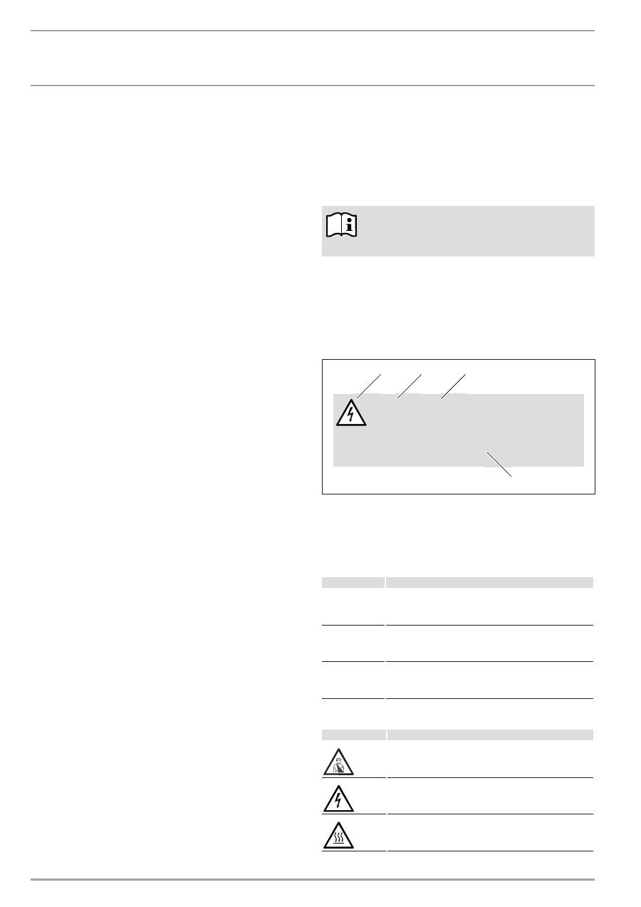
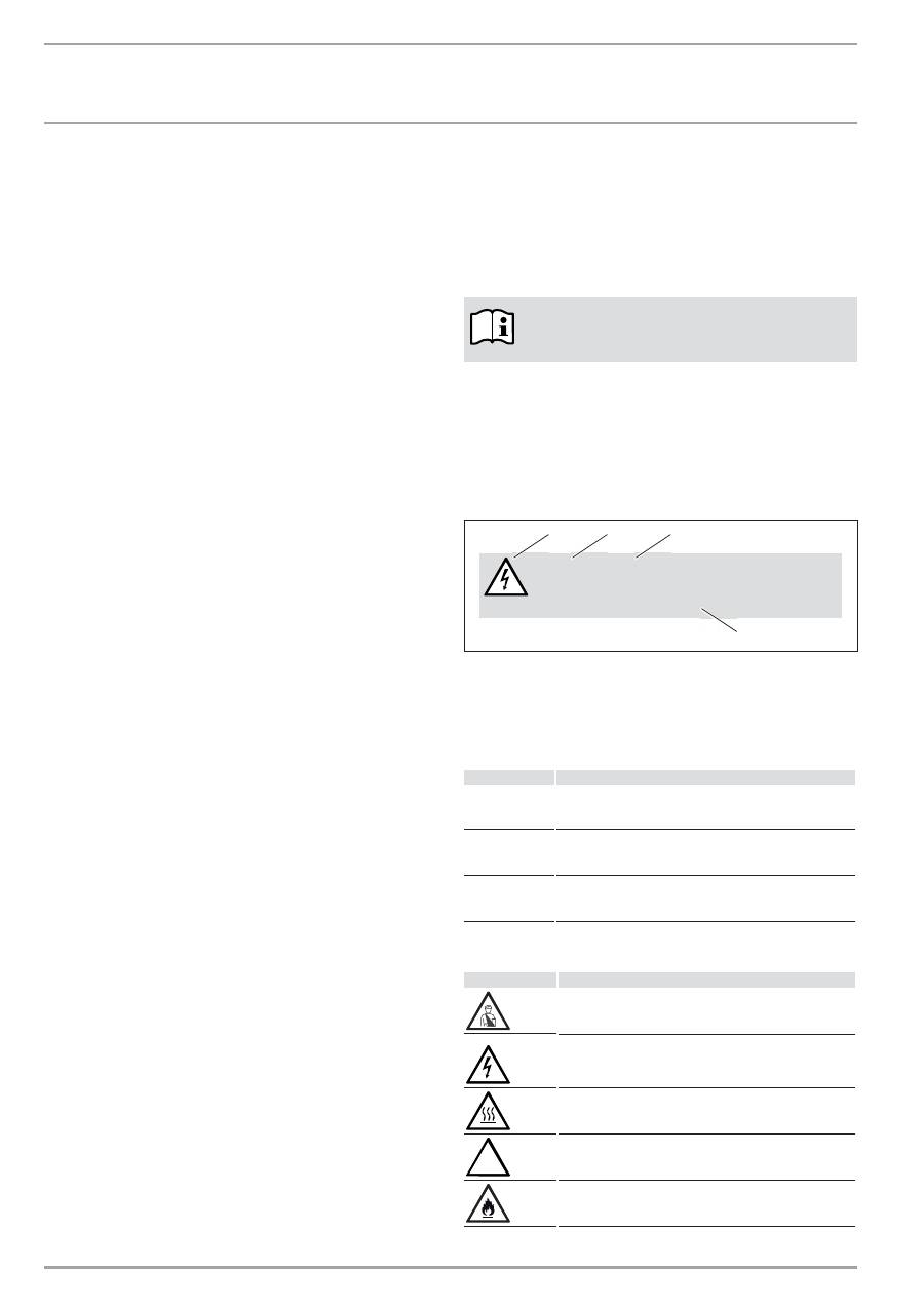
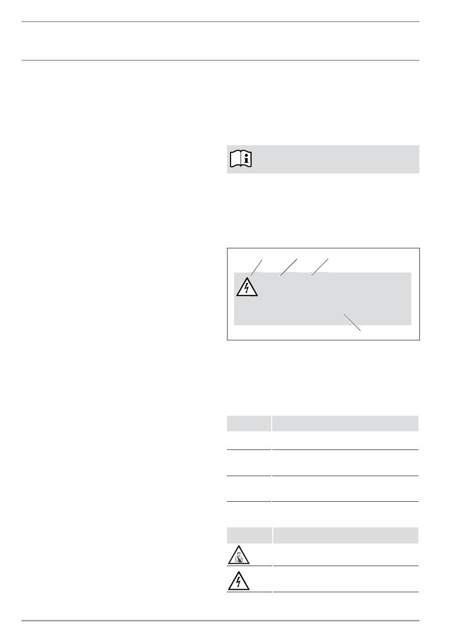
1.2.1 Aufbau
Sicherheitshinweis
Sicherheitshinweise bestehen aus einem Warnsymbol, einem
Signalwort und einem Hinweistext. Die Sicherheitshinweise sind
grau hinterlegt.
Beispiel:
GEFAHR Stromschlag
Bringen Sie das Gerät so an, dass Schalt- und
Regelvorrichtungen nicht von einer in der Bade-
wanne oder unter der Dusche befindlichen Person
berührt werden können.
1
2
3
4
1 Symbol (siehe Kapitel Warnsymbole/Symbole)
2 Signalwort (siehe Kapitel Signalworte)
3 Bennenung (siehe Kapitel Warnsymbole/Symbole)
4 Hinweistext
1.2.2 Signalworte
6,*1$/:257
%HGHXWXQJ
GEFAHR
Das Signalwort GEFAHR kennzeichnet Hinweise, deren
Nichtbeachtung schwere Verletzungen oder Tod zur Folge
haben.
WARNUNG
Das Signalwort WARNUNG kennzeichnet Hinweise, deren
Nichtbeachtung schwere Verletzungen oder Tod zur Folge
haben können.
VORSICHT
Das Signalwort VORSICHT kennzeichnet Hinweise, deren
Nichtbeachtung zu mittelschweren oder leichten Ver-
letzungen führen können.
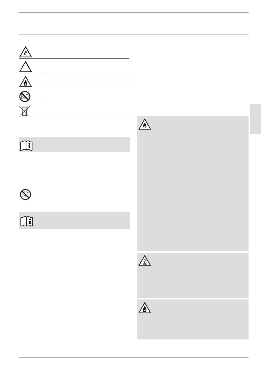
1.2.3 Warnsymbole/Symbole
:DUQV\PERO
%HQQHQQXQJ
Verletzung
Stromschlag
Verbrennung oder Verbrühung
BEDIENUNG
1. Allgemeine
Hinweise
___________________________________________2
1.1 Dokumentinformation
_____________________________________________ 2
1.2 Zeichenerklärung
___________________________________________________ 2
2. Sicherheit
________________________________________________________3
2.1 Bestimmungsgemäße
Verwendung
____________________________ 3
2.2 Sicherheitshinweise
________________________________________________ 3
2.3 Prüfzeichen
__________________________________________________________ 4
3. Gerätebeschreibung ____________________________________________4
3.1 Typenreihe
CNS-SE
_________________________________________________ 4
3.2 Typenreihe
CNS-UE
________________________________________________ 4
4. Bedienung
______________________________________________________4
4.1 Gerät einschalten und ausschalten _____________________________ 4
4.2 Beschreibung der Bedienoberfläche ___________________________ 4
4.3 Komfort-Betrieb
____________________________________________________ 4
4.4 ECO-Betrieb
__________________________________________________________ 4
4.5 Frostschutz___________________________________________________________ 4
4.6 Automatik
____________________________________________________________ 4
4.7 Begrenzung des Temperaturreglers ____________________________ 5
4.8 Außerbetriebnahme
_______________________________________________ 5
5. Reinigung,
Pflege
und Wartung _______________________________5
6.
Was tun wenn ... ________________________________________________5
INSTALLATION
7. Sicherheit
________________________________________________________6
7.1 Allgemeine
Sicherheitshinweise
________________________________ 6
7.2 Vorschriften, Normen und Bestimmungen ____________________ 6
8. Gerätebeschreibung ____________________________________________6
8.1 Lieferumfang
________________________________________________________ 6
9. Montage
_________________________________________________________6
10. Störungsbehebung
_____________________________________________7
11. Übergabe
des Gerätes _________________________________________7
12. Technische
Daten
_______________________________________________8
12.1 Abmaße Wandhängende Variante ______________________________ 8
12.2 Datentabelle CNS-SE _______________________________________________ 9
12.3 Datentabelle CNS-UE ______________________________________________ 9
KUNENDIENST UND GARANTIE
UMWELT UND RECYCLING
%(',(181*
6,&+(5+(,7
:::67,(%(/(/7521&20
&166(8(_
'(
8
76&
+
!
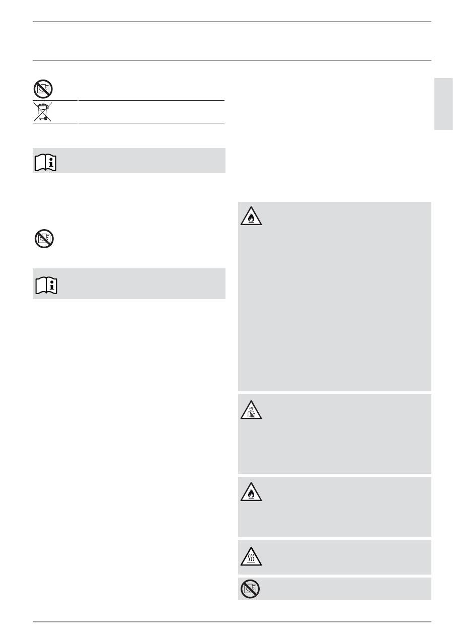
andere Situationen
Brand
Gerät nicht abdecken
Geräteentsorgung
1.2.4 Textzeichen und Formate in dieser Dokumentation
Lesen Sie Texte neben diesem Bildzeichen sorgfältig
durch.
»
Diese Passagen und das „
»
“ Symbol zeigen Ihnen, dass Sie
etwas tun müssen. Die erforderlichen Handlungen werden
Schritt für Schritt beschrieben.
— Passagen mit diesem „
–
“ Symbol zeigen Ihnen Aufzählungen.
1.2.5 Hinweise am Gerät
Gerät nicht abdecken!
1.2.6 Maßeinheiten
Die Maße in diesem Dokument sind in mm angegeben.
Abweichende Maßeinheiten werden jeweils extra an-
gegebenen.
2. Sicherheit
2.1 Bestimmungsgemäße
Verwendung
Das Gerät dient zur Erwärmung von Wohn räumen.
Eine andere oder darüber hinausgehende Benutzung gilt als nicht
bestimmungsgemäß. Zum bestimmungsgemäßen Gebrauch ge-
hört auch das Beachten dieser Anleitung. Bei Änderungen oder
Umbauten am Gerät erlischt jegliche Gewährleistung!
2.2 Sicherheitshinweise
Betreiben Sie das Gerät nur komplett installiert und mit allen
Sicherheitseinrichtungen.
WARNUNG Brand
Betreiben Sie das Gerät nicht ...
—
wenn die Räume durch Chemikalien, Staub, Gase
oder Dämpfe feuer- oder explosionsgefährdet
sind.
—
in unmittelbarer Nähe von Leitungen oder Behält-
nissen, die brenn bare oder explosionsge fährdete
Stoffe führen oder enthalten.
—
wenn im Aufstellraum Arbeiten wie Verlegen,
Schleifen, Versiegeln, durchgeführt werden.
—
wenn mit Benzin Sprays, Bohnerwachs oder Ähn-
lichem umgegangen wird. Lüften Sie den Raum vor
dem Heizen ausreichend.
—
wenn die Mindestabstände zu angrenzenden
Objektflächen wie zum Beispiel Möbel, Gardinen,
Vorhänge und Textilien oder sonstige brennbaren
Materialien unterschritten werden (Mindest-
abstände siehe Kapitel Technische Daten).
—
wenn ein Gerätebauteil beschädigt ist, das Gerät
heruntergefallen ist oder bereits eine Fehlfunktion
vorlag.
WARNUNG Verletzung
Sollten Kinder oder Personen mit eingeschränkten
körperlichen, sensorischen oder geistigen Fähigkeiten
das Gerät bedienen, stellen Sie sicher, dass dies nur
unter Aufsicht oder nach entsprechender Einweisung
durch eine für ihre Sicherheit zuständige Person ge-
schieht.
Beaufsichtigen Sie Kinder, um sicherzustellen, dass sie
nicht mit dem Gerät spielen!
WARNUNG Brand
Auf dem Gerät oder in dessen unmittelbarer Nähe
dürfen keine brennbaren, entzündbaren oder wärme-
dämmenden Gegenstände oder Stoffe, wie Wäsche,
Decken, Zeitschriften, Behälter mit Bohnerwachs oder
Benzin, Spraydosen und dergleichen gelegt werden.
WARNUNG Verbrennung
Die Gehäuseoberflächen des Gerätes und die aus-
tretende Luft werden bei Betrieb heiß (über 80 °C).
%(',(181*
*(5g7(%(6&+5(,%81*
_&166(8(
:::67,(%(/(/7521&20
VORSICHT Überhitzung
Gerät nicht abdecken.
Treten Sie nicht auf das Gerät.
CE-Kennzeichnung
Die CE-Kennzeichnung belegt, dass das Gerät alle grundlegenden
Anforderungen erfüllt:
— Richtlinie über die elektromagnetische Verträglichkeit
— Niederspannungsrichtlinie
2.3 Prüfzeichen
Siehe Typenschild.
Das Typenschild befindet sich rechts außen am Gerät.
3. Gerätebeschreibung
Das Gerät ist ein Elektro-Direktheizgerät ausschließlich zur Wand-
montage.
Das Gerät eignet sich zum Beispiel als Vollheizung oder als Über-
gangs- und Ergänzungsheizung für kleinere Räume wie zum Bei-
spiel Hobbyraum und Gästezimmer.
Die Luft im Gerät wird durch einen Heizkörper erwärmt und tritt
über die natürliche Konvektion oben durch das Luftaustrittgitter
aus. Durch die in der Geräteunterseite vorhandenen Öffnungen
strömt kühle Raumluft nach.
3.1 Typenreihe
CNS-SE
Nach der Wandbefestigung und elektrischem Anschluss mittels
Netzstecker ist das Gerät betriebsbereit.
3.2 Typenreihe
CNS-UE
Nach der Wandbefestigung und elektrischem Anschluss mittels
Festanschluss über eine Geräte-Anschlussdose ist das Gerät be-
triebsbereit.
4. Bedienung
4.1
Gerät einschalten und ausschalten
»
Schalten Sie das Gerät über den Schalter auf der rechten Seite
des Gerätes ein und aus.
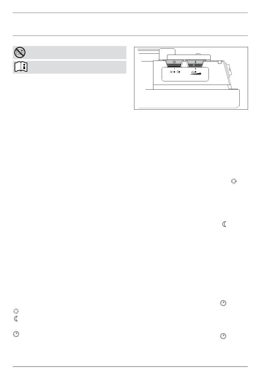
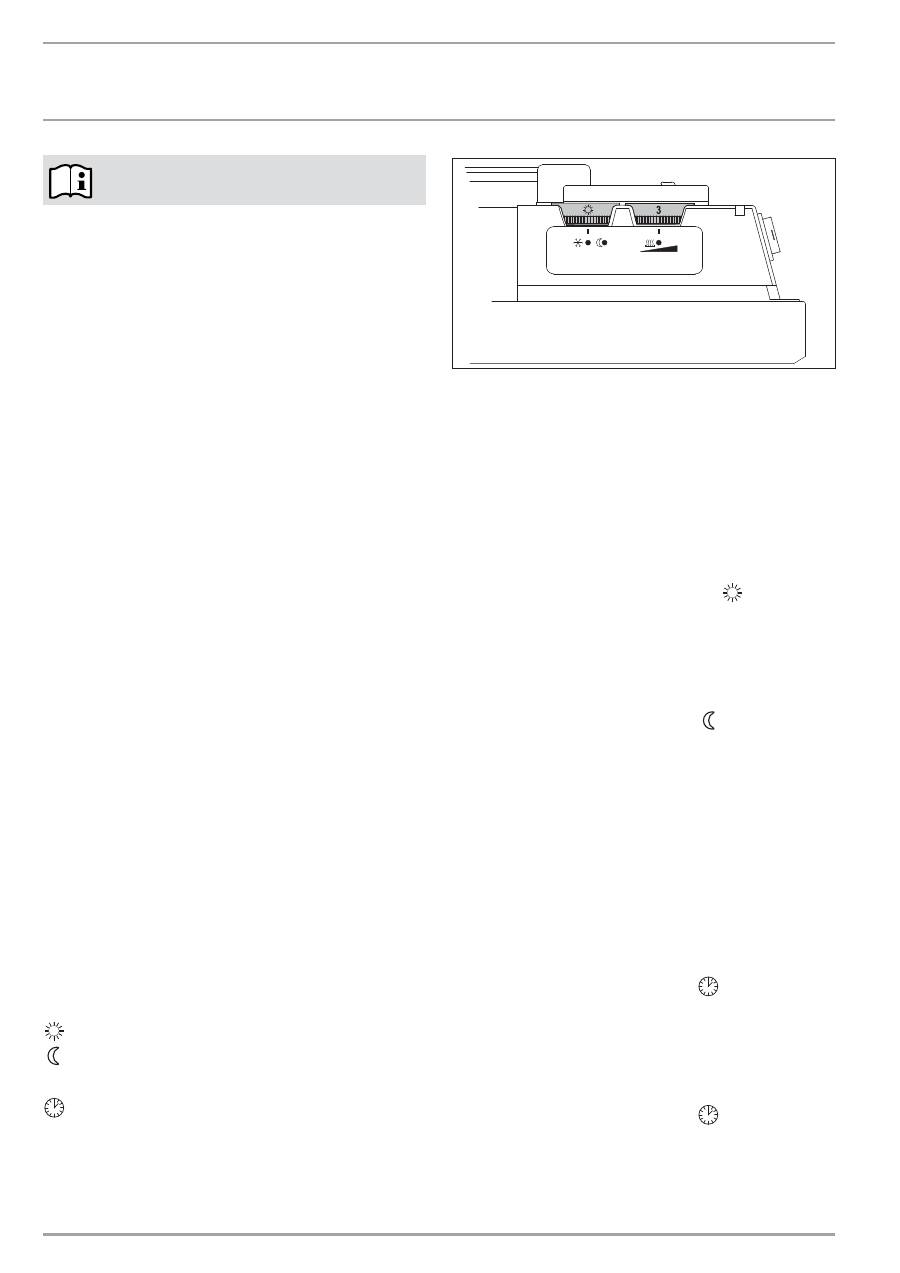
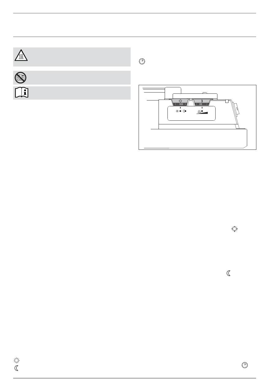
4.2
Beschreibung der Bedienoberfläche
»
Am Betriebsschalter können Sie folgende 4 Funktionen an-
wählen:
Komfort-Betrieb
ECO-Betrieb (Nachtabsenkung)
e
Frostschutz
Automatik
»
Stellen Sie über den Temperatur-Wählknopf die gewünschte
Raumtemperatur stufenlos ein (Temperaturwerte siehe Kapitel
Technische Daten).
26
_0
7
_3
1
_0
1
7
4
Sobald die eingestellte Raumtemperatur erreicht ist, wird diese
durch zeitweises Heizen konstant auf der eingestellten Temperatur
gehalten (die Heizleistung des Gerätes muss hierbei mindestens
dem benötigten Wärmebedarf des Raumes entsprechen).
Sind mehrere Geräte in einem Raum vorhanden, kann die Ein-
stellung am Temperatur-Wählknopf an jedem Gerät unterschied-
lich sein.
Um bei geöffneten Fenstern einen zu hohen Stromverbrauch zu
vermeiden, sollten Sie das Gerät während des Lüftens ausschalten.
4.3 Komfort-Betrieb
»
Stellen Sie den Betriebsschalter auf Komfort-Betrieb
.
In dieser Stellung schaltet die Heizung ab, sobald die am
Temperatur-Wählknopf eingestellte Raumtemperatur erreicht ist.
Die Raumtemperatur wird dann durch zeitweises Heizen konstant
gehalten.
4.4 ECO-Betrieb
»
Stellen Sie den Betriesschalter auf ECO-Betrieb
.
In dieser Stellung wird die am Temperatur-Wählknopf eingestellte
Komfort-Temperatur automatisch um 3°C vermindert.
4.5 Frostschutz
»
Stellen Sie den Betreibsschalter auf Frostschutz
e
.
In dieser Stellung schaltet der Temperaturregler die Heizung
automatisch ein, falls die Raumtemperatur unter die Frostschutz-
temperatur absinkt.
4.6 Automatik
4.6.1 Typenreihe
CNS-SE
»
Stellen Sie den Betriebsschalter auf Automatik
.
In dieser Stellung heizt das Gerät 120 Minuten im Komfort-Betrieb
und schaltet dann automatisch in die Frostschutzfunktion.
4.6.2 Typenreihe
CNS-UE
»
Stellen Sie den Betriebsschalter auf Automatik
.
Wenn das Gerät an ein optionales Steuergerät angeschlossen ist,
können Sie es darüber bedienen. Entsprechend der Einstellung
des Steuergerätes heizt das Gerät zu gewissen Tageszeiten im
Komfort-, ECO- oder Frostschutzbetrieb.
%(',(181*
5(,1,*81*3)/(*(81':$5781*
:::67,(%(/(/7521&20
&166(8(_
'(
8
76&
+
Wenn das Gerät nicht an ein Steuergerät angeschlossen ist, heizt
das Gerät im Komfort-Betrieb.
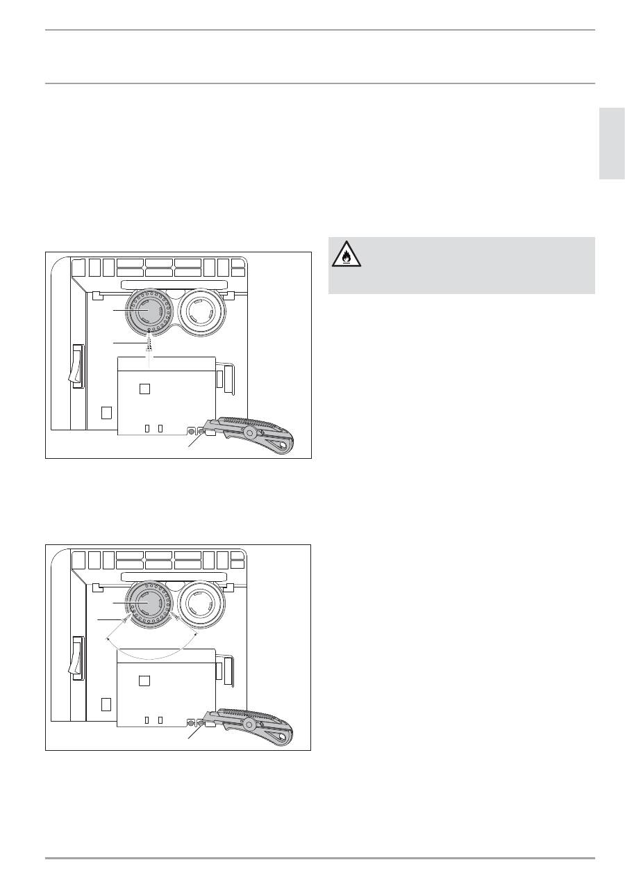
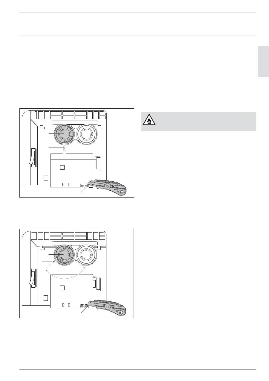
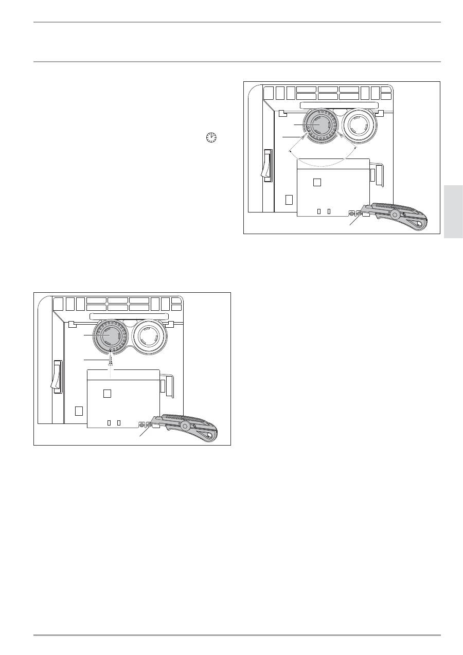
4.7
Begrenzung des Temperaturreglers
Mit den beiden an der Rückseite des Schaltgehäuses angebrachten
Stiften können Sie den Temperaturregler auf eine bestimmte Ein-
stellung fixieren oder den Temperatur-Einstellbereich begrenzen.
»
Brechen Sie die Stifte heraus.
»
Um die eingestellte Temperatur zu fixieren, stecken Sie einen
Stift in das gegenüberliegende Loch (siehe Bild).
2
6
_0
7
_3
1
_0
1
7
2
2
1
1
1
1 Stift
2 Temperatur-Wähler
»
Um den Temperatur-Einstellbereich zu begrenzen, stellen Sie
jeweils den Minimalwert und Maximalwert am Temperatur-
Wählknopf ein und stecken jeweils den Stift in ein etwas versetzt
gegenüberliegendes Loch (siehe Bild).
2
6
_0
7
_3
1
_0
1
7
3
2
1
1
1
1 Stift
2 Temperatur-Wähler
4.8 Außerbetriebnahme
»
Stellen Sie den Schalter rechts am Gerät auf AUS.
5. Reinigung, Pflege und Wartung
Sollten am Gerätegehäuse leichte bräunliche Verfärbungen auf-
treten, reiben Sie diese möglichst sofort mit einem feuchten Tuch
ab. Reinigen Sie das Gerät in kaltem Zustand mit gebräuchlichen
Pflegemitteln. Vermeiden Sie scheuernde und ätzende Pflege-
mittel.
VORSICHT Brand
Sprühen Sie kein Reinigungsspray in die Luftschlitze.
Achten Sie darauf, dass keine Feuchtigkeit in das Gerät
eindringt.
Bei den regelmäßigen Wartungen empfehlen wir, auch die
Kontroll- und Regelorgane überprüfen zu lassen. Spätestens 10
Jahre nach Erstinbetriebnahme sollten Sicherheits-, Kontroll- und
Regelorgane durch den Fachhandwerker überprüft werden.
6. Was tun wenn ...
... das Gerät nicht heizt:
Überprüfen Sie die eingestellte Temperatur am Gerät und die
Sicherung in der Hausinstallation.
Das Gerät besitzt einen Schutztemperaturregler, der bei Über-
hitzung das Gerät abschaltet. Nach Beseitigung der Ursache (zum
Beispiel verdeckte Luftaus- oder -eintrittsöffnung) geht das Gerät
nach einer Abkühlzeit von wenigen Minuten wieder in Betrieb.
Können Sie den Fehler nicht beheben, rufen Sie den Fachhand-
werker. Zur besseren und schnelleren Hilfe teilen Sie ihm die
Nummer (Nr. XXXXXX - XXXX - XXXXXX) vom Typenschild mit:
_&166(8(
:::67,(%(/(/7521&20
,167$//$7,21
6,&+(5+(,7
7. Sicherheit
Die Installation, Inbetriebnahme sowie Wartung und Reparatur
des Gerätes darf nur von einem Fachhandwerker durchgeführt
werden.
7.1 Allgemeine
Sicherheitshinweise
Wir gewährleisten eine einwandfreie Funktion und Betriebssicher-
heit nur, wenn das für das Gerät bestimmte Original-Zubehör und
die originalen Ersatzteile verwendet werden.
GEFAHR Stromschlag
Bringen Sie das Gerät bei der Wandmontage so an,
dass Schalt- und Regelvorrichtungen nicht von einer
in der Badewanne oder unter der Dusche befindlichen
Person berührt werden können.
!
VORSICHT
—
Bringen Sie das Wandgerät nur an einer senk-
rechten, bis mindestens 85 °C temperatur-
beständigen Wand an.
—
Halten Sie die Mindestabstände zu angrenzenden
Objektflächen ein (Mindestabstände siehe Kapitel
Technische Daten).
—
Bringen Sie das Gerät nicht unmittelbar unter
einer Wandsteckdose an.
—
Achten Sie darauf, dass die Anschlussleitung keine
Geräteteile berührt.
7.2
Vorschriften, Normen und Bestimmungen
Beachten Sie alle nationalen und regionalen Vor-
schriften und Bestimmungen zur Installation, Montage
und Inbetriebnahme.
8. Gerätebeschreibung
8.1 Lieferumfang
— Wandhalterung (am Gerät eingehängt)
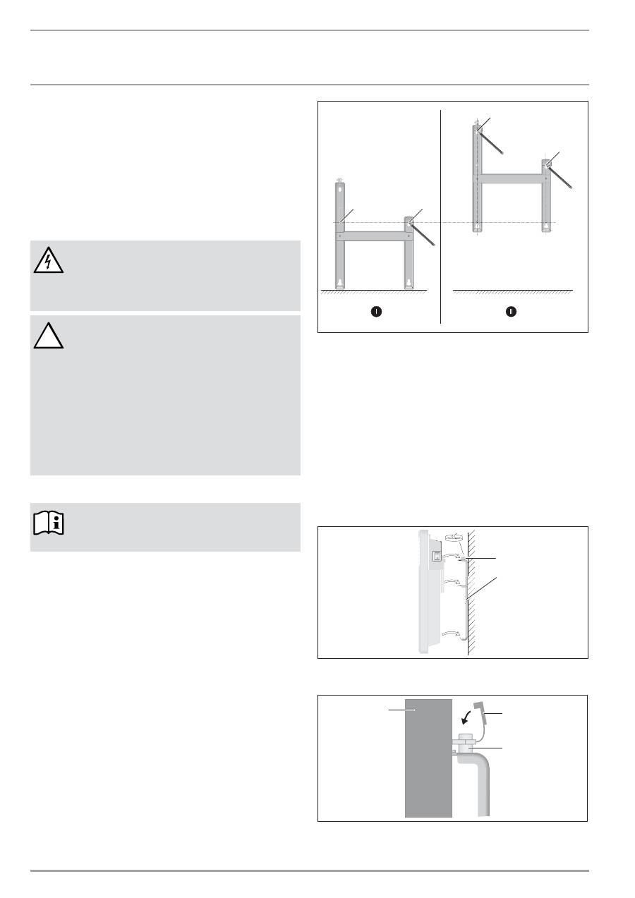
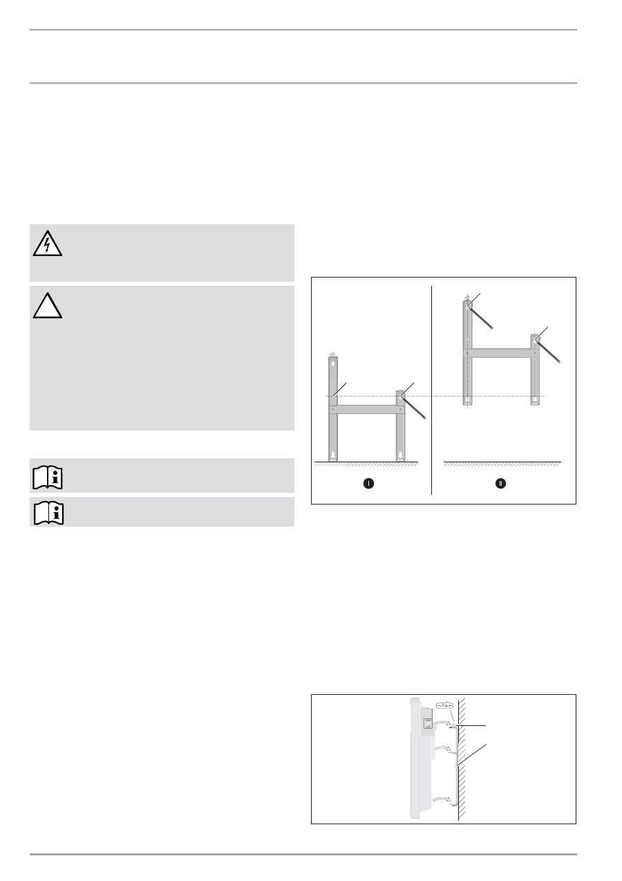
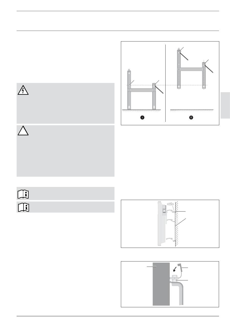
9. Montage
9.1 Montage
der
Wandhalterung
Sie können die Wandhalterung auch als Schablone zur Wand-
befestigung verwenden, dies gewährleistet den notwendigen
Bodenabstand.
»
Hängen Sie die Wandhalterung aus.
»
Stellen Sie die mittelpunktorientier te Wandhalterung
waagerecht auf den Boden und kennzeichnen Sie die Bohrungen
Punkt 1 und 2.
»
Heben Sie die Wandhalterung hoch, so dass die unteren
Bohrungen in der Wandhalterung deckungsgleich mit den
gerade angebrachten Kennzeichnungen an der Montagewand
sind.
»
Kennzeichnen Sie die Bohrungen 3 und 4 an der Montagewand.
DDD
2
6
_0
7
_3
1
_0
1
2
4
1
3
2
4
»
Bohren Sie an allen 4 Kennzeichnungen Löcher. Befestigen Sie
die Wandhalterung mit geeigneten Materialien (Schrauben,
Dübel) je nach Wandart. Mit den vertikalen Langlöchern können
Sie ein Verlaufen der Befestigungsbohrung ausgleichen.
9.2
Montage des Gerätes
»
Hängen Sie das Gerät mit den Aufnahmeschlitzen in der Geräte-
rückseite gleichzeitig auf die vier Laschen der Wandhalterung.
»
Drücken Sie das Gerät zur Arretierung an.
»
Drehen Sie den Verschlussbolzen der Wandhalterung im Uhr-
zeigersinn bis zum Anschlag. Damit ist die Befestigung verriegelt.
»
Drücken Sie die Sicherungskappe auf den Verschlussbolzen,
damit dieser sich nicht mehr zurückdrehen lässt.
26
_0
7
_3
1
_0
03
5
1
2
1 Verschlussbolzen
2 Wandhalterung
2
6
_0
7
_3
1
_0
1
2
7
1
2
3
1 Gerät
2 Sicherungskappe
:::67,(%(/(/7521&20
&166(8(_
'(
8
76&
+
,167$//$7,21
67581*6%(+(%81*
3 Verschlussbolzen
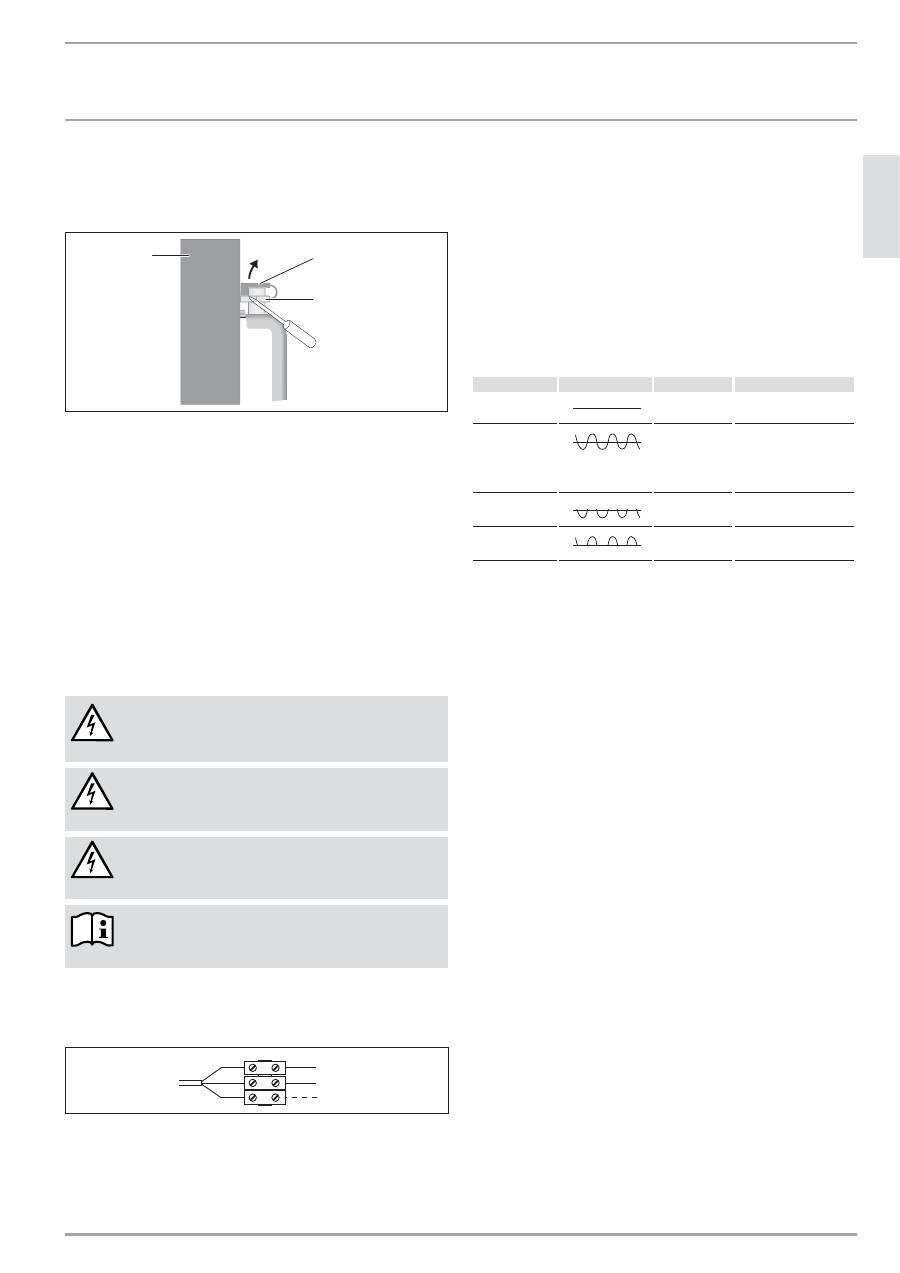
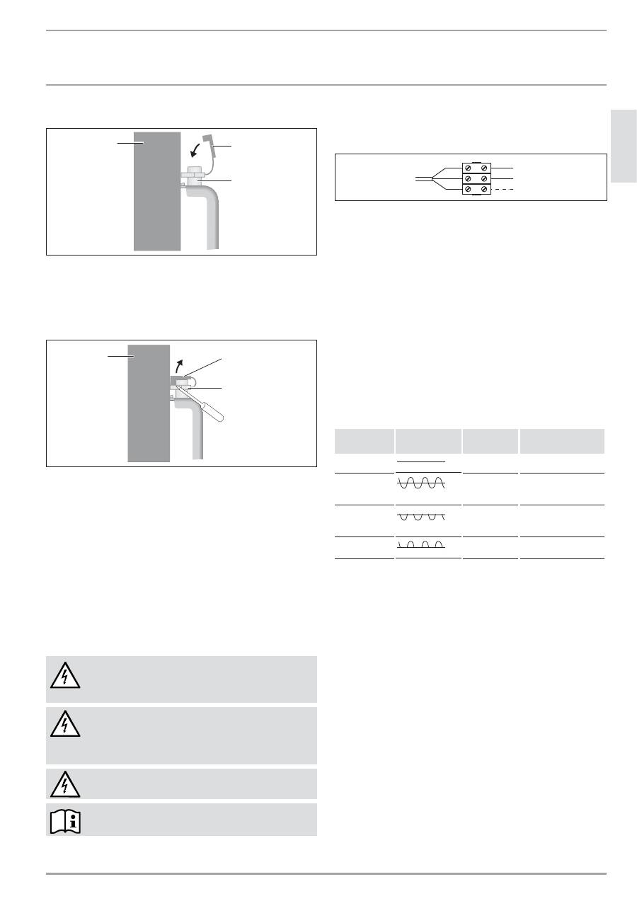
9.3
Demontage des Gerätes
»
Lösen Sie die Sicherungskappe vom Verschlussbolzen.
26
_0
7
_3
1
_0
1
2
8
1
2
3
1 Gerät
2 Sicherungskappe
3 Verschlussbolzen
»
Lösen Sie den Verschlussbolzen der Wandhalterung entgegen
dem Uhrzeigersinn.
»
Heben Sie das Gerät leicht an und nehmen Sie es nach vorn von
der Wandhalterung ab.
9.4 Elektrischer
Anschluss
»
Achten Sie auf ausreichenden Zuleitungsquerschnitt bauseits.
»
Achten Sie darauf, dass im Abstand von mindestens 10 cm seit-
lich vom Gerät eine Steckdose oder Geräte-Anschlussdose für
Festanschluss installiert ist.
GEFAHR Stromschlag!
Führen Sie alle elektrischen Anschluss- und
Installationsarbeiten nach Vorschrift aus.
GEFAHR Stromschlag!
Das Gerät muss über eine Trenn strecke von mindestens
3 mm allpolig vom Netz getrennt werden können.
GEFAHR Stromschlag!
Die Installation mit festverlegter Anschlussleitung ist
nicht zulässig.
Beachten Sie das Typenschild. Die angegebene
Spannung muss mit der Netzspannung überein-
stimmen.
Typenreihe CNS-UE
»
Schließen Sie die dreiadrige Leitung bei Festanschluss wie folgt
an einer Geräteanschlussdose an.
1
2
1
2
3
3
2
6
_0
7
_3
1
_0
1
7
5
1 Nulleiter = blau
2 Phase = braun
3 Steuerleitung = schwarz
Sie haben folgende 3 Möglichkeiten das Gerät anzuschließen:
1 Geräteanschluss ohne Steuerleitung:
Nicht gesteuertes Gerät. Die Steuerleitung ist nicht angeschlossen.
Isolieren Sie in diesem Fall die Steuerleitung.
2 Temperaturabsenkung über die Steuerleitung:
Zur Absenkung der am Thermostaten eingestellten Temperatur
(um 3°C) wird die schwarze Steuerleitung über einen externen
elektronischen Kontakt, z.B. über eine Zeitschaltuhr angesteuert.
3 Anschluss der Steuerleitung an ein Steuergerät:
Sie können das Gerät an jedes Steuergerät anschließen, welches
die in nachfolgender Tabelle aufgeführten Signalformen als
Steuersignal ausgibt.
%HIHKO
2V]LOORVNRS
%HWUHLEVDUW +HL]WHPSHUDWXU
Kein Strom
Komfort-
Betrieb
Je nach der Einstellung
des Thermostaten
Komplett-
schwingung
230 V
ECO-Betrieb
Absinken um 3°C
im Verhältnis zur
Einstellung des
Thermostaten
Halbschwingung
Negativ - 230 V
Frostschutz-
Betrieb
Frostschutztemperatur
Halbschwingung
Positiv + 230 V
Stop
Keine
10. Störungsbehebung
Die Netzanschlussleitung darf bei einem Austausch nur von einem
Fachhandwerker mit Original Ersatzteilen von uns ersetzt werden.
11. Übergabe des Gerätes
Erklären Sie dem Benutzer die Funktionen des Gerätes. Machen
Sie ihn besonders auf die Sicherheitshinweise aufmerksam. Über-
reichen Sie dem Benutzer die Bedienungs- und Installations-
anleitung.
_&166(8(
:::67,(%(/(/7521&20
,167$//$7,21
7(&+1,6&+('$7(1
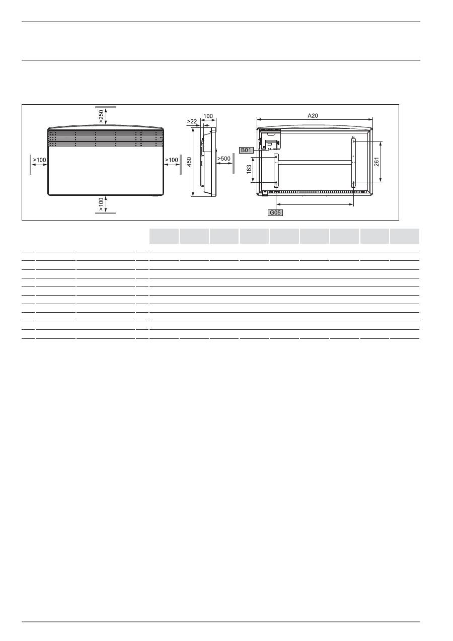
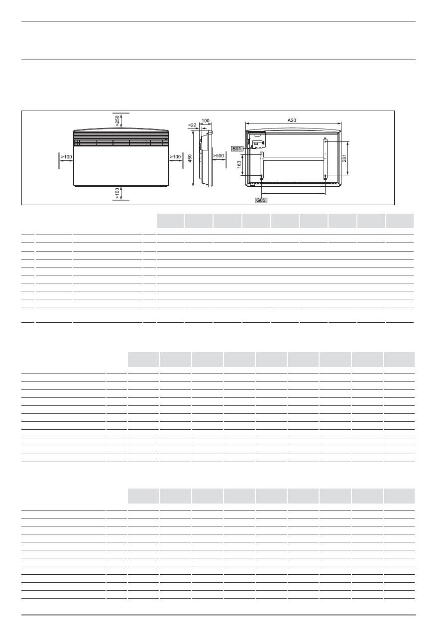
12. Technische Daten
12.1 Abmaße Wandhängende Variante
8
0
_0
7
_3
1
_000
9
&16
6(8(
&16
6(8(
&16
6(8(
&16
6(8(
&16
6(8(
&16
6(8(
&16
6(8(
&16
6(8(
&16
6(8(
A10 Gerät
Höhe
mm
450
A20 Gerät
Breite
mm
370
445
445
590
590
740
740
890
1040
A30 Gerät
Tiefe
mm
100
A50 Gerät
Mindestabstand oben
mm
250
A51
Gerät
Mindestabstand unten mm
100
A52 Gerät
Mindestabstand rechts mm
100
A53 Gerät
Mindestabstand links
mm
100
A54 Gerät
Mindestabstand vorne mm
500
A55 Gerät
Mindestabstand hinten mm
22
B01 Durchführung für elektr. Leitungen
G05 Wandhalterung Lochabstand
mm
121
195
195
343
343
491
491
639
787
:::67,(%(/(/7521&20
&166(8(_
'(
8
76&
+
,167$//$7,21
7(&+1,6&+('$7(1
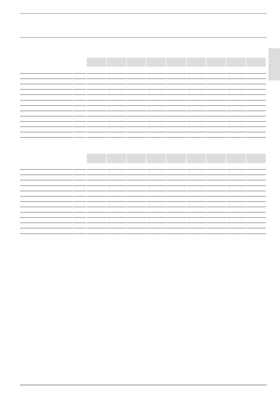
12.2 Datentabelle
CNS-SE
&16
6(
&16
6(
&16
6(
&16
6(
&16
6(
&16
6(
&16
6(
&16
6(
&16
6(
229740
229741
229742
229743
229744
229745
229746
229747
229748
Anschlussleistung
kW
0,5
0,75
1,0
1,25
1,5
1,75
2,0
2,5
3,0
Einstellbereich
°C
6-30
6-30
6-30
6-30
6-30
6-30
6-30
6-30
6-30
Frostschutzstellung
°C
7
7
7
7
7
7
7
7
7
Elektroanschluss
1/N~230 V
1/N~230 V
1/N~230 V
1/N~230 V
1/N~230 V
1/N~230 V
1/N~230 V
1/N~230 V
1/N~230 V
Leistungsstufen
Höhe
mm
450
450
450
450
450
450
450
450
450
Breite
mm
370
445
445
590
590
740
740
890
1040
Tiefe
mm
100
100
100
100
100
100
100
100
100
Gewicht
kg
3,8
4,4
4,4
5,7
5,7
6,8
6,8
8,1
9,4
Schutzart (IP)
IP24
IP24
IP24
IP24
IP24
IP24
IP24
IP24
IP24
Schutzklasse
II
II
II
II
II
II
II
II
II
Farbe
alpineweiß alpineweiß alpineweiß alpineweiß alpineweiß alpineweiß alpineweiß alpineweiß alpineweiß
12.3 Datentabelle
CNS-UE
&16
8(
&16
8(
&16
8(
&16
8(
&16
8(
&16
8(
&16
8(
&16
8(
&16
8(
229749
229750
229751
229752
229753
229754
229755
229756
229757
Anschlussleistung
kW
0,5
0,75
1,0
1,25
1,5
1,75
2,0
2,5
3,0
Einstellbereich
°C
6-30
6-30
6-30
6-30
6-30
6-30
6-30
6-30
6-30
Frostschutzstellung
°C
7
7
7
7
7
7
7
7
7
Elektroanschluss
1/N~230 V
1/N~230 V
1/N~230 V
1/N~230 V
1/N~230 V
1/N~230 V
1/N~230 V
1/N~230 V
1/N~230 V
Leistungsstufen
Höhe
mm
450
450
450
450
450
450
450
450
450
Breite
mm
370
445
445
590
590
740
740
890
1040
Tiefe
mm
100
100
100
100
100
100
100
100
100
Gewicht
kg
3,3
4
4
5,2
5,2
6,3
6,3
7,7
8,9
Schutzart (IP)
IP24
IP24
IP24
IP24
IP24
IP24
IP24
IP24
IP24
Schutzklasse
II
II
II
II
II
II
II
II
II
Farbe
alpineweiß alpineweiß alpineweiß alpineweiß alpineweiß alpineweiß alpineweiß alpineweiß alpineweiß

_&166(8(
:::67,(%(/(/7521&20
*(50$1<
.81'(1',(16781'*$5$17,(
&:77>00498,70490&>G<?92,904908?9=0<0<$<:/?6>0,?1><0>09
=>0309A4<39099,>H<74.384>%,>?9/',>C?<&04>0
%?109&40?9=,9
I 849-049<?109,?=/08/0?>=.3090=>
90>C",B48,7I 849-049<?109,?=":-471?9690>C09
:/0<=.3<04-09&40?9=
&>40-077><:98-:
?9/09/409=>
H<=>09-0<20<&><,D0:7C849/09
",476?9/09/409=>=>40-0707><:9/0
,BI 849,?=/08/0?>=.3090=>90>C
",B48,7I 849-049<?109,?=":-471?9690>C09
*04>0<09=.3<41>09=49/,?1/0<70>C>09&04>0,?1201H3<>
(9=0<09 ?9/09/409=>0<<04.309&40>0701:94=.3<?9/?8/40(3<
,?.3,9&,8=>,209?9/&:99>,209=:A40,9040<>,209 ?9/09
/409=>049=F>C00<1:7209AF3<09/?9=0<0<0=.3F1>=C04>09@:9
-4=(3<1<04>,2=-4=(3<7=&:9/0<=0<@4.0-40>09
A4< ?9/09/409=>049=F>C0-4=(3<H</40=09&:9/0<=0<@4.0
=:A40 ?9/09/409=>049=F>C0,9&,8=&:99?9/040<>,209
A0</093G30<0$<04=0-0<0.390>
40=0,<,9>40-0/492?9209<02079C?=F>C74.30,<,9>40704=>?9209
@:9?9=20209H-0</089/6?9/09&40><0>0990-09/4020=0>C
74.3090AF3<704=>?92=,9=;<H.30/0= ?9/094020=0>C74.309
0AF3<704=>?92=,9=;<H.3020209H-0</09=:9=>4209)0<><,2=
;,<>90<9=49/94.3>-0<H3<>
40=0,<,9>40-0/492?9209207>099?<1H<=:7.300<F>0/40@:8
9/6?9/0949/0<?9/0=<0;?-7460?>=.37,9/,7=#0?20<F>0
0<A:<-09A0</0949,<,9>40@0<><,26:88>94.3>C?=>,9/0
=:A04>/0<9/6?9/004920-<,?.3>0=0<F>:/0<04990?0=0<F>
=0490<=04>=@:904908,9/0<099/6?9/090<A4<->
40,<,9>40704=>?92A4</0<-<,.3>A099,9?9=0<090<F>09049
0<=>077?92=?9/ :/0<",>0<4,710370<4990<3,7-/0<,<,9>40
/,?0<,?1><4>>40,<,9>40?81,==>50/:.360490!04=>?92091H<
=:7.300<F>0,9/09090370<&.3F/09:/0<"F9207,?12<?9/
@:9)0<6,76?92.3084=.30<:/0<0706><:.3084=.30<49A4<6?92
10370<3,1>0<?1=>077?92-CA9=>,77,>4:9=:A40?9=,.3208FD0<
49<02?740<?920/409?92:/0<?9=,.3208FD0<9,9=;<?.3
9,380-CA)0<A09/?92,?1><0>09-09=:,?=20=.37:==09=49/
!04=>?9209,?12<?9/8,92073,1>0<:/0<?9>0<7,==090<*,<>?92
*4>>0<?92=049H==09:/0<=:9=>4209#,>?<0<=.3049?9209
40,<,9>400<74=.3>A099,80<F>%0;,<,>?<09492<4110:/0<
-F9/0<?9209/?<.394.3>@:9?9=,?>:<4=40<>0$0<=:909@:<
209:8809A?</09
40,<,9>40704=>?92?81,==>/40=:<21F7>420$<H1?92/0=0<F>0=
A:-04C?9F.3=>0<84>>07>A4</:-049,<,9>40,9=;<?.3-0=>03>
8,<,9>401,7709>=.304/09,77049A4<,?1A07.30<>/0<0370<
-03:-09A4</==>03>?9=1<040490%0;,<,>?</0=0<F>0=,?=
1H3<09C?7,==09:/0<=07-=>,?=C?1H3<09>A,420,?=20A0.3=07>0
'0470A0</09?9=0<4209>?8
H</40,?0<?9/%04.3A04>0/0<,<,9>40H-0<903809A4<=F8>
74.30",>0<4,7?9/":9>,206:=>09
&:A04>/0< ?9/0A0209/0=,<,9>401,770=,?12<?9/20=0>C
74.30<0AF3<704=>?92=,9=;<H.3020209,9/0<0)0<><,2=;,<>90<
!04=>?92090<3,7>093,>09>1F77>0490!04=>?92=;4.3>@:9?9=
&:A04> 0490 ,<,9>40704=>?92 0<-<,.3> A4</ H-0<903809 A4<
60490,1>?921H</400=.3F/42?920490=0<F>0=/?<.340-
=>,370?0<?1<?3<:/0<F3974.30(<=,.309
E-0</40@:<=>0309/C?20=,2>09,<,9>40704=>?9209349,?=20309/
6,99/0<9/6?9/09,.3/40=0<,<,9>40604909=;<H.30A0209
84>>07-,<0<&.3F/09:/0<:720=.3F/09/40/?<.3/,=0<F>@0<
?<=,.3>A0</0949=-0=:9/0<0,?1<=,>C,?D0<3,7-/0=0<F>0=
09>=>,9/090<&.3F/09207>09/8,.3090=0>C74.309=;<H.30
/0= ?9/09?9=20209H-0<:/0<20209H-0<<4>>09-704-09?9
-0<H3<>
H<48;<4@,>09,?=3,7>04920=0>C>00<F>0-0><F2>/40,<,9>40
/,?0<":9,>048H-<4209C?804=;407-040490849=,>C/0<
0<F>0490A0<-0,9/A0<6=:/0<9/?=><40-0><40-09-0><F2>
/40,<,9>40/,?0<":9,>0
40,<,9>40/,?0<-02499>1H<50/0=0<F>84>/0<E-0<2,-0/0=
0<F>0=,9/09 ?9/09/0</,=0<F>C?80<=>09",7049=0>C>
,<,9>40704=>?92091H3<0994.3>C?0490<)0<7F920<?92/0<,<,9
>40/,?0<?<.3/400<-<,.3>0,<,9>40704=>?92A4</6049090?0
,<,9>40/,?0<49,9220=0>C>40=247>1H<,7700<-<,.3>09,
<,9>40704=>?920949=-0=:9/0<01H<0>A,4204920-,?>0<=,>C>0470
:/0<1H</40<=,>C74010<?920490=90?090<F>0=
,<,9>40,9=;<H.30=49/@:<-7,?1/0<,<,9>40/,?0<4990<3,7-
@:9CA04*:.3099,.3/08/0<",92070<6,99>A?</0-04?9=
,9C?807/09,-048H==0992,-09C?80370<C?80<F>?9/
C?8+04>;?96>/0<0=>=>077?92208,.3>A0</097=,<,9>40
9,.3A04=4=>/40%0.39?92:/0<049=:9=>420</,>40<>0< ,?19,.3
A04=-04C?1H20903709/40@:<209,99>0992,-09:/0<(9>0<
7,209-0=>03>6049,<,9>40,9=;<?.3
!
*4< =49/ 94.3> @0<;4.3>0> ,<,9>40704=>?9209 ,?D0<3,7- /0<
?9/0=<0;?-7460?>=.37,9/C?0<-<4920904&>G<?92090490=
48?=7,9/04920=0>C>090<F>0=4=>/40=0=2020-09091,77=,?1
01,3<?9/ :=>09/0= ?9/09,9/09 ?9/09/409=>490?>=.3
7,9/C?=09/0940%H.6=09/?920<1:72>0-091,77=,?101,3<?9/
:=>09/0= ?9/09>A,42020=0>C74.309=;<H.30/0= ?9/09
?9=20209H-0<:/0<20209H-0<<4>>09-704-09,?.349/40=08
,77?9-0<H3<>
H<,?D0<3,7-0?>=.37,9/=0<A:<-0900<F>0247>/40=0,<,9>40
94.3>=207>09/4050A047420920=0>C74.309):<=.3<41>09?9/20
20-09091,77=/40!4010<-0/492?9209/0<!F9/0<20=077=.3,1>-CA
/0=8;:<>0?<=
:::67,(%(/(/7521&20
&166(8(_
'(
8
76&
+
*(50$1<
80:(/781'5(&<&/,1*
+(2'0$0:23,!$1"':#(&2!$(',$, ,)-++2' !$,5(0$1
1-0&%:*2(&4$0. ")2(22$'$*%$,($#($+5$*2731"'<27$,3,#
<!$0* 11$,($#($$0. ")3,&#$+ "'' ,#5$0)!75 "'' ,
#$*(0!$2$(*(&$,3,1&$+$(,1 ++(2#$+0-8' ,#$*3,##$+
"'' ,#5$0) "'' ,#$*(,$321"'* ,# ,$(,$+5(0)1 +$,
<"), '+$3,#,21-0&3,&1)-,7$.2%<0#($3+5$*21"'-,$,#$
3% 0!$(23,&#$0$0. ")3,&$,
+ '+$,#$1*$)20-3,#*$)20-,()&$0:2$&$1$27$1*$)20-
(12#($)-12$,*-1$<")& !$#($1$1$0:2$1!$('0$0)-++3, *$,
++$*12$**$&$5:'0*$(12$2
(0$012$**$01-0&$,(+ '+$,#$00-#3)24$0 ,25-023,&%<0
$(,$3+5$*2&$0$"'2$$' ,#*3,&3,#$05$023,&#$0*2&$0:2$
$(2$0$,%-0+ 2(-,$,$0' *2$,($<!$0'0$-++3,$-#$0'0$,
"'' ,#5$0)$0 "'':,#*$0
9!$0# 1<"), '+$1612$+5$0#$,'-'$$"6"*(,&/3-2$,#$0
2$0( *($,$00$("'23+$.-,($,3,##($+5$*273$,2* 1
2$, +(2*$(12$,5(0&$+$(,1 +$(,$,5("'2(&$,$(20 &73+
+5$*21"'327
$0$(21!$(#$0,25(")*3,&,$3$0$0:2$ "'2$,5(0 3%$(,$'-'$
$"6"*(,&%:'(&)$(2#$0 2$0( *($,($-0 311$273,&%<0$(,$
2$0( *($#$04$05$023,&1(,##($$"6"*(,&6+!-*$3,##($
4-,3,14-0&$,-++$,$$,,7$("',3,&, "'
3,# # +(2#($4$01"'($#$,$,3,1212-%%$&$
20$,,2&$1 ++$*25$0#$,);,,$,
,21-0&$,($#($1$1$0:2% "'3,#1 "'&$0$"'2, "'#$,;02*("'
&$*2$,#$,-01"'0(%2$,3,#$1$27$,
_&166(8(
:::67,(%(/(/7521&20
&217(176_23(5$7,21
*(1(5$/,1)250$7,21
1. General
information
1.1 Document
information
The chapter
Operation
is intended for users and heating
contractors.
The chapter
Installation
is intended for heating contractors.
Read these instructions carefully before using the
appliance and retain them for future reference. Pass
on the instructions to any new users.
1.2
Key to symbols
1.2.1 Layout of safety information
Safety information comprises a warning symbol, a keyword and
a text giving information. Safety information is printed on a grey
background.
Example:
DANGER Electrocution
Install the appliance in such a way that control
equipment...
1
2
3
4
1 Symbol (see chapter on warning symbols/symbols)
2 Keyword (see chapter on keywords)
3 Description (see chapter on warning symbols/symbols)
4 Information text
1.2.2 Keywords
.(<:25'
'HVFULSWLRQ
DANGER
The keyword DANGER indicates information which must be
observed, otherwise serious injury or death will result.
WARNING
The keyword WARNING indicates information that must be
observed, otherwise serious injury or death may result.
CAUTION
The keyword CAUTION indicates information that must be
observed, otherwise relatively serious or light injuries may
result.
1.2.3 Warning
symbols/symbols
:DUQLQJV\PERO 'HVFULSWLRQ
Injury
Electrocution
Burns or scalding
!
Other situations
Fire
OPERATION
1. General
information __________________________________________ 12
1.1 Document
information
___________________________________________ 12
1.2 Key to symbols _____________________________________________________ 12
2. Safety
__________________________________________________________ 13
2.1 Intended
use
________________________________________________________ 13
2.2 Safety
information
________________________________________________ 13
2.3 Test
symbols
________________________________________________________ 14
3. Appliance
description
________________________________________ 14
3.1 Series
CNS-SE
______________________________________________________ 14
3.2 Series
CNS-UE
______________________________________________________ 14
4. Operation
_____________________________________________________ 14
4.1 Switching the appliance on and off ____________________________ 14
4.2 Description of the user interface _______________________________ 14
4.3 Comfort
mode
______________________________________________________ 14
4.4 ECO
mode
___________________________________________________________ 14
4.5 Frost
protection
____________________________________________________ 14
4.6 Automatic
___________________________________________________________ 14
4.7 Limiting the temperature controller ___________________________ 15
4.8 Shutting
down
_____________________________________________________ 15
5.
Cleaning, care and maintenance ____________________________ 15
6.
What to do if ... _______________________________________________ 15
INSTALLATION
7. Safety
__________________________________________________________ 16
7.1 General safety instructions ______________________________________ 16
7.2 Instructions, standards and regulations ______________________ 16
8. Appliance
description
________________________________________ 16
8.1 Standard
delivery
__________________________________________________ 16
9. Installation
____________________________________________________ 16
9.1 Installing the wall mounting bracket __________________________ 16
9.2 Appliance
installation
____________________________________________ 16
9.3 Dismounting the appliance ______________________________________ 17
9.4 Power
supply
_______________________________________________________ 17
10. Troubleshooting_______________________________________________ 17
11. Appliance
handover
__________________________________________ 17
12. Specification
___________________________________________________ 18
12.1 Dimensions of wall mounted version __________________________ 18
12.2 Specification table CNS-SE ______________________________________ 18
12.3 Specification table CNS-UE ______________________________________ 18
ENVIRONMENT AND RECYCLING
CUSTOMER SERVICE AND WARRANTY
23(5$7,21
6$)(7<
:::67,(%(/(/7521&20
&166(8(_
(1
*/
,6
+
Never cover the appliance
Appliance disposal
1.2.4 Text symbols and layout in this documentation
Read the text next to this symbol carefully.
»
The "
»
" symbol indicates that you should do something. The
action you need to take is described step by step.
— Passages with the "
–
" symbol show you lists of items.
1.2.5 Information on the appliance
Never cover the appliance
1.2.6 Units of measurement
The dimensions in this document are given in mm.
Any alternative units of measurements are specified
accordingly.
2. Safety
2.1 Intended
use
This appliance is designed to heat living areas.
Any other use beyond that described shall be deemed inappropriate.
Observation of these instructions is also part of the correct use of
this appliance. Any modifications or conversions to the appliance
void all warranty rights.
2.2 Safety
information
Operate the appliance only when fully installed and with all safety
equipment fitted.
WARNING Fire
Never operate this appliance ...
—
in rooms where the appliance is at risk of fire or
explosion as a result of chemicals, dust, gases or
vapours.
—
in the direct proximity of pipes or receptacles that
carry or contain flammable or explosive materials.
—
if work such as laying cables, grinding or sealing
is carried out in the installation room.
—
if sprays, floor polish or similar products
containing napsan are used. Vent the room
sufficiently before heating.
—
if the minimum clearances to adjacent object
surfaces are not maintained, for example to
furniture, net curtains, curtains, textiles or other
flammable materials (for minimum clearances, see
specification chapter).
—
if an appliance component is damaged, the
appliance has fallen over or already had a fault.
WARNING Injury
Where children or persons with limited physical,
sensory or mental capabilities are allowed to control
this appliance, ensure that this will only happen under
supervision or after appropriate instructions by a
person responsible for their safety.
Children must be supervised to ensure that they never
play with the appliance.
WARNING Fire
Never place any flammable, combustible or insulating
objects or materials, such as laundry, blankets,
magazines, containers with floor polish or napsan,
spray cans or similar on the appliance or in direct
proximity to it.
WARNING Burns
The surfaces of the appliance casing and the expelled
air become hot during operation (more than 80 °C).
CAUTION Overheating
Never cover the appliance
23(5$7,21
$33/,$1&('(6&5,37,21
_&166(8(
:::67,(%(/(/7521&20
Never step on the appliance.
CE designation
The CE designation shows that the appliance meets all essential
requirements according to the:
— Electromagnetic Compatibility Directive
— Low Voltage Directive
2.3 Test
symbols
See type plate.
The type plate is located on the right on the exterior of the
appliance.
3. Appliance
description
The appliance is an electric direct heater only for installation on
a wall.
The appliance is suitable as a full heating system in bathrooms,
for example, or for use between seasons and as a booster heater
in smaller rooms, such as hobby and guest rooms.
The air in the appliance is heated by a heating element and
expelled via natural convection through the air outlet grille at the
top. Cool room air flows in through the apertures at the bottom
of the appliance.
3.1 Series
CNS-SE
After mounting the appliance on the wall and making the
electrical connection using a mains plug, the appliance is ready
for operation.
3.2 Series
CNS-UE
After mounting the appliance on the wall and making the electrical
connection using a permanent power supply via an appliance
socket, the appliance is ready for operation.
4. Operation
4.1
Switching the appliance on and off
»
Switch the appliance ON and OFF via the switch on the r.h. side
of the appliance.
4.2
Description of the user interface
»
You can select the following 4 functions at the operating selector:
Comfort mode
ECO mode (night setback)
e
Frost protection
Automatic
»
Set the required room temperature via the continuously variable
temperature selector (for temperatures see specification
chapter).
26
_0
7
_3
1
_0
1
7
4
As soon as the selected room temperature is reached, it is
constantly maintained at this selected temperature through
periodic heating (the output of the appliance must correspond at
least to the required heat demand of the room).
If several appliances are installed in a single room, the setting
at the temperature selector on each appliance can be different.
To avoid excessive power consumption when windows are open,
you should stop the appliance while venting.
4.3 Comfort
mode
»
Set the operating selector to comfort mode
.
On this setting heating stops as soon as the room temperature
set at the temperature selector has been reached. The room
temperature is then kept constant through periodic heating.
4.4 ECO
mode
»
Set the operating selector to ECO mode
.
On this setting the comfort temperature set at the temperature
selector is automatically reduced by 3 °C.
4.5 Frost
protection
»
Set the operating selector to frost protection
e
.
In this position, the temperature controller switches heating on
automatically if the room temperature drops below the frost
protection temperature.
4.6 Automatic
4.6.1 Series
CNS-SE
»
Set the operating selector to automatic
.
On this setting the appliance heats for 120 minutes in comfort
mode and then switches automatically to the frost protection
function.
4.6.2 Series
CNS-UE
»
Set the operating selector to automatic
.
If the appliance is connected to an optional control device, you
can use this to operate it. Depending on the setting of the control
device, the appliance heats at certain times of the day in comfort,
ECO or frost protection mode.
23(5$7,21
&/($1,1*&$5($1'0$,17(1$1&(
:::67,(%(/(/7521&20
&166(8(_
(1
*/
,6
+
If the appliance is not connected to a control device, the appliance
heats in comfort mode.
4.7
Limiting the temperature controller
Using the two pins fitted to the back of the control casing, you
can fix the temperature controller at a certain setting or limit the
temperature setting range.
»
Break out the pins.
»
To fix the selected temperature, push a pin into the hole opposite
(see diagram).
2
6
_0
7
_3
1
_0
1
7
2
2
1
1
1
1 Pin
2 Temperature selector
»
To limit the temperature setting range, set the minimum and
maximum values at the temperature selector, and push a pin for
each into the slightly offset hole opposite (see diagram).
2
6
_0
7
_3
1
_0
1
7
3
2
1
1
1
1 Pin
2 Temperature selector
4.7.1 External room temperature controller
If required, the appliance can be operated on site with a
commercially available external room temperature controller.
»
To do this, turn the temperature selector as far to the right as
possible.
»
Fit the room thermostat as far from the appliance as possible,
at least 1.5 m above the ground.
4.8 Shutting
down
»
Move the switch on the right of the appliance to OFF.
5. Cleaning, care and maintenance
If a pale brownish discolouration appears on the appliance casing,
wipe this off as soon as possible with a damp cloth. Clean the
appliance when cold with ordinary cleaning products. Avoid
abrasive or corrosive cleaning products.
CAUTION Fire
Never spray cleaning spray into the air slot.
Ensure that no moisture can enter the appliance.
As part of regular maintenance, we recommend also having the
control components checked. The safety and control components
should be checked by a contractor no more than ten years after
commissioning.
6. What to do if ...
... the appliance does not heat up:
Check the temperature set at the appliance and the MCB/fuse in
your fuse box.
The appliance has a safety temperature controller that shuts
the appliance down if it overheats. After the cause has been
removed (for example air outlet or inlet apertures covered) and
the appliance has cooled down for a few minutes, operation starts
again.
If you cannot remedy the fault, contact your contractor. To facilitate
and speed up your enquiry, please provide the number on the type
plate (no. XXXXXX - XXXX - XXXXXX):
_&166(8(
:::67,(%(/(/7521&20
,167$//$7,21
6$)(7<
7. Safety
Only qualified contractors should carry out installation,
commissioning, maintenance and repair of the appliance.
7.1
General safety instructions
We guarantee trouble-free function and operational reliability
only if the original accessories and spare parts intended for the
appliance are used.
DANGER Electrocution
If you mount the appliance on the wall, do so in such
a way that control equipment cannot be touched by a
person in the bath or shower.
!
CAUTION
—
Only fit the wall mounted appliance to a vertical
wall that is temperature-resistant to at least 85 °C.
—
Observe the minimum clearances to adjacent
object surfaces (for minimum clearances see
specification chapter).
—
Never install the appliance directly below a wall
socket.
—
Ensure that the power cable is not in contact with
any appliance components.
7.2
Instructions, standards and regulations
Observe all applicable national and regional regulations
and instructions.
Observe the Building and Garage Regulations [or local
regulations].
8. Appliance
description
8.1 Standard
delivery
— Wall mounting bracket (hooked into the appliance)
9. Installation
9.1
Installing the wall mounting bracket
You can also use the wall mounting bracket as a template for wall
mounting; this ensures the required floor clearance.
»
Unhook the wall mounting bracket.
»
Place the centred wall mounting bracket level on the ground and
mark holes 1 and 2.
»
Lift up the wall mounting bracket so that its lower holes match
up with the markings you have just made on the installation wall.
»
Mark holes 3 and 4 on the installation wall.
DDD
2
6
_0
7
_3
1
_0
1
2
4
1
3
2
4
»
Drill holes at all four markings. Secure the wall mounting bracket
with suitable materials (screws, rawl plugs) depending on the
type of wall. With the vertical slots, you can compensate for an
offset fixing hole.
9.2 Appliance
installation
»
Hook the appliance by its slots in the back of the appliance on
to all four tabs of the wall mounting bracket simultaneously.
»
Push the appliance to latch it in position.
»
Turn the locking bolt in the wall mounting bracket fully clockwise;
this locks the appliance in place.
»
Push the safety cap onto the locking bolt to prevent it from
loosening.
2
6
_0
7
_3
1
_0
0
3
5
1
2
1 Locking bolt
:::67,(%(/(/7521&20
&166(8(_
(1
*/
,6
+
,167$//$7,21
7528%/(6+227,1*
2 Wall mounting bracket
2
6
_0
7
_3
1
_0
1
2
7
1
2
3
1 Appliance
2 Safety cap
3 Locking bolt
9.3
Dismounting the appliance
»
Remove the safety cap from the locking bolt.
2
6
_0
7
_3
1
_0
1
2
8
1
2
3
1 Appliance
2 Safety cap
3 Locking bolt
»
Undo the locking bolt on the wall mounting bracket.
»
Lift the appliance up slightly and pull it forwards and away from
the wall mounting bracket.
9.4 Power
supply
»
Ensure the on-site supply cable has an adequate cross-section.
»
Ensure a socket or junction box for a permanent power supply
is installed at a distance of at least 10 cm from the side of the
appliance.
DANGER Electrocution!
Carry out all electrical connection and installation
work in accordance with relevant regulations.
DANGER Electrocution!
The appliance must be able to be separated from the
mains power supply by an isolator that disconnects all
poles with at least 3 mm contact separation.
DANGER Electrocution!
Do not install the appliance with a fixed power cable.
Observe the type plate. The specified voltage must
match the mains voltage.
Series CNS-UE
»
With a permanent connection, connect the three-core cable to
an appliance socket as follows:
1
2
1
2
3
3
26
_0
7
_3
1
_0
1
7
5
1 Neutral = blue
2 Live = brown
3 Control cable = black
There are 3 possible ways to connect the appliance:
1 Appliance connection without control cable:
Unregulated appliance. The control cable is not connected. In this
case, insulate the control cable.
2 Temperature setback via the control cable:
To reduce the temperature set at the thermostat (by 3 °C), the black
control cable is activated via an external electronic contact, e.g.
via a time switch.
3 Connection of the control cable to a control device:
You can connect the appliance to any control device that issues the
waveforms given in the following table as control signals.
&RPPDQG
2VFLOORVFRSH 2SHUDWLQJ
PRGH
+HDWLQJ
WHPSHUDWXUH
No power
Comfort mode Subject to the
thermostat setting
Complete
oscillation 230 V
ECO mode
Reduction by 3 °C
in relation to the
thermostat setting
Semi-oscillation
negative - 230 V
Frost
protection
mode
Frost protection
temperature
Semi-oscillation
positive + 230 V
Stop
None
When replacing the power cable, use only our spare parts. Only
a contractor may make the replacement.
10. Troubleshooting
The power cable must only be replaced by a contractor using our
original spare parts.Appliance handover
11. Appliance handover
Explain the functions of the appliance to the user. Draw special
attention to the safety information. Hand the operating and
installation instructions to the user.
_&166(8(
:::67,(%(/(/7521&20
,167$//$7,21
63(&,),&$7,21
12. Specification
12.1 Dimensions of wall mounted version
8
0
_0
7
_3
1
_000
9
&16
6(8(
&16
6(8(
&16
6(8(
&16
6(8(
&16
6(8(
&16
6(8(
&16
6(8(
&16
6(8(
&16
6(8(
A10 Appliance
Height
mm
450
A20 Appliance
Width
mm
370
445
445
590
590
740
740
890
1040
A30 Appliance
Depth
mm
100
A50 Appliance
Minimum top clearance
mm
250
A51
Appliance
Minimum bottom clearance mm
100
A52 Appliance
Minimum r.h. clearance
mm
100
A53 Appliance
Minimum l.h. clearance
mm
100
A54 Appliance
Minimum front clearance
mm
500
A55 Appliance
Minimum rear clearance
mm
22
B01 Electrical cable entry
G05 Wall mounting
bracket
Hole spacing
mm
121
195
195
343
34
3
491
491
639
787
12.2 Specification table CNS-SE
&16
6(
&16
6(
&16
6(
&16
6(
&16
6(
&16
6(
&16
6(
&16
6(
&16
6(
229740
229741
229742
229743
229744
229745
229746
229747
229748
Connection output
kW
0,5
0,75
1,0
1,25
1,5
1,75
2,0
2,5
3,0
Setting range
°C
6-30
6-30
6-30
6-30
6-30
6-30
6-30
6-30
6-30
Frost protection setting
°C
7
7
7
7
7
7
7
7
7
Power connection
1/N~230 V
1/N~230 V
1/N~230 V
1/N~230 V
1/N~230 V
1/N~230 V
1/N~230 V
1/N~230 V
1/N~230 V
Height
mm
450
450
450
450
450
450
450
450
450
Width
mm
370
445
445
590
590
740
740
890
1040
Depth
mm
100
100
100
100
100
100
100
100
100
Weight
kg
3,8
4,4
4,4
5,7
5,7
6,8
6,8
8,1
9,4
IP-Rating
IP24
IP24
IP24
IP24
IP24
IP24
IP24
IP24
IP24
Protection class
II
II
II
II
II
II
II
II
II
Colour
alpine white alpine white alpine white alpine white alpine white alpine white alpine white alpine white alpine white
12.3 Specification table CNS-UE
&16
8(
&16
8(
&16
8(
&16
8(
&16
8(
&16
8(
&16
8(
&16
8(
&16
8(
229749
229750
229751
229752
229753
229754
229755
229756
229757
Connection output
kW
0,5
0,75
1,0
1,25
1,5
1,75
2,0
2,5
3,0
Setting range
°C
6-30
6-30
6-30
6-30
6-30
6-30
6-30
6-30
6-30
Frost protection setting
°C
7
7
7
7
7
7
7
7
7
Power connection
1/N~230 V
1/N~230 V
1/N~230 V
1/N~230 V
1/N~230 V
1/N~230 V
1/N~230 V
1/N~230 V
1/N~230 V
Height
mm
450
450
450
450
450
450
450
450
450
Width
mm
370
445
445
590
590
740
740
890
1040
Depth
mm
100
100
100
100
100
100
100
100
100
Weight
kg
3,3
4
4
5,2
5,2
6,3
6,3
7,7
8,9
IP-Rating
IP24
IP24
IP24
IP24
IP24
IP24
IP24
IP24
IP24
Protection class
II
II
II
II
II
II
II
II
II
Colour
alpine white alpine white alpine white alpine white alpine white alpine white alpine white alpine white alpine white
:::67,(%(/(/7521&20
&166(8(_
(1
*/
,6
+
,17(51$7,21$/
:$55$17<$1'&86720(56(59,&((19,5210(17$1'5(&<&/,1*
!
!
_&166(8(
:::67,(%(/(/7521&20
7$%/('(60$7,u5(6_87,/,6$7,21
5(0$548(6*v1v5$/(6
1. Remarques
générales
1.1 Informations
document
Le chapitre
Utilisation
s'adresse aux utilisateurs et artisans
professionnels.
Le chapitre
Installation
s'adresse aux artisans professionnels.
Veuillez lire attentivement cette notice avant l'emploi
et conservez-la. Donnez cette notice au nouvel
utilisateur le cas échéant.
1.2
Explication des symboles
1.2.1 Structure des consignes de sécurité
Les consignes de sécurité se composent d'un symbole
d'avertissement, d'une mention de signalisation et d'un texte de
remarque. Les consignes de sécurité sont présentées sur fond gris.
Exemple :
DANGER Électrocution
Placez l'appareil tel que les dispositifs de
commutation et de régulation ne puissent être
touchés par les personnes se trouvant dans la
baignoire ou la douche.
1
2
3
4
1 Symbole (voir le chapitre Symbole d'avertissement / symboles)
2 Mention d'avertissement (voir le chapitre Mentions
d'avertissement)
3 Appellation (voir le chapitre Symboles d'avertissement /
symboles)
4 Texte de remarque
1.2.2 Mentions
d'avertissement
0(17,21
'$9(57,66(0(17
6LJQLILFDWLRQ
DANGER
La mention DANGER caractérise des remarques dont le
non-respect entraîne de graves lésions, voire la mort.
AVERTISSEMENT
La mention AVERTISSEMENT caractérise des remarques
dont le non-respect peut entraîner de graves lésions, voire
la mort.
ATTENTION
La mention ATTENTION caractérise des remarques dont
le non-respect peut entraîner des lésions de moyenne
importance ou légères.
1.2.3 Symboles d'avertissement / symboles
6\PEROH
GDYHUWLVVHPHQW
$SSHOODWLRQ
Blessure
Électrocution
UTILISATION ___________________________________________ 20
1. Remarques
générales
________________________________________ 20
1.1 Informations
document
__________________________________________ 20
1.2 Explication des symboles ________________________________________ 20
2. Sécurité
________________________________________________________ 21
2.1 Utilisation
conforme
______________________________________________ 21
2.2 Consignes de sécurité ____________________________________________ 21
2.3 Marque de conformité ____________________________________________ 22
3.
Description de l'appareil _____________________________________ 22
3.1 Série
CNS-SE
_______________________________________________________ 22
3.2 Série
CNS-UE
_______________________________________________________ 22
4. Utilisation
_____________________________________________________ 22
4.1 Mise en marche et en arrêt de l’appareil _____________________ 22
4.2 Description de l’interface de commande _____________________ 22
4.3 Mode
confort
_______________________________________________________ 22
4.4 Mode
ECO
___________________________________________________________ 22
4.5 Protection hors gel ________________________________________________ 22
4.6 Automatique
________________________________________________________ 22
4.7 Limitation du régulateur de température ____________________ 23
4.8 Mise hors service __________________________________________________ 23
INSTALLATION _________________________________________ 24
5.
Nettoyage, maintenance et entretien _______________________ 24
6.
Que faire si ... ? _______________________________________________ 24
7. Sécurité
________________________________________________________ 25
7.1 Consignes de sécurité générales _______________________________ 25
7.2 Prescriptions, normes et directives ____________________________ 25
8.
Description de l'appareil _____________________________________ 25
8.1 Fourniture
___________________________________________________________ 25
9. Montage
_______________________________________________________ 25
9.1 Montage du support mural ______________________________________ 25
9.2 Montage de l'appareil ____________________________________________ 25
9.3 Dépose de l'appareil ______________________________________________ 26
9.4 Raccordement
électrique
________________________________________ 26
10. Comment remédier aux défauts ____________________________ 26
11. Remise de l'appareil au client _______________________________ 26
12. Données
techniques __________________________________________ 27
12.1 Dimensions variante suspendue au mur ______________________ 27
12.2 Tableau de données CNS-SE ____________________________________ 28
12.3 Tableau de données CNS-UE ____________________________________ 28
SERVICE APRÈS-VENTE ET GARANTIE ________________ 29
ENVIRONNEMENT ET RECYCLAGE ____________________ 29
87,/,6$7,21
6v&85,7v
:::67,(%(/(/7521&20
&166(8(_
)5
$1
q$
,6
Brûlure ou échaudure
!
Autres situations
Incendie
Ne pas recouvrir l'appareil
Élimination de l'appareil
1.2.4 Symboles de textes et formats utilisés dans cette
documentation
Lisez les textes imprimés à côté de ce symbole
graphique attentivement.
»
Ces textes et le symbole
»
vous indiquent que vous devez agir.
Les actions nécessaires sont décrites étape par étape.
— Les passages indiqués par le symbole
–
vous indiquent des
énumérations.
1.2.5 Remarques apposées sur l'appareil
Ne pas recouvrir l'appareil !
1.2.6 Unités de mesure
Les cotes mentionnées dans ce document sont
indiquées en mm. Les unités de mesure divergentes
seront indiquées en supplément.
2. Sécurité
2.1 Utilisation
conforme
L'appareil sert à chauffer des locaux d'habitation.
Tout emploi sortant de ce cadre est considéré comme non conforme.
Fait aussi partie d'une utilisation conforme le respect de cette
notice. Toute garantie se verra annulée en cas de modifications
ou de transformations apportées à cet appareil.
2.2
Consignes de sécurité
N'exploitez cet appareil que s'il est monté complètement et doté
de tous les dispositifs de sécurité.
AVERTISSEMENT Incendie
Ne pas utiliser l'appareil si ...
—
s'il existe un risque d'incendie ou d'explosion dans
les locaux à cause de produits chimiques, de gaz
ou de vapeurs.
—
des câbles ou des récipients susceptibles de
contenir ou de transporter des matériaux
inflammables ou explosibles se trouvent à
proximité immédiate.
—
des travaux de pose, de ponçage, de vitrification
sont exécutés dans le local où l'appareil est
installé.
—
des bombes aérosol, de la cire ou d'autres
produits identiques sont manipulés. Aérer
suffisamment la pièce avant de chauffer.
—
si les distances minimales par rapport aux objets
adjacents ne peuvent être maintenues comme les
meubles, les rideaux, les double-rideaux et les
textiles ou autres matériaux combustibles par
exemple (voir le chapitre Données techniques pour
les distances minimales).
—
si un composant de l'appareil est endommagé, si
l'appareil est tombé ou si un dysfonctionnement
est déjà apparu.
AVERTISSEMENT Blessure
À moins d'avoir été supervisées ou d'avoir reçu les
instructions d'usage de la personne responsable de
leur sécurité, les personnes (y compris des enfants)
aux capacités physiques, sensorielles ou mentales
réduites ne doivent pas utiliser cet appareil.
Surveillez les enfants pour vous assurer qu'ils ne
jouent pas avec l'appareil !
AVERTISSEMENT Incendie
Ne jamais poser sur l'appareil ou à sa proximité
immédiate d'objets ou d'étoffes combustibles,
inflammables ou isolants thermiques tels que le linge,
les couvertures, les journaux, les récipients contenant
de la cire ou de l'essence, les bombes aérosols et
autres produits identiques.
87,/,6$7,21
'(6&5,37,21'(/$33$5(,/
_&166(8(
:::67,(%(/(/7521&20
AVERTISSEMENT Brûlure
Les habillages de l'appareil et l'air rejeté sont chauds
lorsque l'appareil est en service (plus de 80 °C).
ATTENTION Surchauffe
Ne pas recouvrir l'appareil.
Ne pas monter sur l'appareil.
Marquage CE
Le marquage CE certifie que l'appareil répond à toutes les
exigences fondamentales :
— Directive sur la compatibilité électromagnétique
— Directive basse tension
2.3
Marque de conformité
Voir plaque signalétique.
La plaque signalétique se trouve à l'extérieur de l'appareil sur
sa droite.
3. Description de l'appareil
Cet appareil est un appareil de chauffage à action directe pour
montage mural exclusivement.
L'appareil convient par exemple comme chauffage complet ou
comme chauffage de transition ou d'appoint de petits locaux
comme l'atelier ou la chambre d'ami.
L'air qui se trouve dans l'appareil est chauffé par le corps de chauffe
et ressort par le haut par la grille de sortie d'air sous l'effet de
la convection naturelle. De l'air ambiant froid qui pénètre par les
ouvertures pratiquées en bas de l'appareil circule vers l'intérieur.
3.1 Série
CNS-SE
L’appareil est prêt à fonctionner, une fois le montage mural réalisé
et le raccordement électrique effectué au moyen du connecteur
secteur.
3.2 Série
CNS-UE
L’appareil est prêt à fonctionner, une fois le montage mural réalisé
et le raccordement électrique effectué par raccordement fixe avec
prise électrique.
4. Utilisation
4.1
Mise en marche et en arrêt de l’appareil
»
Mettez l’appareil en marche et en arrêt à l’aide de l’interrupteur
placé à droite de celui-ci.
4.2
Description de l’interface de commande
»
Vous pouvez sélectionner les 4 fonctions suivantes avec le
sélecteur de mode de fonctionnement :
Mode confort
Mode ECO (abaissement nocturne de la température)
e
Protection hors gel
Automatique
»
Réglez progressivement la température ambiante souhaitée à
l’aide du sélecteur de température (voir le chapitre Données
techniques pour les valeurs de température).
26
_0
7
_3
1
_0
1
7
4
Dès que la température ambiante réglée est atteinte, celle-ci est
maintenue constante au niveau de la température ambiante par
un chauffage intermittent (la puissance chauffage de l’appareil
doit alors correspondre au moins aux besoins en chaleur du local).
Si plusieurs appareils sont installés dans un local, la température
peut être réglée différemment sur le sélecteur de température de
chacun des appareils.
Il serait préférable de couper l’appareil pendant que vous aérez la
pièce afin d’éviter une consommation d’énergie trop élevée due
aux fenêtres ouvertes.
4.3 Mode
confort
»
Réglez le sélecteur de mode sur le mode confort
.
Positionné ainsi, le chauffage se coupe dès que la température
ambiante réglée avec le sélecteur de température est atteinte. La
température ambiante est dès lors maintenue constante par un
chauffage intermittent.
4.4 Mode
ECO
»
Réglez le sélecteur de mode sur le mode ECO
.
Le chauffage étant réglé sur cette position, la température confort
réglée avec le sélecteur de température est automatiquement
réduite de 3 °C.
4.5
Protection hors gel
»
Réglez le sélecteur de mode sur le mode hors gel
e
.
Le chauffage étant réglé sur cette position, le régulateur
de température active automatiquement le chauffage si la
température ambiante descend en dessous de la température de
protection hors gel.
4.6 Automatique
4.6.1 Série
CNS-SE
»
Réglez le sélecteur de mode sur le mode automatique
.
87,/,6$7,21
87,/,6$7,21
:::67,(%(/(/7521&20
&166(8(_
)5
$1
q$
,6
Positionné ainsi, l’appareil chauffe selon le mode confort pendant
120 minutes puis se coupe automatiquement pour se mettre en
fonction hors gel.
4.6.2 Série
CNS-UE
»
Réglez le sélecteur de mode sur le mode automatique
.
Si l’appareil est raccordé à une unité de commande en option,
vous pouvez le commander depuis celle-ci. L’appareil chauffe en
mode confort, ECO ou protection hors gel selon le réglage opéré
sur l’unité de commande.
Si l’appareil n’est pas raccordé à une unité de commande,
l’appareil chauffe en mode confort.
4.7
Limitation du régulateur de température
Vous pouvez fixer le régulateur de température sur un réglage
déterminé ou limiter la plage de réglage de la température au
moyen des deux broches montées au dos du boîtier de commande.
»
Rompez les broches.
»
Pour fixer la température définie, enfichez une pointe dans le
trou opposé (voir la photo).
2
6
_0
7
_3
1
_0
1
7
2
2
1
1
1
1 Broche
2 Sélecteur de température
»
Pour limiter la plage de réglage de la température, réglez une
valeur minimale et une valeur maximale sur le sélecteur de
température puis insérez la broche dans le trou opposé quelque
peu décalé (voir la figure).
26
_0
7
_3
1
_0
1
7
3
2
1
1
1
1 Broche
2 Sélecteur de température
4.7.1 Régulateur de température ambiante externe
Vous pouvez exploiter l'appareil, si nécessaire, avec un régulateur
de température ambiante externe du commerce (à fournir).
»
A cet effet, tournez le sélecteur de température à droite jusqu'en
butée.
»
Montez le régulateur de température ambiante le plus loin
possible de l'appareil et à une hauteur d'au moins 1,5 m.
4.8
Mise hors service
»
Réglez l'interrupteur à droite de l'appareil sur ARRÊT.
87,/,6$7,21
1(772<$*(0$,17(1$1&((7(175(7,(1
_&166(8(
:::67,(%(/(/7521&20
5. Nettoyage, maintenance et entretien
Si des taches de couleur brune apparaissent sur l'enveloppe de
l'appareil, nettoyez celles-ci aussitôt avec un chiffon humide.
Nettoyez l'appareil à l'état froid avec des nettoyants habituels.
Évitez les produits de nettoyage abrasifs ou solvants.
ATTENTION Incendie
Ne pas vaporiser de nettoyant en spray dans la fente
d'aération. Veillez à ce qu'aucune humidité ne pénètre
dans l'appareil.
Nous recommandons de faire contrôler également les organes de
commande et de régulation lors des maintenances périodiques.
Les organes de sécurité, de commande et de régulation doivent
être vérifiés par un artisan professionnel au plus tard 10 ans après
la première mise en service.
6. Que faire si ... ?
... l'appareil ne chauffe pas :
Contrôlez la température réglée sur l'appareil et le fusible dans la
boîte de fusibles de la maison.
L'appareil est équipé d'un régulateur de température de sécurité
qui le coupe en cas de surchauffe. Après élimination de la cause
(ouverture d'entrée ou de sortie de l'air recouverte par ex.),
l'appareil se remet en marche après un temps de refroidissement
de quelques minutes.
Si vous ne pouvez pas remédier à la panne, appelez un artisan
professionnel. Pour lui permettre de vous secourir mieux et plus
vite, veuillez lui communiquer le numéro inscrit sur la plaque
signalétique (n° XXXXXX - XXXX - XXXXXX).
:::67,(%(/(/7521&20
&166(8(_
)5
$1
q$
,6
,167$//$7,21
6v&85,7v
7. Sécurité
Only qualified contractors should carry out installation,
commissioning, maintenance and repair of the appliance.
7.1
Consignes de sécurité générales
Nous garantissons un bon fonctionnement et la sécurité
d'exploitation uniquement si les accessoires d'origine destinés à
l'appareil ainsi que les pièces de rechange d'origine sont utilisés.
DANGER Électrocution
En cas de montage mural, placez l'appareil tel que les
dispositifs de commande et de régulation ne puissent
être touchés par les personnes se trouvant dans la
baignoire ou la douche.
Si vous utilisez l'appareil comme appareil sur pieds, ne
le mettez pas dans la salle de bains ou autres pièces
humides ni à l'air libre.
!
ATTENTION
—
Accrochez l'appareil mural à une paroi verticale
résistant à une température de 85 °C minimum.
—
Maintenez les distances minimales par rapport
aux objets adjacents (voir le chapitre Données
techniques pour les distances minimales).
—
N'installez pas l'appareil directement sous une
prise électrique murale.
—
Veillez à ce que le câble de raccordement soit sans
contact avec aucune pièce de l'appareil.
7.2
Prescriptions, normes et directives
Prenez en compte toutes les prescriptions et les
consignes nationales et régionales.
Respectez les prescriptions locales en matière de
constructions et de garages.
8. Description de l'appareil
8.1 Fourniture
— Support mural (accroché à l'appareil)
9. Montage
9.1
Montage du support mural
Vous pouvez utiliser le support mural comme gabarit pour la
fixation au mur, ceci garantira le dégagement nécessaire par
rapport au sol.
»
Décrochez le support mural.
»
Placez le support mural centré sur le point médian droit à même
le sol et repérez les alésages, points 1 et 2.
»
Relevez le support mural de manière à ce que les alésages du
bas sur le support mural viennent recouvrir les repères que vous
venez de marquer sur le mur de montage.
»
Repérez les alésages 3 et 4 sur le mur de montage.
DDD
2
6
_0
7
_3
1
_0
1
2
4
1
3
2
4
»
Percez des trous dans chacun de ces 4 repères. Fixez le support
mural avec les matériaux de fixation appropriés (vis, chevilles)
selon le type de mur. Les trous oblongs verticaux permettent de
compenser un trou de fixation décentré.
9.2 Montage
de
l'appareil
»
Accrochez l'appareil dans les quatre languettes du support
mural en même temps, les fentes de logement étant au dos de
l'appareil.
»
Appuyez l'appareil pour le bloquer.
»
Tournez les goupilles de verrouillage du support mural dans le
sens horaire jusqu'en butée pour verrouiller la fixation.
»
Appuyez le capot de sécurité sur la goupille de verrouillage pour
que la goupille ne puisse plus être tournée dans l‘autre sens.
2
6
_0
7
_3
1
_0
0
3
5
1
2
1 Goupille de verrouillage
2 Support mural
2
6
_0
7
_3
1
_0
1
2
7
1
2
3
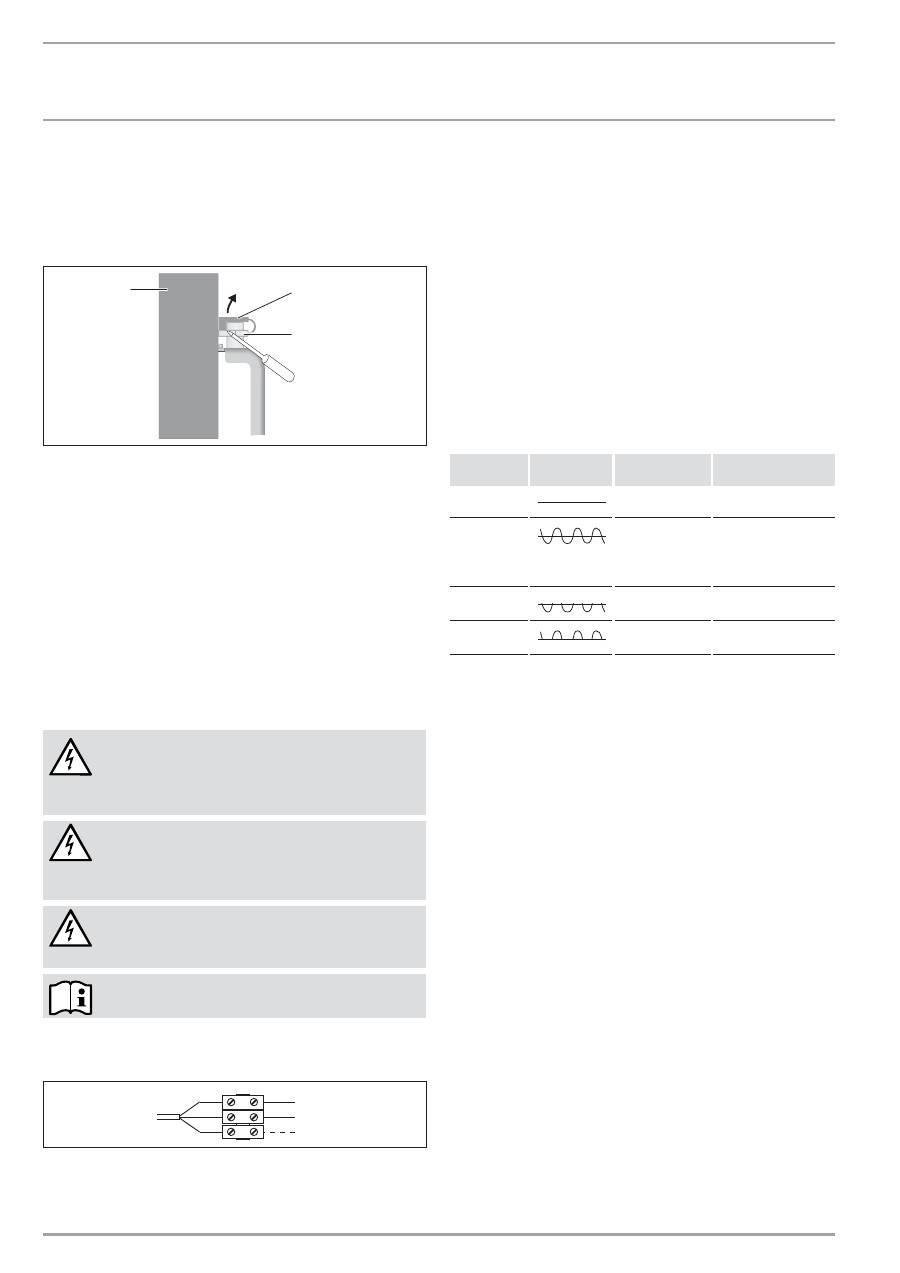
_&166(8(
:::67,(%(/(/7521&20
,167$//$7,21
&200(175(0v',(5$8;'v)$876
1 Appareil
2 Capot de sécurité
3 Goupille de verrouillage
9.3
Dépose de l'appareil
»
Desserrez le capot de sécurité de la goupille de fermeture.
2
6
_0
7
_3
1
_0
1
2
8
1
2
3
1 Appareil
2 Capot de sécurité
3 Goupille de verrouillage
»
Desserrez les goupilles de verrouillage du support mural.
»
Soulevez légèrement l'appareil puis sortez-le par l'avant de son
support mural.
9.4 Raccordement
électrique
»
Veillez à ce que les conduites d’amenée installées sur le site
présentent des sections suffisantes.
»
Veillez à installer une prise de courant ou une prise pour le
raccordement fixe de l’équipement à une distance d’au moins
10 cm sur le côté de l’appareil.
DANGER Électrocution !
Exécutez tous les travaux de raccordement et
d'installation électriques conformément aux
prescriptions.
DANGER Électrocution !
L'appareil doit pouvoir être déconnecté du secteur
par un dispositif de coupure omnipolaire ayant une
ouverture minimale des contacts de 3 mm.
DANGER Électrocution !
Il est interdit d’effectuer une installation avec une
conduite de raccordement posée de manière fixe.
Se référer à la plaque signalétique. La tension indiquée
doit concorder avec celle du secteur.
Série CNS-UE
»
Raccordez le câble à trois brins à une boîte de raccordement
comme indiqué ci-après en cas de raccordement fixe.
1
2
1
2
3
3
2
6
_0
7
_3
1
_0
1
7
5
1 Conducteur neutre = bleu
2 Phase = marron
3 Conducteur de commande = noir
Pour raccorder l’appareil, vous avez les 3 possibilités suivantes :
1 Raccordement de l’appareil sans conducteur de commande
Appareil sans pilotage. Le conducteur de commande n’est pas
raccordé. Isolez dans ce cas le conducteur de commande.
2 Abaissement de la température via le conducteur de
commande
Pour réduire de 3 °C la température réglée au thermostat,
le conducteur de commande noir est activé par un contact
électronique externe, celui d’une minuterie par exemple.
3 Raccordement du conducteur de commande à une unité de
commande
Vous pouvez raccorder l’appareil à toute unité de commande qui
émet les formes de signaux mentionnées dans le tableau suivant
en tant que signal de commande.
2UGUH
2VFLOORVFRSH 0RGHGH
IRQFWLRQQHPHQW
7HPSÒUDWXUHGH
FKDXIIH
Pas de courant
Mode confort
Selon le réglage du
thermostat
Ondulation
complète 230 V
Mode ECO
Abaisser de 3 °C par
rapport au réglage
effectué sur le
thermostat
Alternance
négative - 230 V
Mode protection
hors gel
Température pour mise
hors gel
Alternance
positive + 230 V
Arrêt
Aucune
10. Comment remédier aux défauts
En cas de remplacement, le câble de raccordement au secteur ne
doit être remplacé que par des pièces de rechange dˇorigine et
par un installateur.
11. Remise de l'appareil au client
Expliquez le fonctionnement de l'appareil à l'utilisateur. Attirez
particulièrement son attention sur les consignes de sécurité.
Remettez-lui les instructions d'utilisation et d'installation.
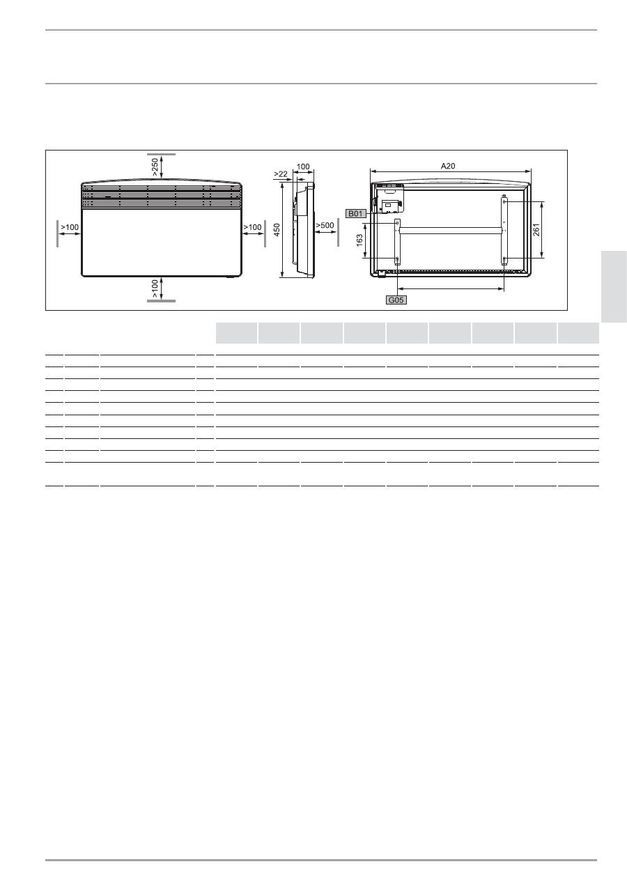
:::67,(%(/(/7521&20
&166(8(_
)5
$1
q$
,6
,167$//$7,21
'211v(67(&+1,48(6
12. Données techniques
12.1 Dimensions variante suspendue au mur
8
0
_0
7
_3
1
_000
9
&16
6(8(
&16
6(8(
&16
6(8(
&16
6(8(
&16
6(8(
&16
6(8(
&16
6(8(
&16
6(8(
&16
6(8(
A10 Appareil Hauteur
mm
450
A20 Appareil Largeur
mm
370
445
445
590
590
740
740
890
1040
A30 Appareil Profondeur
mm
100
A50 Appareil Dégagement min. en haut
mm
250
A51
Appareil Dégagement min. en bas
mm
100
A52 Appareil Dégagement min. à droite
mm
100
A53 Appareil Dégagement min. à gauche mm
100
A54 Appareil Dégagement min. avant
mm
500
A55 Appareil Dégagement min. arrière
mm
22
B01 Passage de câbles électriques
G05 Fixation
murale
Écartement des trous
mm
121
195
195
343
343
491
491
639
787

_&166(8(
:::67,(%(/(/7521&20
,167$//$7,21
'211v(67(&+1,48(6
12.2 Tableau de données CNS-SE
&16
6(
&16
6(
&16
6(
&16
6(
&16
6(
&16
6(
&16
6(
&16
6(
&16
6(
229740
229741
229742
229743
229744
229745
229746
229747
229748
Puissance connectée
kW
0,5
0,75
1,0
1,25
1,5
1,75
2,0
2,5
3,0
Plage de réglage
°C
6-30
6-30
6-30
6-30
6-30
6-30
6-30
6-30
6-30
Position protection antigel
°C
7
7
7
7
7
7
7
7
7
Raccordement électrique
1/N~230 V
1/N~230 V
1/N~230 V
1/N~230 V
1/N~230 V
1/N~230 V
1/N~230 V
1/N~230 V
1/N~230 V
Allures de puissance
Hauteur
mm
450
450
450
450
450
450
450
450
450
Largeur
mm
370
445
445
590
590
740
740
890
1040
Profondeur
mm
100
100
100
100
100
100
100
100
100
Poids
kg
3,8
4,4
4,4
5,7
5,7
6,8
6,8
8,1
9,4
Degré de protection (IP)
IP24
IP24
IP24
IP24
IP24
IP24
IP24
IP24
IP24
Classe de protection
II
II
II
II
II
II
II
II
II
Couleur
blanc neige blanc neige blanc neige blanc neige blanc neige blanc neige blanc neige blanc neige blanc neige
12.3 Tableau de données CNS-UE
&16
8(
&16
8(
&16
8(
&16
8(
&16
8(
&16
8(
&16
8(
&16
8(
&16
8(
229749
229750
229751
229752
229753
229754
229755
229756
229757
Puissance connectée
kW
0,5
0,75
1,0
1,25
1,5
1,75
2,0
2,5
3,0
Plage de réglage
°C
6-30
6-30
6-30
6-30
6-30
6-30
6-30
6-30
6-30
Position protection antigel
°C
7
7
7
7
7
7
7
7
7
Raccordement électrique
1/N~230 V
1/N~230 V
1/N~230 V
1/N~230 V
1/N~230 V
1/N~230 V
1/N~230 V
1/N~230 V
1/N~230 V
Allures de puissance
Hauteur
mm
450
450
450
450
450
450
450
450
450
Largeur
mm
370
445
445
590
590
740
740
890
1040
Profondeur
mm
100
100
100
100
100
100
100
100
100
Poids
kg
3,3
4
4
5,2
5,2
6,3
6,3
7,7
8,9
Degré de protection (IP)
IP24
IP24
IP24
IP24
IP24
IP24
IP24
IP24
IP24
Classe de protection
II
II
II
II
II
II
II
II
II
Couleur
blanc neige blanc neige blanc neige blanc neige blanc neige blanc neige blanc neige blanc neige blanc neige
:::67,(%(/(/7521&20
&166(8(_
)5
$1
q$
,6
,17(51$7,21$/
6(59,&($35u69(17((7*$5$17,((19,5211(0(17(75(&<&/$*(
"!%##
#
#"###
!
!
"#
##
$#
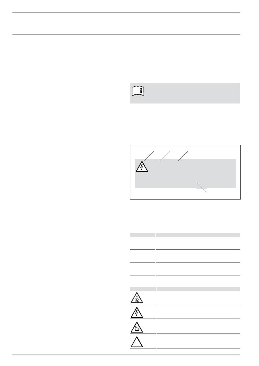
_&166(8(
:::67,(%(/(/7521&20
,1+28'_%(',(1,1*
$/*(0(1(,16758&7,(6
1. Algemene
instructies
1.1
Informatie over dit document
Het hoofdstuk
Bediening
is zowel bedoeld voor de gebruiker als
voor de installateur.
Het hoofdstuk
Installatie
is bestemd voor de installateur.
Lees deze handleiding voor gebruik zorgvuldig door
en bewaar deze op een veilige plaats. Overhandig
de handleiding in voorkomende gevallen aan een
volgende gebruiker.
1.2 Legende
1.2.1 Opbouw
veiligheidsinstructies
De veiligheidsinstructies bestaan uit een waarschuwingssymbool,
een trefwoord en een tekstverwijzing. De veiligheidsinstructies
hebben een grijze achtergrond.
Voorbeeld:
GEVAAR voor elektrische schok
Plaats het toestel op een wijze dat schakel- en
regelinrichtingen niet kunnen worden aangeraakt
door een persoon die in bad zit of onder de
douche staat.
1
2
3
4
1 Symbool (zie hoofdstuk Waarschuwingssymbolen/symbolen)
2 Trefwoord (zie hoofdstuk Trefwoorden)
3 Naam (zie hoofdstuk Waarschuwingssymbolen/symbolen)
4 Instructietekst
1.2.2 Trefwoorden
75():225'
%HWHNHQLV
GEVAAR
Instructies die niet worden opgevolgd, kunnen zwaar letsel
of overlijden veroorzaken. Deze worden aangeduid met het
trefwoord GEVAAR.
WAARSCHUWING
Instructies die niet worden opgevolgd, kunnen zwaar letsel
of overlijden veroorzaken. Deze worden gemarkeerd door
het trefwoord WAARSCHUWING.
OPGELET
Instructies die niet worden opgevolgd, kunnen
middelmatig zwaar of licht letsel veroorzaken. Deze
worden weergegeven met het trefwoord OPGELET.
1.2.3 Waarschuwingssymbolen/symbolen
6\PERRO
1DDP
Letsel
Elektrische schok
Verbranden of verschroeien
!
Andere situaties
BEDIENING _____________________________________________ 30
1. Algemene
instructies
_________________________________________ 30
1.1 Informatie over dit document ___________________________________ 30
1.2 Legende
_____________________________________________________________ 30
2. Veiligheid
______________________________________________________ 31
2.1 Voorgeschreven
gebruik
_________________________________________ 31
2.2 Veiligheidsvoorschriften
_________________________________________ 31
2.3 Keurmerk
____________________________________________________________ 32
3. Toestelomschrijving
__________________________________________ 32
3.1 Typeserie
CNS-SE
__________________________________________________ 32
3.2 Typeserie
CNS-UE
_________________________________________________ 32
4. Bediening
_____________________________________________________ 32
4.1 Het toestel in- en uitschakelen _________________________________ 32
4.2 Beschrijving van het bedieningspaneel _______________________ 32
4.3 Comfort-bedrijf
____________________________________________________ 32
4.4 ECO-bedrijf__________________________________________________________ 32
4.5 Vorstbeveiliging ____________________________________________________ 32
4.6 Automatisch
________________________________________________________ 32
4.7 Thermostaatbegrenzingen
_______________________________________ 33
4.8 Buiten werking stellen ___________________________________________ 33
5. Reiniging,
verzorging en onderhoud _______________________ 33
6.
Wat moet u doen als ... ______________________________________ 33
INSTALLATIE ___________________________________________ 34
7. Veiligheid
______________________________________________________ 34
7.1 Algemene
veiligheidsaanwijzingen
____________________________ 34
7.2 Voorschriften, normen en bepalingen ________________________ 34
8. Toestelomschrijving __________________________________________ 34
8.1 Leveringstoebehoren
_____________________________________________ 34
9. Montage
_______________________________________________________ 34
9.1 Montage van de wandhouder ___________________________________ 34
9.2 Montage van het toestel _________________________________________ 34
9.3 Demontage van het toestel ______________________________________ 35
9.4 Elektrische
aansluitingen
________________________________________ 35
10. Storingen
verhelpen
__________________________________________ 35
11. Overdracht van het toestel __________________________________ 35
12. Technische
gegevens
_________________________________________ 36
12.1 Afmetingen van de aan de wand bevestigde variant _______ 36
12.2 Gegevenstabel CNS SE ____________________________________________ 36
12.3 Gegevenstabel CNS UE ___________________________________________ 36
KLANTENSERVICE EN GARANTIE _____________________ 37
MILIEU EN RECYCLING _________________________________ 37
%(',(1,1*
9(,/,*+(,'
:::67,(%(/(/7521&20
&166(8(_
1(
'(
5/
$1
'6
Brand
Toestel niet afdekken
Het toestel afdanken
1.2.4 Teksttekens en maten in deze documentatie
Lees de tekst naast dit symbool grondig door.
»
Deze tekstgedeelten en het symbool "
»
" geven aan dat u een
handeling moet verrichten. De vereiste handelingen worden
stapsgewijs beschreven.
— Passages met dit "
–
" symbool zijn lijsten.
1.2.5 Instructies voor het toestel
Toestel niet afdekken!
1.2.6 Formaten
De afmetingen in dit document zijn opgegeven in mm.
Afwijkende meeteenheden worden telkens separaat
aangeduid.
2. Veiligheid
2.1 Voorgeschreven
gebruik
Het toestel is bestemd voor het verwarmen van woonruimten.
Elk ander gebruik geldt niet als voorgeschreven gebruik. Het
voorgeschreven gebruik betekent ook de naleving van deze
handleiding. In geval van wijzigingen of aanpassingen aan het
toestel vervalt de garantie!
2.2 Veiligheidsvoorschriften
Gebruik het toestel uitsluitend als het volledig is geïnstalleerd en
als alle veiligheidsinrichtingen zijn aangebracht.
WAARSCHUWING voor brand
Gebruik het toestel niet ...
—
wanneer er door chemicaliën, stof, gassen of
dampen gevaar voor brand of explosies bestaat in
de ruimte met het toestel;
—
in de onmiddellijke omgeving van leidingen of
containers met brandbare of explosieve stoffen;
—
wanneer in de opstelruimte bouw- of
verbouwingswerkzaamheden worden uitgevoerd;
—
wanneer er wordt gewerkt met benzine, sprays,
boenwas en dergelijke. Ventileer de ruimte
voldoende voordat het toestel wordt opgeladen;
—
wanneer de minimumafstanden tot aangrenzende
objectoppervlakken te klein worden, zoals bij
meubels, gordijnen, vitrage en textiel of overig
brandbaar materiaal (voor minimumafstanden, zie
hoofdstuk Technische gegevens);
—
wanneer een toestelmodule is beschadigd, het
toestel is gevallen of er reeds een storing was.
WAARSCHUWING voor letsel
Als kinderen of personen met beperkte lichamelijke,
zintuiglijke of geestelijke vermogens het toestel
moeten bedienen, moet ervoor worden gezorgd dat
dit alleen gebeurt onder toezicht of na degelijke
instructies door een persoon die voor hun veiligheid
verantwoordelijk is.
Houd altijd toezicht op kinderen en zorg ervoor dat ze
nooit met het toestel spelen!
WAARSCHUWING voor brand
Er mogen op het toestel of in de onmiddellijke omgeving
ervan geen brandbare, ontvlambare of warmte-
isolerende voorwerpen of stoffen worden geplaatst,
zoals wasgoed, dekens, tijdschriften, blikken boenwas
of benzine, spuitbussen en dergelijke.
WAARSCHUWING voor verbranding
Als het toestel in bedrijf is, worden de behuizing en de
afgevoerde lucht heet (meer dan 80 °C).
