Stiebel Eltron RTF с 20.12.2004: инструкция
Раздел: Климатическое Оборудование
Тип: Радиатор
Инструкция к Радиатору Stiebel Eltron RTF с 20.12.2004
9035.02
1
2
3
4
RTF
Deutsch
Fußboden-Temperaturregler
Gebrauchs- und Montageanweisung
English
Controller for Under-floor Heating Systems
Operation and installation instructions
Pyccêèé
Ðåãóëÿòîð òåìïåðàòóðû ïîëà
Èíñòðóêöèÿ ïî ýêñïëóàòàöèè è ìîíòàæó
Technik zum Wohlfühlen
185581
5 21 176 01
Die Montage (Elektroinstallation) sowie die Erstinbetriebnahme dieses Gerätes dürfen nur von einem zugelassenen Fachhandwerker ent-
sprechend dieser Anweisung ausgeführt werden.
This appliance must be installed (electrical installation) and commisioned by approved service technicians in accordance with these
instructions.
Ìîíòàæ (ýëåêòðîìîíòàæ), à òàêæå ââîä â ýêñïëóàòàöèþ è òåõíè÷åñêîå îáñëóæèâàíèå äàííîãî ïðèáîðà ðàçðåøàåòñÿ
ïðîèçâîäèòü òîëüêî ñïåöèàëèñòó, èìåþùåìó äîïóñê, â ñîîòâåòñòâèè ñ äàííîé èíñòðóêöèåé.
2
1
2
3
4
8971.02
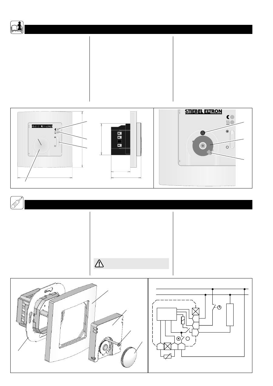
28,5
81,5
85
2
3
44,5
1
1
2
3
4
5
6
7
8972.02
47
4
2
7
8
9
10
8973.02
F
F L
LH
TA
N
Elektronik
RTF
L
N
FT
...
8974.02
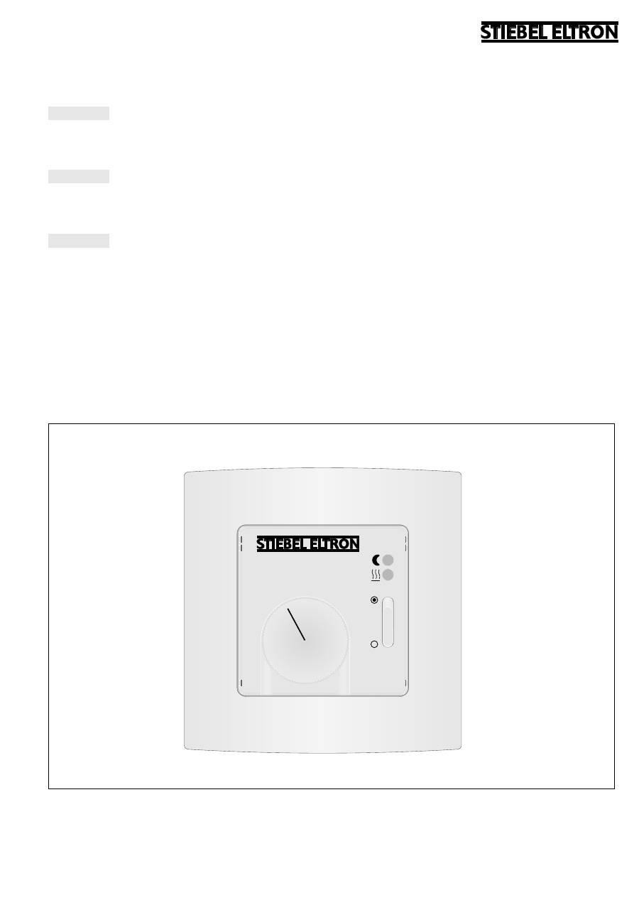
Der Temperaturregler RTF dient zur Regulie-
rung der Wärmeabgabe von Fußbodentem-
perierungen.
1.1 Bedienung
Nach Einschalten der Fußbodentemperierung
über den Schalter (
1
) am RTF und dem Errei-
chen der am Temperaturwählknopf (
2
) ein-
gestellten Temperatur (zwischen ca. 10 und
45 ºC) wird durch intermittierendes Heizen
der gewünschte Temperaturwert gehalten.
Das Aufheizen ist an der leuchtenden roten
LED-Anzeige (
3
) zu erkennen.
Alle elektrischen Anschluss- und Installations-
arbeiten sind nach den VDE-Bestimmungen
(DIN VDE 0100 T520 A3), den Vorschriften
des zuständigen EVU’s sowie den entspre-
chenden nationalen und regionalen Vorschrif-
ten auszuführen.
Installation der Schalterdose in Räumen mit
Badewanne und/oder Dusche
nur außerhalb
der
Schutzbereiche 1 und 2.
Bei Netzausfall bzw. einer Unterbrechung
oder eines Kurzschlusses der Fühlerleitung
wird die Heizung abgeschaltet.
1. Gebrauchsanweisung
für den Benutzer und den Fachmann
2. Montageanweisung
für den Fachmann
Ist eine Zeitschaltuhr an den Regler ange-
schlossen, senkt dieser zur vorgewählten Zeit
den eingestellten Sollwert um ca. 5K ab. Die-
ses ist dann an der leuchtenden grünen LED-
Anzeige (
4
) zu erkennen.
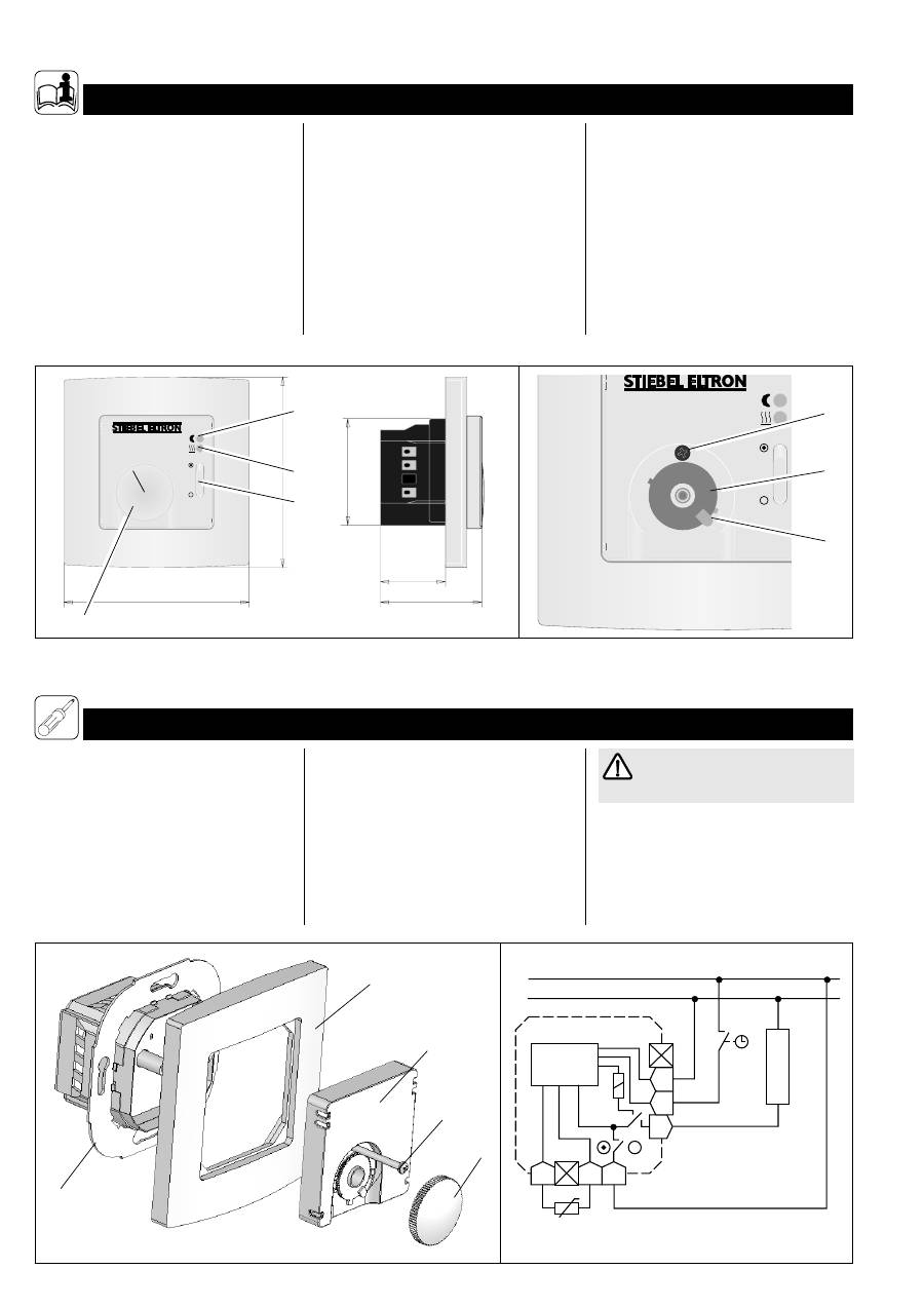
1.2 Temperaturbereich-Be- grenzung
Der Temperatureinstellbereich kann durch
Einengung des Drehwinkels am Tempera-
turwählknopf begrenzt werden. Hierfür ist
wie folgt vorzugehen:
– Temperaturwählknopf (
2
) mit Hilfe eines
Schraubendrehers vom Gehäuse abhebeln;
– Arretierungsstift (
5
) mit Spitzzange vor-
sichtig herausziehen;
– Rasterscheiben (
6
) zur Einstellung der Mi-
nimal- (blau) und/oder Maximaltemperatur
(rot) wie gewünscht verdrehen;
– Arretierungsstift wieder einsetzen;
– Temperaturwählknopf wieder aufsetzen.
2.1 Montage Temperaturfühler
Der Temperaturfühler ist
vor
dem Aufbringen
des Fußboden-Oberbelages in einem Leer-
rohr oberflächenbündig im Untergrund (z. B.
Estrich) zu versenken; vgl. Gebrauchs- und
Montageanweisung Temperiermatte.
Die Anschlussleitung des Fühlers kann mit
einen flexiblen Leiter bis 50 m verlängert
werden.
Im Fehlerfall kann Netzspannung an
der Fühlerleitung liegen!
2.2 Montage Temperaturregler
Der Temperaturregler ist in eine handelsüb-
liche UP-Schalterdosen für Geräte-Ø 55 mm
einzubauen.
Dabei kann der Regler als separat sitzendes
Gerät oder mittels Zwischenrahmen in ver-
schiedene Flächenschaltersysteme integrier-
tes Gerät installiert werden.
Zum Einsetzen des Temperaturreglers ist wie
folgt vorzugehen:
– Temperaturwählknopf (
2
) mit Hilfsmittel,
z.B. einem Schraubendreher, vom Gehäuse
abhebeln;
3
Deutsch
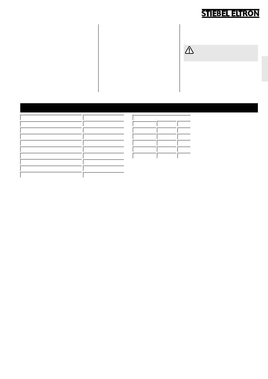
Schutzklasse
ΙΙ
, gemäß dieser Anweisung
Typ
RTF
Schaltleistung
~ 12(2) A 230 V
Einstellbereich
ca. 10 ºC . . . 45 ºC
Temperaturabsenkung (auf Wunsch)
5 K
Schaltdifferenz
1 K
H x B x T
81,5 x 81,5 x 44,5 mm
Schutzart
IP 20
Länge Temperaturfühler (DIN 44574)
4 m
Approbationen
siehe Geräteaufdruck
Fühlerkennwerte
Temperatur
R [kOhm] U [V]
20 °C
2,43
2,22
10 °C
3,66
2,49
40 °C
1,15
1,63
30 °C
1,65
1,92
50 °C
0,82
1,35
– Befestigungsschraube (
7
) entfernen,
Gehäusedeckel (
8
) und Schalterrahmen
(
9
) abnehmen;
– Elektrischen Anschluss nach dem in dieser
Anweisung abgebildetem Schaltbild vor-
nehmen;
– Temperaturregler (
10
) in Schalterdose ein-
setzen und mit dieser verschrauben;
– Gehäusedeckel und Schalterrahmen
wieder aufsetzen und festschrauben;
– Temperaturwählknopf wieder aufsetzen.
Montage- und Gebrauchsanweisung
der Fußbodentemperierung, an die
der Temperaturregler angeschlossen wer-
den soll, ist zu beachten.
2.3 Temperaturabsenkung
Mittels einer an die Klemme TA des Tempera-
turreglers angeschlossen externen Schaltuhr
oder eines Schalters ist eine Temperaturab-
senkung um 5 K unterhalb des am Regler ein-
gestellten Wertes möglich.
3. Technische Daten
4
1
2
3
4
8971.01
28,5
81,5
81,5
2
3
44,5
1
1
2
3
4
5
6
7
8972.02
47
4
2
7
8
9
10
8973.01
F
F L
LH
TA
N
Elektronik
RTF
L
N
FT
...
8974.02
The RTF controls the heat output of your
under-floor heating system.
1.1 Operation
After switching on the under-floor heating
with the on/off switch (
1
) on the RTF and
setting the temperature with the temperature
selection knob (
2
), the floor will heat up and
stay at the set temperature.
During the heating times the red LED light
(
3
) will illuminate.
All electrical connections and installation
work must be carried out by a competent
person in accordance with these instructions
and I.E.E. Regulations.
If installed in a bathroom or shower room
the controller must be located outside of
protection zones 1 and 2.
If the sensor probe is damaged, short-
circuited or not connected, the heating
system will be switched off.
1. Operation instructions
for the user and the professional
If a separate time-switch is installed in
conjunction with the RTF, the green set-back
light (
4
), will illuminate during the off periods
and set the temperature to approx. 5 K
below the selected temperature.
1.2 Temperature range limiting
The range of temperatures that can be
chosen can be restricted by using the limiters
located beneath the temperature selection
knob. To do this, take the following actions:
– Carefully remove the temperature selection
knob (
2
) with the help of a screwdriver.
– Remove the locking pin (
5
) by pulling it out.
– Slide the red (maximum) and / or blue
(minimum) plastic disks (
6
) to the
appropriate position e.g. Red – 3 and Blue
– 2.
– Replace the locking pin
– Replace the temperature selection knob,
ensuring that the black line is within the
chosen limits before finally pressing into
position.
2.1 Installing the temperature sensor
The end of the floor temperature sensor
probe must be sited in the floor, within the
area of the heating mat. It is recommended
that the sensor and cable are sited within a
piece of trunking or conduit ( See the Ope-
rating and Installation Instructions for the
Heating Mats). The sensor cable can be
extended to up to 50 metres if required.
In the case of a fault live electricity
can be present in the controller or
sensor lead.
2.2 Installing the Controller
The controller is designed to be fitted into a
flush back box with an opening of at least
Ø55 mm.
The controller may be installed separately or
in a group of flat-switches by using the
2. Installation instructions
for the professional
5
English
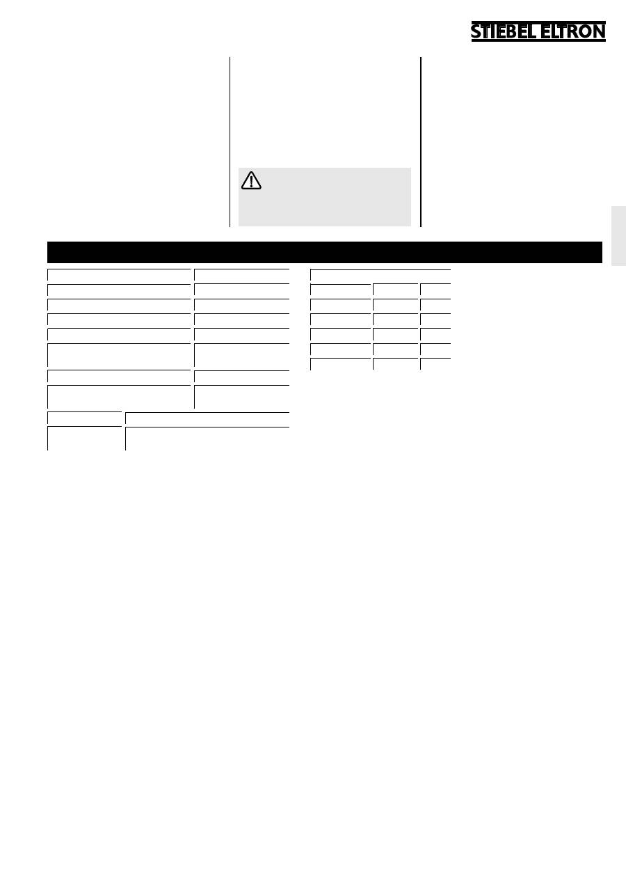
Type
RTF
Switching Capacity
~ 12(2) A 230 V
Range
ca. 10 ºC . . . 45 ºC
Set-back (if required)
5 K
Switching Differential
1 K
H x W x D
81,5 x 81,5 x 44,5 mm
Class
ΙΙ
, acc. this manual
Protection rating
IP 20
Sensor cable length (DIN 44574)
4 m
Approvals
see print on unit
Sensor Values
Temperature R [kOhm] U [V]
20 °C
2,43
2,22
10 °C
3,66
2,49
40 °C
1,15
1,63
30 °C
1,65
1,92
50 °C
0,82
1,35
various frames which belong to the
controller.
To install the controller take the following
steps:
– Carefully remove the temperature
selection knob (
2
) with the help of a
screwdriver.
– Remove the locating screw (
7
) and
remove the cover (
8
) and frame (
9
).
– Connect the electrical connections in
accordance with the wiring diagram below
and as follows:
t
The sensor probes are connected to
the 2 terminals marked ‘F’.
t
The incoming mains electricity
connection should be connected as
follows;
y
Live to ‘L’
y
Neutral to ‘N’
y
Earth to Earth terminal on the back
box.
t
The heating mats connections should be
as follows;
y
Live to ‘LH’
y
Neutral to ‘N’ (common with the
incoming mains supply)
y
Earth to Earth terminal on the back
box
– Fit the controller (
10
) into the back box
using the locating screw holes on the back
plate.
– Refit the frame (
9
) and cover (
8
).
The Instructions for the controller
and the under-floor heating should
be kept together.
2.3 Set-back Temperature
By using the terminal TA in conjunction with
an external time-switch or a switch, a set-
back facility, reducing the set temperature by
5K is possible.
3. Technical data

6
1
2
3
4
8971.02
28,5
81,5
85
2
3
44,5
1
1
2
3
4
5
6
7
8972.02
47
4
2
7
8
9
10
8973.02
F
F L
LH
TA
N
Elektronik
RTF
L
N
FT
...
8974.02
Ðåãóëÿòîð òåìïåðàòóðû RTF ñëóæèò äëÿ
ðåãóëèðîâêè òåìïåðàòóðû ïîëà ñ
óñòàíàâëèâàåìûì òåìïåðàòóðíûì
ðåæèìîì.
1.1 Îáñëóæèâàíèå
Ïîñëå âêëþ÷åíèÿ ïîäîãðåâà ïîëîâ ñ
ïîìîùüþ âûêëþ÷àòåëÿ (
1
) íà
ðåãéóëÿòîðå è äîñòèæåíèÿ òåìïåðàòóðû,
óñòàíîâëåííîé ïîñðåäñòâîì ðó÷êè
âûáîðà òåìïåðàòóðû (
2
) (ìåæäó 10 è
45°Ñ), â õîäå ïåðèîäè÷åñêîãî
ïîäîãðåâà ïîääåðæèâàåòñÿ æåëàåìîå
çíà÷åíèå òåìïåðàòóðû. Ïðîöåññ
1. Èíñòðóêöèÿ ïî ýêñïëóàòàöèè
äëÿ ñïåöèàëèñòà è ïîëüçîâàòåëÿ
ïîäîãðåâà ìîæíî îïðåäåëèòü ïî
ñâåòÿùåìóñÿ èíäèêàòîðó (
3
). Åñëè ê
ðåãóëÿòîðó ïîäêëþ÷åí òàéìåð, òî â
çàäàííûé èíòåðâàë âðåìåíè
óñòàíîâëåííîå çíà÷åíèå òåìïåðàòóðû
ïîíèæàåòñÿ ïðèìåðíî íà 5Ê. Ýòî
ìîæíî îïðåäåëèòü ïî ñâåòÿùåìóñÿ
çåëåíîìó èíäèêàòîðó (
4
).
1.2 Îãðàíè÷åíèå òåìïåðàòóðíîãî äèàïàçîíà
Äèàïàçîí óñòàíîâêè òåìïåðàòóðû
ìîæíî îãðàíè÷èòü ïóòåì óìåíüøåíèÿ
óãëà ïîâîðîòà ðó÷êè âûáîðà
òåìïåðàòóðû. Äëÿ ýòîãî íåîáõîäèìî
âûïîëíèòü ñëåäóþùèå øàãè:
– ñíÿòü ðó÷êó âûáîðà òåìïåðàòóðû (
2
)
ïðè ïîìîùè îòâåðòêè;
– îñòîðîæíî èçâëå÷ü ñòîïîðíûé
ôèêñàòîð (
5
) ñ ïîìîùüþ èíñòðóìåíòà;
– óñòàíîâèòü øàéáû (
6
) äëÿ íàñòðîéêè
ìèíèìàëüíîé (ãîëóáîé öâåò) è/èëè
ìàêñèìàëüíîé òåìïåðàòóðû
(êðàñíûé öâåò);
– óñòàíîâèòü ñòîïîðíûé ôèêñàòîð íà
ìåñòî;
– óñòàíîâèòü ðó÷êó âûáîðà
òåìïåðàòóðû íà ìåñòî.
2. Èíñòðóêöèÿ ïî ìîíòàæó
äëÿ ñïåöèàëèñòà
Âñå ðàáîòû ïî ýëåêòðè÷åñêîìó
ïîäêëþ÷åíèþ è óñòàíîâêå ñëåäóåò
ïðîâîäèòü ñîãëàñíî îïðåäåëåíèÿì
Ñîþçà íåìåöêèõ ýëåêòðîòåõíèêîâ
(DIN VDE 0100 T520 A3), ïðàâèëàì
ýëåêòðîñíàáæàþùåãî ïðåäïðèÿòèÿ, à
òàêæå íàöèîíàëüíûì è ðåãèîíàëüíûì
ïðàâèëàì.
Óñòàíîâêà êîðîáêè äëÿ âûêëþ÷àòåëÿ â
ïîìåùåíèÿõ ñ âàííîé è/èëè äóøåì
çàïðåùåíà â çîíàõ áåçîïàñíîñòè 1 è 2!
Ïðè ðàçðûâå èëè êîðîòêîì çàìûêàíèè
ïðîâîäà òåìïåðàòóðíîãî äàò÷èêà
íàãðåâ îòêëþ÷àåòñÿ.
2.1 Ìîíòàæ òåìïåðàòóðíîãî äàò÷èêà
Ïåðåä íàíåñåíèåì âåðõíåãî ñëîÿ
ïîëîâîãî ïîêðûòèÿ íåîáõîäèìî
óëîæèòü ïîëóþ òðóáêó äëÿ
òåìïåðàòóðíîãî äàò÷èêà â îñíîâó òàêèì
îáðàçîì, ÷òîáû ïîâåðõíîñòü îñíîâû
îñòàëàñü ïëîñêîé; ñì. èíñòðóêöèþ ïî
ýêñïëóàòàöèè è ìîíòàæó äëÿ
íàãðåâàòåëüíûõ ìàòîâ.
Ñ ïîìîùüþ ãèáêîãî ïðîâîäà
ñòàíäàðòíûé ïðîâîä òåìïåðàòóðíîãî
äàò÷èêà ìîæíî óäëèíèòü äî 50 ì.
Ïðè ïîâðåæäåíèè ðåãóëÿòîðà
ïðîâîä òåìïåðàòóðíîãî äàò÷èêà
ìîæåò îêàçàòüñÿ ïîä ñåòåâûì
íàïðÿæåíèåì.
2.2 Ìîíòàæ ðåãóëÿòîðà òåìïåðàòóðû
Ðåãóëÿòîð òåìïåðàòóðû íåîáõîäèìî
óñòàíàâëèâàòü â ñòàíäàðòíîé UP-êîðîáêå
äëÿ âûêëþ÷àòåëÿ äèàìåòðîì 55 ìì.
Ïðè ýòîì ðåãóëÿòîð ìîæåò áûòü
óñòàíîâëåí êàê îòäåëüíûé ïðèáîð èëè ñ
7
Pyccêèé
Ñåðòèôèêàòû
ñì. çàâîäñêóþ òàáëè÷êó ñ óêàçàíèåì
íîìèíàëüíûõ äàííûõ
Êëàññ çàùèòû
ΙΙ
,
ñîãëàñíî äàííîé èíñòðóêöèè
Ïîíèæåíèå òåìïåðàòóðû
(âíåøíèé òàéìåð)
5 K
ïîìîùüþ ïðîìåæóòî÷íîé ðàìêè ìîæåò
áûòü èíòåãðèðîâàí â ðàçëè÷íûå
ñèñòåìû íàïîëüíûõ âûêëþ÷àòåëåé.
Äëÿ óñòàíîâêè ðåãóëÿòîðà òåìïåðàòóðû
íåîáõîäèìî âûïîëíèòü ñëåäóþùèå
äåéñòâèÿ:
– ñíÿòü ðó÷êó âûáîðà òåìïåðàòóðû (
2
)
ïðè ïîìîùè îòâåðòêè;
– âûêðóòèòü âèíò (
7
) è ñíÿòü êðûøêó
êîðïóñà (
8
) è ðàìêó ïåðåêëþ÷àòåëÿ
(
9
);
– ïðîèçâåñòè ýëåêòðè÷åñêîå
ïîäêëþ÷åíèå ñîãëàñíî ñõåìå,
ïðèâåäåííîé â äàííîé èíñòðóêöèè;
– óñòàíîâèòü ðåãóëÿòîð òåìïåðàòóðû â
êîðîáêó äëÿ ïåðåêëþ÷àòåëÿ è
çàôèêñèðîâàòü âèíòîâûì
ñîåäèíåíèåì;
– óñòàíîâèòü êðûøêó êîðïóñà,
ïðîìåæóòî÷íóþ ðàìêó è ðàìêó
ïåðåêëþ÷àòåëÿ â îáðàòíîì ïîðÿäêå è
çàêðåïèòü âèíòîì (
7
);
– óñòàíîâèòü ðó÷êó âûáîðà
òåìïåðàòóðû íà ìåñòî.
Íåîáõîäèìî ó÷èòûâàòü
òðåáîâàíèÿ èíñòðóêöèè ïî
ýêñïëóàòàöèè äëÿ íàãðåâàòåëüíûõ
ìàòîâ, ê êîòîðûì äîëæåí áûòü
ïîäêëþ÷åí ðåãóëÿòîð òåìïåðàòóðû.
2.3 Ïîíèæåíèå òåìïåðàòóðû
Ñ ïîìîùüþ âíåøíåãî òàéìåðà,
ïîäêëþ÷åííîãî ê êëåììå ÒÀ ðåãóëÿòîðà
òåìïåðàòóðû âîçìîæíî ïîíèæåíèå
òåìïåðàòóðû íà 5Ê íèæå çíà÷åíèÿ,
íàñòðîåííîãî íà ðåãóëÿòîðå.
3. Òåõíè÷åñêèå õàðàêòåðèñòèêè
Òèï
RTF
Êîììóòàöèîííàÿ ìîùíîñòü
~ 12(2) A 230 V
Äèàïàçîí íàñòðîéêè
îêîëî
10
º
C . . . 45
º
C
Ïåðåïàä òåìïåðàòóðû
1 K
Âûñîòà õ øèðèíà õ ãëóáèíà
81,5 x 81,5 x 44,5 mm
Âèä çàùèòû
IP 20
Äëèíà ïðîâîäà òåìïåðàòóðíîãî
äàò÷èêà (DIN 44574)
4 m
Ïàðàìåòðû äàò÷èêà
Òåìïåðàòóðà
R [kOhm] U [V]
20 °C
2,43
2,22
10 °C
3,66
2,49
40 °C
1,15
1,63
30 °C
1,65
1,92
50 °C
0,82
1,35
OSKO-Service Moskau:
129090 Ðîññèÿ, ã. Ìîñêâà, óë. Òðîèöêàÿ, ä.9, ê.1
òåë.: +7 (095) 933-8774 ôàêñ: +7 (095) 933-8775
OSKO-Service St.-Petersburg:
197022 Ðîññèÿ, ã. Ñ.-Ïåòåðáóðã, Êàìåííîîñòðîâñêèé ïð., ä. 50
òåë.: +7 (812) 234-9369, 327-5252 ôàêñ: +7 (812) 325-1346
CAP 185581/33800/3/7977 · ALRE · Änderungen vorbehalten · These instructions are subject to alteration notice! ·
Âîçìîæíû èæìåíåíèÿ
Gedruckt auf
100% Recycling-Papier.
Aktiv im Umweltschutz.
7938
Stiebel Eltron Vertriebszentren
Dortmund
Oespel (Indupark)
Brennaborstr. 19
44149 Dortmund
Telefon
02 31 / 96 50 22-10
E-Mail: dortmund@stiebel-eltron.com
Frankfurt
Rudolf-Diesel-Str. 18
65760 Eschborn
Telefon
0 61 73 / 6 02-10
E-Mail: frankfurt@stiebel-eltron.com
Hamburg
Georg-Heyken-Straße 4a 21147 Hamburg
Telefon
0 40 / 75 20 18-10
E-Mail: hamburg@stiebel-eltron.com
Holzminden/Info-Center
Berlin/Hannover/Nürnberg
Dr.Stiebel-Straße
37603 Holzminden
Telefon
0 180 3 / 70 20 10
E-Mail: info-center@stiebel-eltron.com
Köln
Ossendorf (Butzweiler Hof)
Mathias-Brüggen-Str. 132 50829 Köln
Telefon
02 21 / 5 97 71-10
E-Mail: koeln@stiebel-eltron.com
Leipzig
Airport Gewerbepark/Glesien
Ikarusstr. 10
04435 Schkeuditz-Glesien
Telefon
03 42 07 / 7 55-10
E-Mail: leipzig@stiebel-eltron.com
München
Hainbuchenring 4
82061 Neuried
Telefon
0 89 / 89 91 56-10
E-Mail: muenchen@stiebel-eltron.com
Stuttgart
Weilimdorf
Motorstr. 39
70499 Stuttgart
Telefon
07 11 / 9 88 67-10
E-Mail: stuttgart@stiebel-eltron.com
Adressen und Kontakte www.stiebel-eltron.com
Zentrale Holzminden
Stiebel Eltron GmbH & Co. KG
Dr.-Stiebel-Str.
37603 Holzminden
Telefon
0 55 31 / 7 02-0
Fax Zentrale
0 55 31 / 7 02-4 80
info@stiebel-eltron.com
Internet
www.stiebel-eltron.com
Stiebel Eltron International GmbH
Dr.-Stiebel-Str.
37603 Holzminden
Telefon
0 55 31 / 7 02-0
Fax
0 55 31 / 7 02-4 79
info@stiebel-eltron.com
Internet
www.stiebel-eltron.com
Tochtergesellschaften und Vertriebs-
zentren Europa und Übersee
Belgique
Stiebel Eltron Sprl / Pvba
Rue Mitoyenne 897
B-4840 Welkenraedt
087-88 14 65
Fax 087-88 15 97
stiebel@skynet.be
Internet
www.stiebel-eltron.com
C
∨∨∨∨∨
eská republika
Stiebel Eltron spol. s r.o.
K Háju
o
oo
oo
m 946
C
∨∨∨∨∨
Z-15500 Praha 5-Stodulky
2-511 16 111
Fax 2-355 12 122
info@stiebel-eltron.cz
Internet
www.stiebel-eltron.cz
France
Stiebel Eltron S.A.S.
7-9, rue des Selliers
B.P. 85107
F-57073 Metz-Cédex
03-87-74 38 88
Fax 03-87-74 68 26
secretcom@stiebel-eltron.fr
Internet
www.stiebel-eltron.fr
Great Britain
Stiebel Eltron Ltd.
Lyveden Road
Brackmills
GB-Northampton NN4 7ED
016 04-76 64 21
Fax 016 04-76 52 83
info@stiebel-eltron.co.uk
Internet
www.stiebel-eltron.co.uk
Magyarország
Stiebel Eltron Kft.
Pacsirtamezo´´
u.
41
H-1036 Budapest
012 50-60 55
Fax 013 68-80 97
info@stiebel-eltron.hu
Internet
www.stiebel-eltron.hu
Nederland
Stiebel Eltron Nederland B.V.
Daviottenweg 36
Postbus 2020
NL-5202 CA's-Hertogenbosch
073-6 23 00 00
Fax 073-6 23 11 41
stiebel@stiebel-eltron.nl
Internet
www.stiebel-eltron.nl
Österreich
Stiebel Eltron Ges.m.b.H.
Eferdinger Str. 73
A-4600 Wels
072 42-4 73 67-0
Fax 072 42-4 73 67-42
info@stiebel-eltron.at
Internet
www.stiebel-eltron.at
Polska
Stiebel Eltron sp.z. o.o
ul. Instalatorów 9
PL-02-237 Warszawa
022-8 46 48 20
Fax 022-8 46 67 03
stiebel@stiebel-eltron.com.pl
Internet
www.stiebel-eltron.com.pl
Sverige
Stiebel Eltron AB
Box 206
SE-641 22 Katrineholm
0150-48 7900
Fax 0150-48 7901
info@stiebel-eltron.se
Internet
www.stiebel-eltron.se
Schweiz
Stiebel Eltron AG
Netzibodenstr. 23 c
CH-4133 Pratteln
061-8 16 93 33
Fax 061-8 16 93 44
info@stiebel-eltron.ch
Internet
www.stiebel-eltron.com
Thailand
Stiebel Eltron Ltd.
469 Building 77, Bond Street
Tambon Bangpood
Ampur Pakkred
Nonthaburi 11120
02-960 1602-4
Fax 02-960 1605
stiebel@loxinfo.co.th
Internet
www.stiebeleltronasia.com
USA
Stiebel Eltron Inc.
242 Suffolk Street
Holyoke MA 01040
04 13-5 38-78 50
Fax 04 13-5 38-85 55
info@stiebel-eltron-usa.com
Internet
www.stiebel-eltron-usa.com
Unseren zentralen Service erreichen Sie unter 0 180 3...
... in der Zeit von:
Montag bis Donnerstag 7
15
bis 18
00
Uhr
Freitag
7
15
bis 17
00
Uhr
Info-Center
allgemeine Information
und technische Auskunft
Telefon 0 180 3 - 70 20 10
Telefax
0 180 3 / 70 20 15
E-Mail: info-center@stiebel-eltron.com
Kundendienst Telefon 0 180 3 - 70 20 20
Telefax
0 180 3 / 70 20 25
E-Mail: kundendienst@stiebel-eltron.com
Ersatzteil-Verkauf Telefon 0 180 3 - 70 20 30
Telefax
0 180 3 / 70 20 35
E-Mail: ersatzteile@stiebel-eltron.com
0,09 /min (Stand: 3/04)
Technik zum Wohlfühlen
