Stiebel Eltron SBP E с 12.04.2008: installation
installation: Stiebel Eltron SBP E с 12.04.2008
16
| sBp 1000-1500 e | e sol | e cool
www.stiebel-eltron.com
installation
safety
installation
6. safety
Only a qualified contractor should carry out installation, commis-
sioning, maintenance and repair of the appliance.
6.1 general safety instructions
We can only guarantee trouble-free function and operational reli-
ability if original spare parts intended for the appliance are used.
6.2 regulations, standards and instructions
Note
Observe all applicable national and regional regulations
and instructions.
7. appliance description
7.1 standard delivery
Delivered with the appliance:
- Dummy flange
- additional type plate
7.2 accessories
7.2.1 required accessories
Depending on the static pressure, safety assemblies and pressure
reducing valves are available. These type-tested safety assemblies
protect the appliance against unacceptable excess pressure.
7.2.2 Further accessories
In addition, heat exchangers, flanged and threaded immersion
heaters and thermal insulation are available as accessories.
If it is not possible to insert a rod anode from above, install a
segmented anode.
8. Preparations
8.1 installation site
f
f
Always install the appliance in a room free from the risk of
frost and near the draw-off point.
f
f
Ensure the floor has sufficient load bearing capacity and
evenness (see chapter “Specification / Data table”).
f
f
Observe the room height and height when tilted (see chapter
“Specification / Data table”).
8.2 transport
Use the lifting eyes at the top of the appliance to assist handling.
9. Preparing for installation
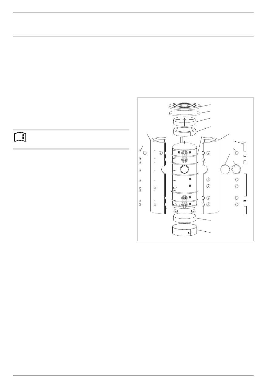
9.1 Fitting the thermal insulation, if appropriate
f
f
Position the appliance in its intended site.
f
f
Fit the thermal insulation according to the instructions sup-
plied. For this, ensure that there is enough space for the
installation task. You can then link the appliance into the
heating system.
26
�0
3�
01
�0
95
5
1
2
3
11
4
5
12
6
7
8
9
10
14
13
1 Cover
2 Top thermal insulation section
3 Top thermal insulation section
4 Top thermal insulation ring
5 Convection brake
6 R.h. thermal insulation section
7 Cover strip
8 Connection cover (including insulation)
9 Thermal insulation, flange
10 Flange cover
11 Thermal insulation section, bottom
12 Thermal insulation ring, bottom
13 Rose
14 Left thermal insulation section
www.stiebel-eltron.com
sBp 1000-1500 e | e sol | e cool |
17
EN
G
LI
SH
installation
preparing for installation
f
f
On cylinders supplied horizontally, insert the bottom thermal
insulation section inside the support ring, prior to position-
ing the cylinder. Slightly tip the vertically delivered cylinder
in order to position the bottom thermal insulation section.
f
f
Surround the support ring with the bottom thermal insula-
tion ring and secure it with adhesive tape.
f
f
Remove the foil from the 5 foam strips (convection brakes)
and stick them around the cylinder in the positions shown.
f
f
Prior to fitting them, shape the right hand and left hand ther-
mal insulation sections into a semi-circular form for approx.
10 seconds. A pressure-activated adhesive then holds the
thermal insulation sections in the required shape and makes
fitting them easier.
Please note that the use of tensioning straps may damage the
thermal insulation.
f
f
Push the thermal insulation sections over the connections on
the appliance.
f
f
Connect the thermal insulation sections at the front by clip-
ping the hook closure strip into the last hook strip. If neces-
sary, the short black cover strips can be used to temporarily
hold the hook closure strips together.
f
f
Position the thermal insulation sections around the cylinder
and connect the thermal insulation sections at the back by
clipping the hook closure strip into the first or second hook
strip.
f
f
Adjust the thermal insulation sections on the appliance by
patting and pressing them down with the palm of the hand.
f
f
Starting from the top, retighten the hook closure strip from
the top until it hooks into the final hook strip.
f
f
Place the thermal insulation ring and the two thermal insula-
tion sections on the top.
f
f
Place the cover over the thermal insulation sections.
f
f
Fit the cover strips onto the hook closure strips. If required,
the cover strips can be trimmed to size.
f
f
Fill the hollow spaces near the connections with the soft
foam inserts.
f
f
Push the roses and caps into the apertures.
Note
Affix the additional type plate in a clearly visible position
on the thermal insulation.
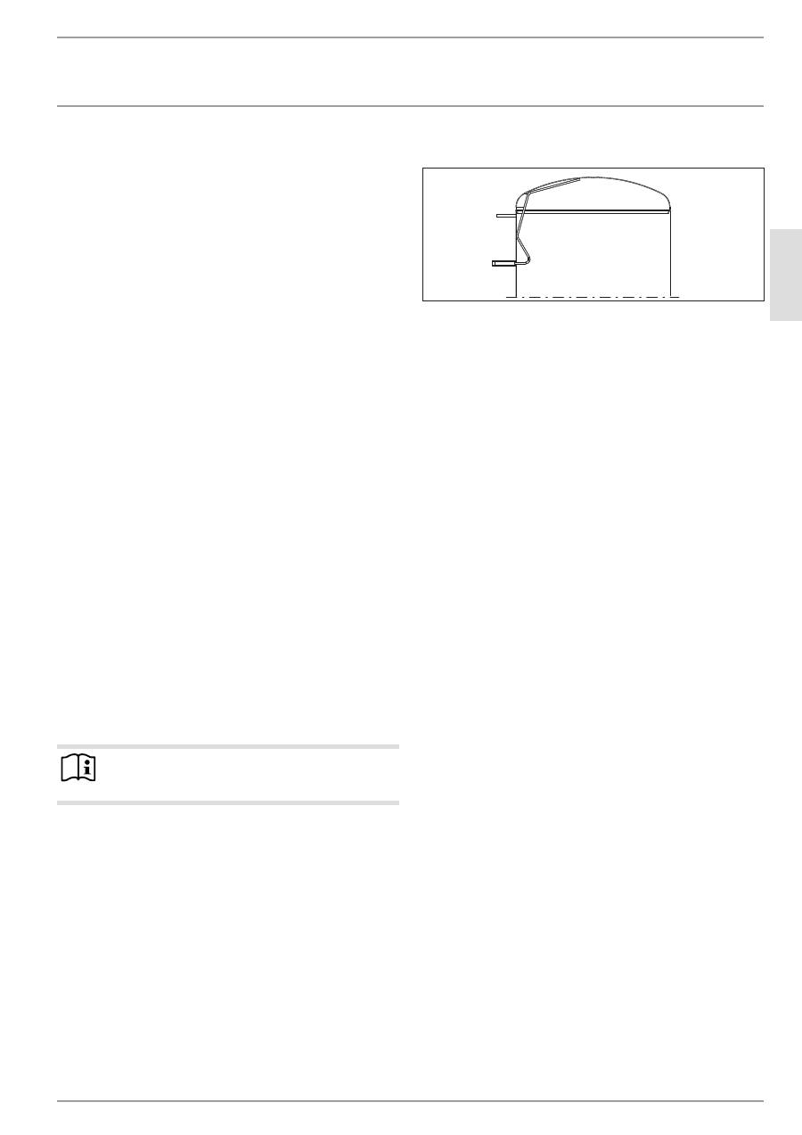
9.2 installing the manual air vent valve
26
�0
3�
01
�0
97
3
f
f
Install a manual air vent valve at the air vent valve
connection.
9.3 Fitting the temperature sensor
f
f
Fill the protective pipe with heat conducting paste.
f
f
Insert the sensor into the protective pipe until it bottoms.
Prior to inserting contact sensor AVF 6 into the protective pipe,
bend the bias spring forward.
9.4 where appropriate, fit the flanged or threaded
immersion heater.
f
f
Remove the dummy flanges and plugs in order to mount
the heat exchanger, flanged or threaded immersion heater.
Maintain the DC separation towards the cylinder.
18
| sBp 1000-1500 e | e sol | e cool
www.stiebel-eltron.com
installation
Commissioning
10. commissioning
10.1 commissioning
!
Material losses
A safety valve is required.
f
f
Open a draw-off point until the appliance has filled up and
the pipework is free of air.
f
f
Adjust the flow rate. For this, observe the maximum permis-
sible flow rate with a fully opened tap (see chapter “Specifi-
cation / Data table”). If necessary reduce the flow rate at the
butterfly valve of the safety assembly.
f
f
Carry out a tightness check.
f
f
Vent the internal indirect coil.
f
f
Switch the mains power ON if required.
f
f
Check the function of the safety assembly.
f
f
Check the function of fitted accessories.
f
f
Then check the function of the solar thermal system, if
appropriate.
f
f
If relevant, check that the DHW temperature displayed on the
heat source control unit is correct.
10.1.1 appliance handover
f
f
Explain the appliance function to users and familiarise them
with its operation.
f
f
Make users aware of potential dangers, especially the risk of
scalding.
f
f
Hand over these instructions.
10.2 recommissioning
See chapter “Commissioning”.
11. shutting down
f
f
If necessary, disconnect any accessories installed from the
mains at the MCB/fuse in the fuse box.
f
f
Drain the appliance. See chapter “Maintenance / Draining the
appliance”.
12. maintenance
No special maintenance is required for the appliance. A regular
visual check is sufficient.
12.1 draining the appliance
WARNING Burns
Hot water may escape during the draining process.
If the appliance needs to be drained for maintenance or to protect
the whole installation when there is a risk of frost, proceed as
follows:
f
f
Close the shut-off valve in the cold water inlet pipe.
f
f
Open the hot water taps on all draw-off points.
f
f
For draining the appliance, remove the thermal insulation
around the drain connector.
www.stiebel-eltron.com
sBp 1000-1500 e | e sol | e cool |
19
EN
G
LI
SH
installation
specification
13. specification
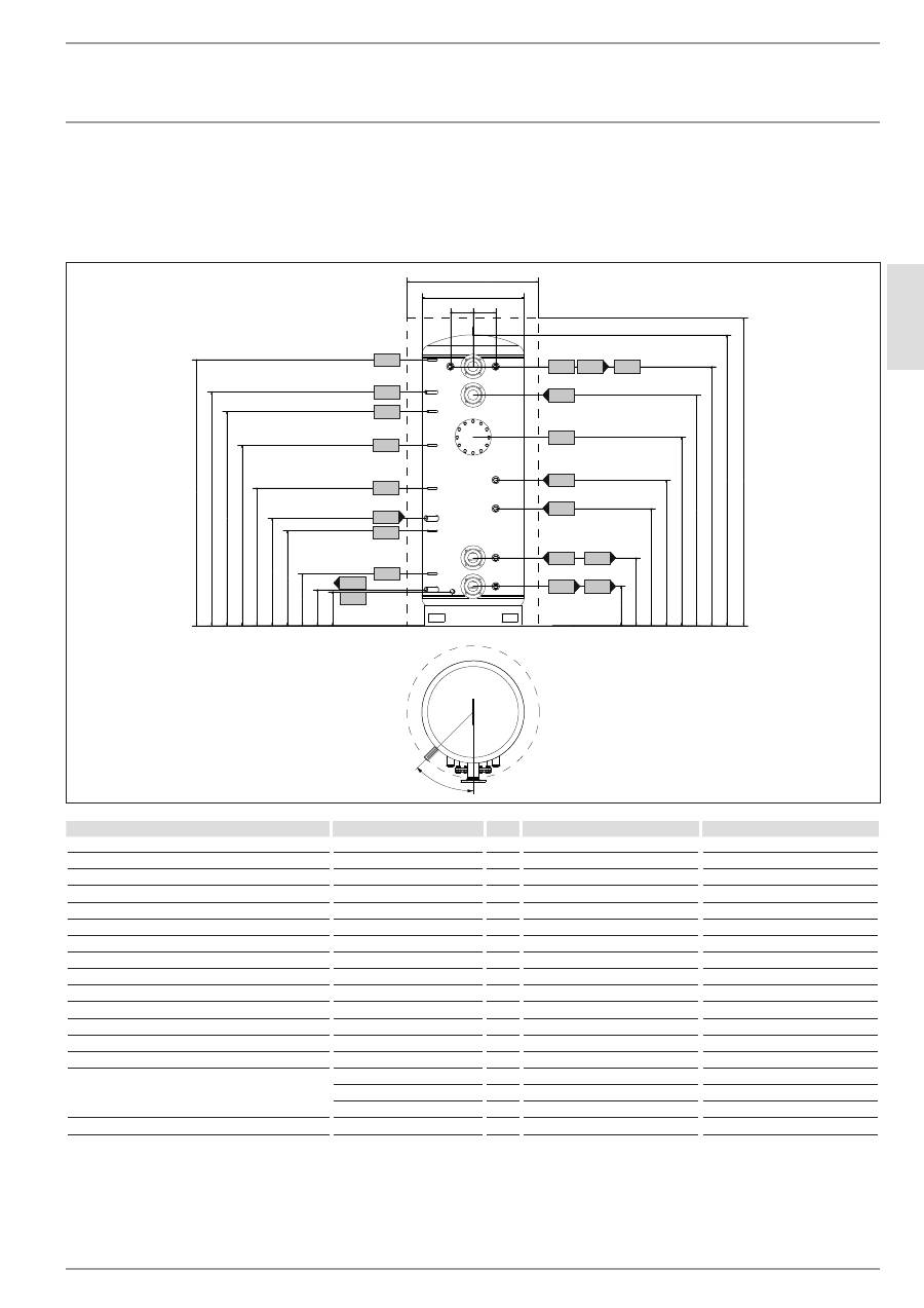
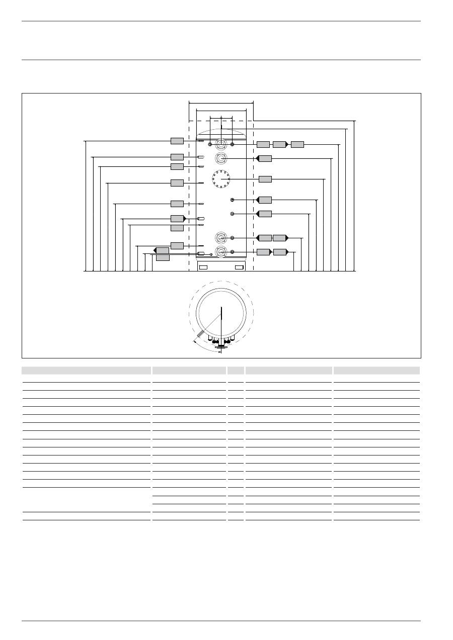
13.1 dimensions and connections
sBP 1000 e | sBP 1000 e sol
175
175
790
1010
262
522
902
1122
1452
1777
1997
2240
2340
302
277
400
730
827
1060
1390
1650
1800
2050
e01
d36
d02 d36
d25
d01
e02
d35
d35
d26
h22
d46
d47
h43
h22
h22
h28
h02
i07
i07
i01
45°
D
00
00
01
73
90
sBp 1000 e
sBp 1000 e sol
d01 Heat pump flow
Diameter
DN 80
DN 80
d02 Heat pump return
Diameter
DN 80
DN 80
d25 Solar flow
Female thread
G 1
d26 Solar return
Female thread
G 1
d35 Heat source flow optional
Female thread
G 1 1/2
G 1 1/2
d36 Heat source return optional
Female thread
G 1 1/2
G 1 1/2
d46 Ventilation
Female thread
G 1/2
G 1/2
d47 Drain
Male thread
G 3/4 A
G 3/4 A
e01 Heating flow
Diameter
DN 80
DN 80
e02 Heating return
Diameter
DN 80
DN 80
h02 Sensor heat pump return
Diameter
mm
9.5
9.5
h22 Sensor heat source
Diameter
mm
9.5
9.5
h28 Sensor solar cylinder
Diameter
mm
9.5
9.5
h43 Thermometer
Diameter
mm
14.5
14.5
i01 Flange
Diameter
mm
280
280
Pitch circle diameter
mm
245
245
Screws
M 14
M 14
i07 Electric emergency/booster heater
Female thread
G 1 1/2
G 1 1/2
20
| sBp 1000-1500 e | e sol | e cool
www.stiebel-eltron.com
installation
specification
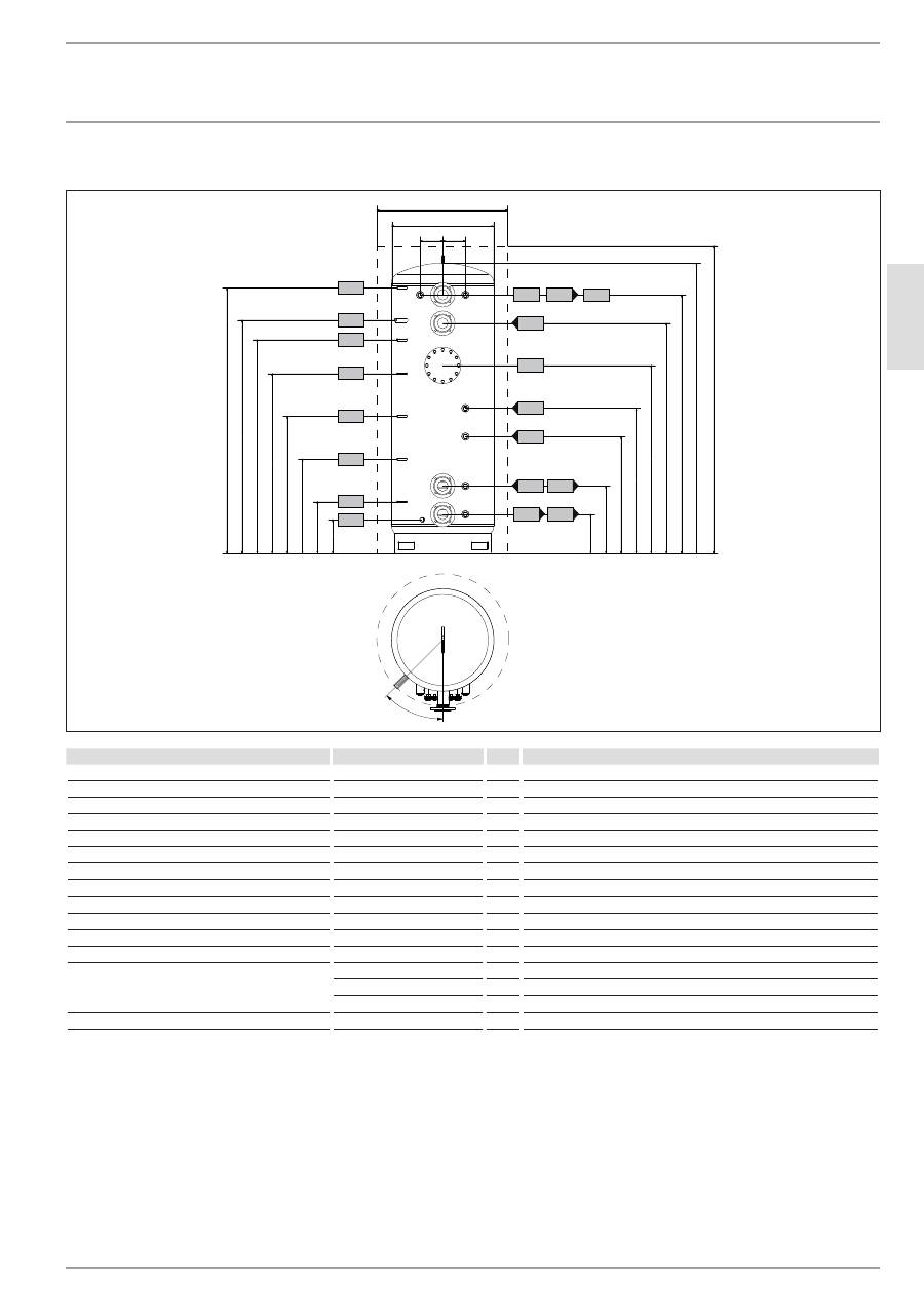
sBP 1500 e | sBP 1500 e sol
175
175
1000
1220
349
609
956
1179
1319
1629
1849
2240
2154
389
364
464
759
914
1054
1349
1600
1710
1900
i01
i07
i07
h22
h43
d46
h22
h22
h28
h02
d47
d35
d01
d35
e02
d26
d02
d36
d36
e01
d25
45°
D
00
00
01
74
06
sBp 1500 e
sBp 1500 e sol
d01 Heat pump flow
Diameter
DN 80
DN 80
d02 Heat pump return
Diameter
DN 80
DN 80
d25 Solar flow
Female thread
G 1
d26 Solar return
Female thread
G 1
d35 Heat source flow optional
Female thread
G 1 1/2
G 1 1/2
d36 Heat source return optional
Female thread
G 1 1/2
G 1 1/2
d46 Ventilation
Female thread
G 1/2
G 1/2
d47 Drain
Male thread
G 3/4 A
G 3/4 A
e01 Heating flow
Diameter
DN 80
DN 80
e02 Heating return
Diameter
DN 80
DN 80
h02 Sensor heat pump return
Diameter
mm
9.5
9.5
h22 Sensor heat source
Diameter
mm
9.5
9.5
h28 Sensor solar cylinder
Diameter
mm
9.5
9.5
h43 Thermometer
Diameter
mm
14.5
14.5
i01 Flange
Diameter
mm
280
280
Pitch circle diameter
mm
245
245
Screws
M 14
M 14
i07 Electric emergency/booster heater
Female thread
G 1 1/2
G 1 1/2
www.stiebel-eltron.com
sBp 1000-1500 e | e sol | e cool |
21
EN
G
LI
SH
installation
specification
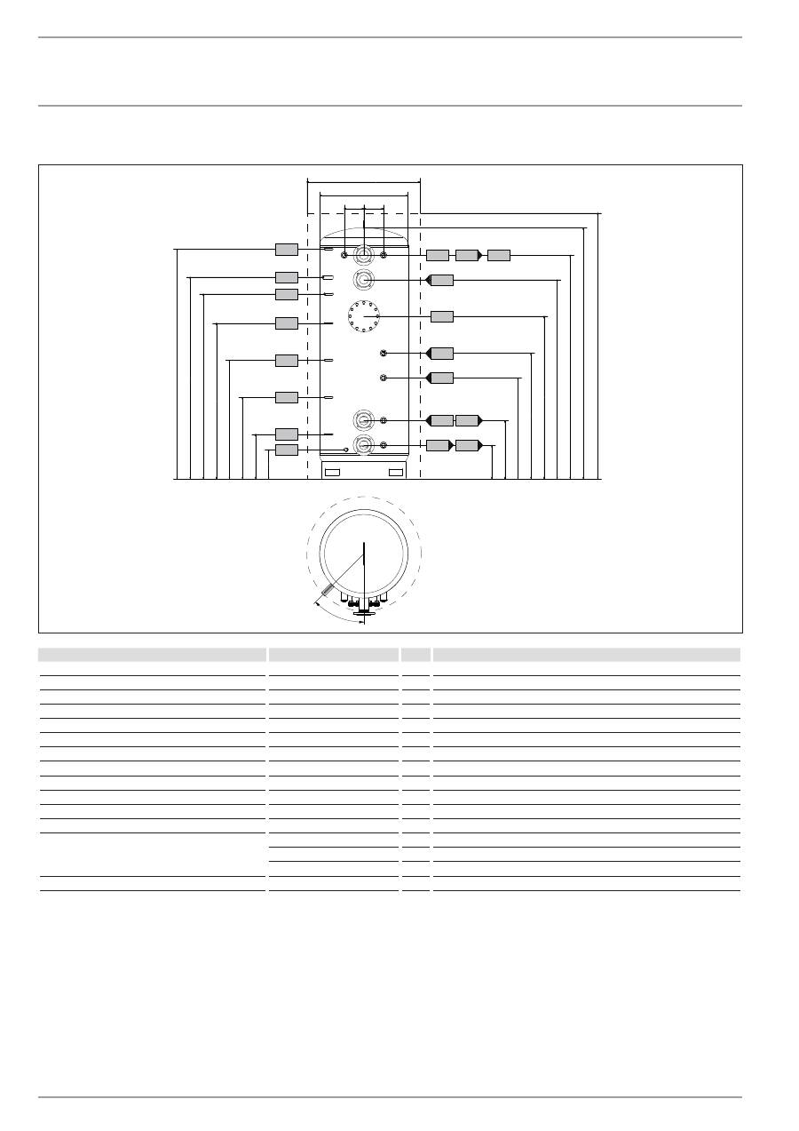
sBP 1000 e cool
175
175
822
1010
262
522
902
1122
1452
1777
1997
2240
2340
302
400
730
1060
1390
1650
1800
2050
i01
i07
i07
h22
h43
d46
h22
h22
h28
h02
d47
d35
d01
d35
e02
d02
d36
d36
e01
45°
D
00
00
01
74
21
sBp 1000 e cool
d01 Heat pump flow
Diameter
DN 80
d02 Heat pump return
Diameter
DN 80
d35 Heat source flow optional
Female thread
G 1 1/2
d36 Heat source return optional
Female thread
G 1 1/2
d46 Ventilation
Female thread
G 1/2
d47 Drain
Male thread
G 3/4 A
e01 Heating flow
Diameter
DN 80
e02 Heating return
Diameter
DN 80
h02 Sensor heat pump return
Diameter
mm
9.5
h22 Sensor heat source
Diameter
mm
9.5
h28 Sensor solar cylinder
Diameter
mm
9.5
h43 Thermometer
Diameter
mm
14.5
i01 Flange
Diameter
mm
280
Pitch circle diameter
mm
245
Screws
M 14
i07 Electric emergency/booster heater
Female thread
G 1 1/2
22
| sBp 1000-1500 e | e sol | e cool
www.stiebel-eltron.com
installation
specification
sBP 1500 e cool
175
175
1032
1220
349
609
956
1179
1319
1629
1849
2154
2255
389
464
759
1054
1349
1600
1710
1900
i01
i07
i07
h22
h43
d46
h22
h22
h28
h02
d47
d35
d01
d35
e02
d02
d36
d36
e01
45°
D
00
00
01
74
23
sBp 1500 e cool
d01 Heat pump flow
Diameter
DN 80
d02 Heat pump return
Diameter
DN 80
d35 Heat source flow optional
Female thread
G 1 1/2
d36 Heat source return optional
Female thread
G 1 1/2
d46 Ventilation
Female thread
G 1/2
d47 Drain
Male thread
G 3/4 A
e01 Heating flow
Diameter
DN 80
e02 Heating return
Diameter
DN 80
h02 Sensor heat pump return
Diameter
mm
9.5
h22 Sensor heat source
Diameter
mm
9.5
h28 Sensor solar cylinder
Diameter
mm
9.5
h43 Thermometer
Diameter
mm
14.5
i01 Flange
Diameter
mm
280
Pitch circle diameter
mm
245
Screws
M 14
i07 Electric emergency/booster heater
Female thread
G 1 1/2
13.2 Fault conditions
In the event of a fault, temperatures of up to 95 °C at 1.0 MPa can
occur depending on the type of heart source used.

www.stiebel-eltron.com
sBp 1000-1500 e | e sol | e cool |
23
EN
G
LI
SH
13.3 data table
sBp 1000 e sBp 1500 e sBp 1000 e sol sBp 1500 e sol sBp 1000 e cool sBp 1500 e cool
227564
227565
227566
227567
227588
227589
Hydraulic data
Nominal capacity
l
1000
1500
1000
1500
1000
1500
Contents, indirect coil bottom
l
25.9
31.2
Surface area, indirect coil bottom
m²
3
3.6
Pressure drop at 1.0 m³/h indirect coil bottom
hPa
8
9
Application limits
Max. permissible pressure
MPa
0.3
0.3
0.3
0.3
0.3
0.3
Test pressure
MPa
0.45
0.45
0.45
0.45
0.45
0.45
Max. permissible temperature
°C
95
95
95
95
95
95
Max. recommended collector aperture area
m²
20
30
Dimensions
Height
mm
2240
2154
2240
2154
2240
2154
Diameter
mm
790
1000
790
1000
822
1032
Diameter incl. thermal insulation
mm
1010
1220
1010
1220
1010
1220
Height when tilted
mm
2335
2250
2335
2250
2335
2250
Weight
Weight (full)
kg
1172
1729
1184
1750
1141
1698
Weight (empty)
kg
172
229
219
285
173
230
installation | Warranty | environMent and reCyCling
specification
Warranty environMent and reCyCling
Warranty
The warranty conditions of our German companies do not
apply to appliances acquired outside of Germany. In countries
where our subsidiaries sell our products, it is increasingly the
case that warranties can only be issued by those subsidiaries.
Such warranties are only granted if the subsidiary has issued
its own terms of warranty. No other warranty will be granted.
We shall not provide any warranty for appliances acquired in
countries where we have no subsidiary to sell our products.
This will not affect warranties issued by any importers.
Environment and recycling
We would ask you to help protect the environment. After use,
dispose of the various materials in accordance with national
regulations.
