Stiebel Eltron DHE 18 SLI 25 A – страница 2
Инструкция к Водонагревателю Stiebel Eltron DHE 18 SLI 25 A

D
T..............
-v=^
</>
wt
_l
U>
W W
®
4« Brilli IC-
„ Щ0Г
&aCl /^i1
-------
--•? -Ci'
I '•Vv-I.
__ ___ __ __
J
3
®
H
l»
lüO nn
1 _
1
30 пт
I 1 1
.»F
i LJ
Í —
'ÜV¿^
,d.
Г"И
II
i
23
-----------
-
....
I
----
1' li
L1V L2> L34
a
lì
ttl
.......
"■ ■
'1F9>'.'5^5>4
L fe L
I ■. I
......
: дщщ
3/PE - 400V
:m
У)

STIEBEL ELTRON
'dl/
1« Operating instructions for users and contractors
1.1 Equipment description
1.3 Recommended adjust
1.5 Important information
Description
ment, thermostatic vaive
A If ihc w ater supply to the D HE has
The w<*te' heater D HE...S Li
Tc safeguard the f.^^cion o't^e iherm cTatic
c Ij been interrupted. e.g. because of a
electronic com fort he<*.ts w ater ¡is it flow s
•v^lve.the D KE ... S L nr.,»: os set to t's rraxi-
risk of frost, or w ork on the w ater pipe,
t'-ro^^h t'-e équ'pirèntThè hot-w xer outlet
m ..n tsripsrature (60 X ).
ihc follow ing m easures m ust be taken prior
tenpe'silure is rf'•nel/ .id ufta'ole oetw -een
to bringing the appliance back into use:
2C *C .inc Ó 0 *C “he <e:teirper<-.t^re <
1. R em ove the ftjses and/or trip the M C Bs.
1.4 Safety instruction
show n on t'-e d spia/ Froir a low tta o'
or sw itch off the D HE ... SLi by m eans of x
2.5 l/m in upw ards, "he ecuipnent is sw itched
There is 2 risk of scalding at outlet
the tem perature selector (“O FF” positi- *5
by the e eci'c'-ic co'-t'c u^h Thc w ater
c_L^ temperatures above 43 X.
on). to
is heated to exactly the set tem perature by
Wiiere children or persons with limited
2. O pen a draw -off valve dow nstream of S
m eans of the fully electronic control unit
physical, sensory or mental capabilities are
the equipm ent until all air has been pur
with m otor-operated valve.
to be allowed to control this equipment,
ged from the cold water supply line and
ensure that this will only happen under su
the equipm ent.
User interface display:
pervision or after appropriate instructions
3. R eplace the fuses and/or reset the
The disol«*.ys C:in be chiinged 'nd vienili/
by a person responsible for their safe^.
M CBs or sw itch the D HE ... SLi back on.
As de iverec. the factory sett n^i of the
Children should be supervised to ensure
EC O operiTrion <*.re 8 rtr&s.''in '•^te .ind w ith
that they never play widi die equipment.
.iuton«*.tic
0.1C diglring.W rh these setti'-gs.
Risk of scalding^
1.6 First Aid in the event of
t'-e br.cl< i^t '■¿ sw rehes on <*.s soo'- as the
If cfiis is unavoidable, we recommend a
faults
tem pe'-rture selector or a button :s <*.c:i-A'“ed
permanent temperature limicThis can
• Cheer, the fuses
c'lhe equiom ent is heati'-£ uo. “he bac<-
be enabled witfi the functions *'Chifd-
• Chec r. that t' e *rt:ings ¿nd show e ' con •
Il¿lт:in
2 sw itc'-es off .i^er 3D seconds w ithou:
proofing’’ (see 3. Convenience function
tfcis are free o’■im e5cгle or d'T contam i
ooei*t'o' or '83:in§.
settings) or *'Ant1-scalding protection’’
nation. see also”8. Faultfinding - U ser'.
I Ik: l«r.,r:'y s.'lli";il h<; xlk;rx;c l;y ‘ iiSvf
{see 10. Service mode) on die DHE ...SLi
(»•cc ”3.3 Setting the comfort functions"Jl.Yr>..
pro^amming unit.
1.7 Care and maintenance
rA i fx:.ur- .h:i Ui :: ystilli -ct u\i-;j Ihc M1
wic M2 )ij l-nri.v
yX Mainienance work, such as diecking
Pfx;i:s I t; IniUfVi logdhcr •>(;(.x)ric>.
r I I electriol safe^. may only be carried out
by a qiolified insciller
The equipm ent c.in be coeratec using a re
m ote <.zrxro\ (see “10. Special accessories'’).
AI Ihnl i.> ri(;(;c!.;!l lo duH " Ik: h(Hi:>irig i:> n
(Ui*i.) ('f:lh. Do "r:l me ^n/ ^hrav vc or f h-.i-
1.2 Hot water output
vlif (suhsUfKC'..
Cole w ater te ripe M tures w .ry depencing on
t'-ecim e o'vecr.Tlie fol o'w - '-g rifix’m um out
1.8 Instructions for Installa
put vc'uires. C -' m ixed w <*.te'volum es can be
tion and Use
.ich'ev'ed w rhtliese dffe'e'-t cole w .iter inlet
tem penatures (seeTib'e 1):
yX Follow these instructions carefully, and.
ft, “ C c'd vv<"er rle:terr:oer<*.t^'e
< ^ in the event of change of ownership
ft, : 'lix ng w r.te ' tern aerate 'e
pass diem on to die new user. If an/ mainte
ft, - C^tou:‘:eroer<*.t^'e.
nance or repair work is necessary, them
• Useful ccmpcraturc:
to the qualified installer for him to read.
-approx. 38 "C: For exem ole. for show ers.
^.inc b<*.srs. filing baths, etc-
- approx. 60 "C : For disliw .is'-ei s a^d 'w-he^
^si'j§ thernosti-t'e fittings
® 38 *C (Mixific vvHicr lenite-Hlurx:)
19 kW 21 kW 24 kW 27 kW
VfT ifi **
6'“C S .D 1D .7 12.1
10 ^y.) 10.? i?,j rs.w
14 X 10.7 12.3 14.3 1Ó .1
ft, = 60 (O utp’jttem peniture)
19 kW 21 kW 24 kW 27 kW
./irin
6“C 5.6 S/ 7.2
10 X .5.7 r>.D 6.9 /;/
14 X 5.6 6.5 7.5
Ul)le 1
I hn vxl..e.i n Ihk l;i')le -:;lHle lo :>ij|)|;l/
vol.Hge of "!)DV. I he «r..uH ou le. vx)I..tk; iv
'Kr)jc( I lo l-':e Hv>iil>i‘)k! supoly |)rx:v-.urx: xrie
l••iifl.^ vx)IIh;ì:v
7‘3
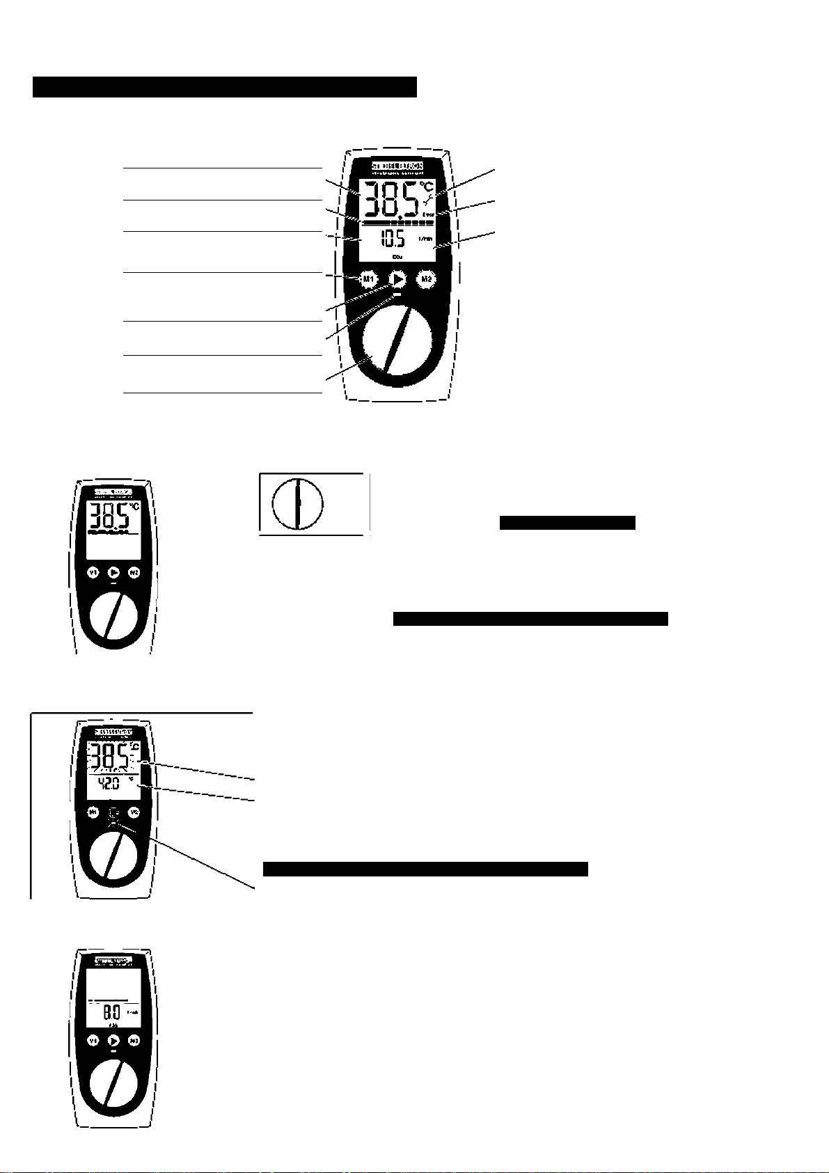
2* Operation ■ ■ I>ri6f ** for users and contraccors
2.1 At a glance
Tem perature display
Service
Bar display to Indicate pow er
Error i fault display
Second display
Backlighting
e.g •lo'.v r*"8
M em ory buttons M 1 and M 2
Function button
e.g EC O
Seal di ng w arning d isplay
Tem perature selector ^
2«2 Setting the temperature
Infinicci/ adjustable temperature selection
• 20 CO 60 "C
if
OFF Heating is sw itched off.
Memory buttons
0 0
fer iv.pid svvhchi-'-g between p e-selectec teroeratL &«
• Scoring chc desired cemperatuici
I ’^x :S!- l( >r I v-n)ir < )n< Is.
Tempersture display flashes once and is stored
Selecting a stored tem perature:
Press c ■ -
2.3 Warning displays
Flashing warning light for excess temperature
If "he 'le: terr?er*t:.rs is 'igh«' "ban t's ce sired 1err?erc't:.^. s g. c's a result cf sok'r heated vvc'ier
vsterr^erc't:.^ cisplay flashes and the second di>p ayshov.'5the inlet teniperature.
le m pe racure d i >p lay f la she s
Second display - inlet tem perature
Scalding w arning display
Ciution:'niere is a risk of scalding at tem peratures ^ 43 ^C !
Colour changes from green to red
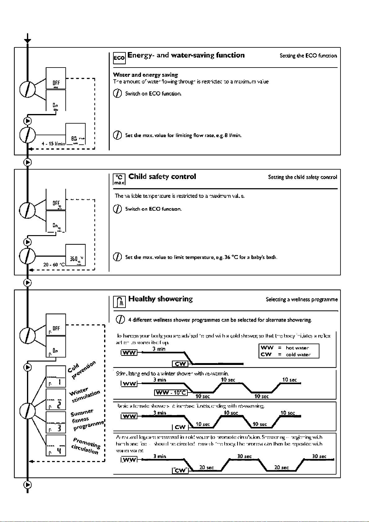
2.4 ECO function
Water and energy saving
The quanti^ of w ater fitw ving through is lim ited to a m axim um value
(Factory seccing 8 l/m 1n. a different value can be set in die m enu).
EC O on ■ > E CO sym bol In t^e dspliiy
EC O off ■ > no EC O syrool ’ll the displ<'.y
74
STIEBEL ELTRON
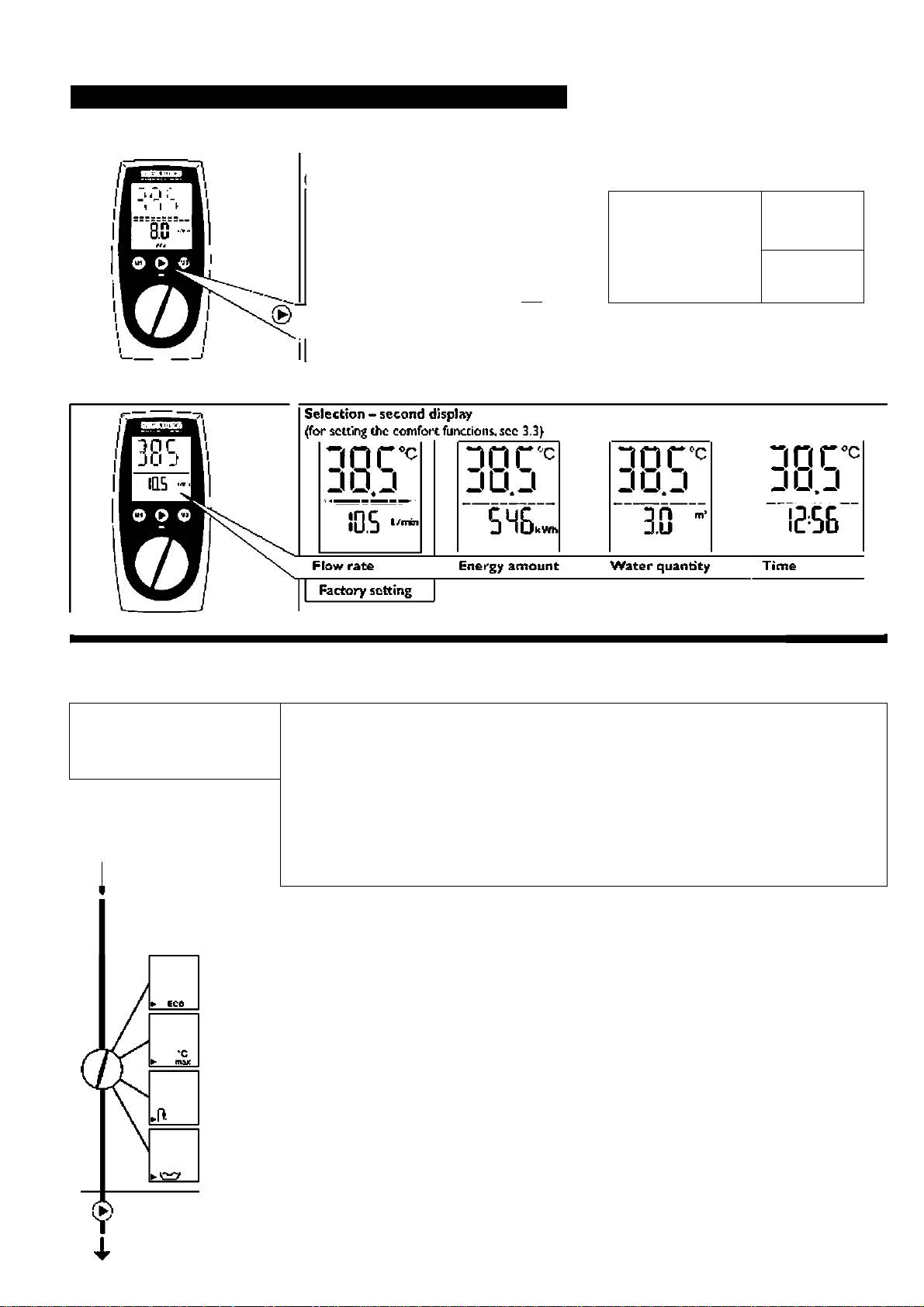
3« Setting the comfort functions for users and contractors
3.1 Function button and possible settings
Comfort functions - overview
Yor scccing the comforc fuitccions, see 3.3)
DCrr
30 C'""
JO.^
JO.U
JU.J IIJ.J
on ,,
inr
inc , ^
</>
O.LI
qS
.lU.D
IIJ.J •
wt
”c
ECO
tnix
9
Healtl^ showerifig
Water quantiQr
water«saving function
program selector automatic
Factory sotting
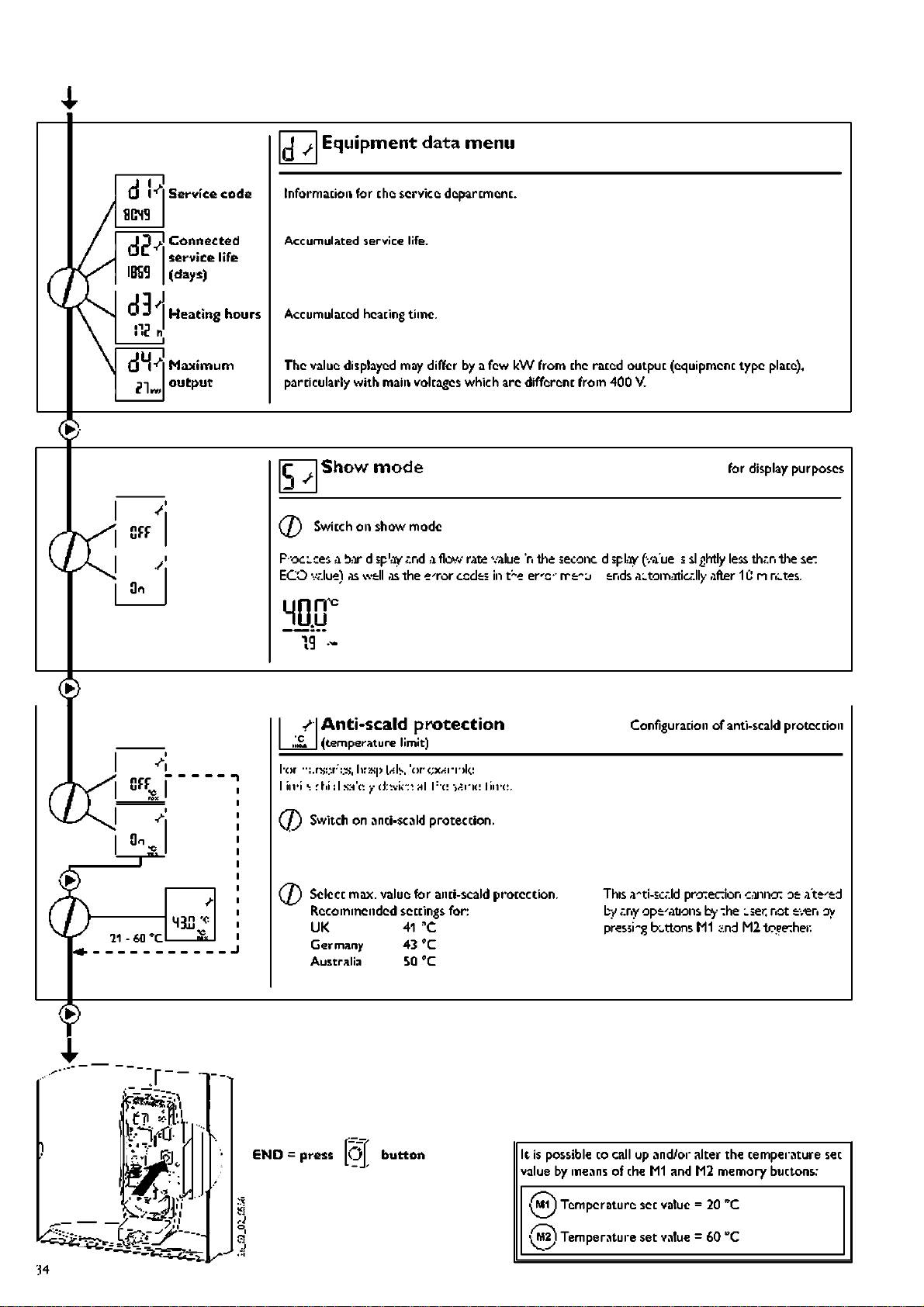
3«2 Second display for reading out information
3.3 Setting the comfort functions
The com foit functions can be set
START P ressforlseconds
or selected one after die ocher.
The settings aie incorporated
im m ediately.
( / / Select function and set value
Scroll through the m enu
START
1 P ress for 2 seconds
EN D (^} Press for 2 seconds any point
^ Kutom nucally after 30 seconds from last setting.
Function button Assigning the function button
Energy* and
water*saving
Snvcrvil i:.nr .ion*- (H" l;c m Iìvh.c:I h. liic '{H ric li‘'i(!.
A «.cIcdcH l:."( lifv' hvr liic«: (a- i:<: '•wilc-'nil on O^^o ' ^rsing liii: iiiil.fv'.
Child safety
control
Function selection.
Wellness
Note-
showering
programme
Eco.nwx.f^- liic iunt liori'- Hc M I’vHlcd hy |)rx:'-%i;i^ liic hu.':v H"d a:',', only dc-n: livnlcc' i:-y
p.'ess ng ii':e button A ga
Water quanti*
ty automatic
Press ng ii':e button fictrvvites the fLiic:ion on y once fc • ihe .';ext process of drcvv-
control
ng o" w ite* fi'-d the function is autoriticA ly sw itched of it "he end o'the process.
’>Ь

STIEBEL ELTRON
Water <)uantity automatic control Scccm g chc w accr quanti^
aucom acic control
t the pre-seleced voluire i& reached "he r.irc'iutic control i eduoss the flow r;.te ~.o aoprox. 4 l/irin.
OFF
Excnole: bath tilling 8C II.
When BO I hccfi rxi;<c":iil, w 4 rxicu: .ion lo «|)|V7:x. 4 |/;ni ';lc.st v.-^ nr.-iirrply r..ivi in.
I (Icsirxtc .nrv)nr*al..e7 fx:mw'’s eryt-wil.
(2) S witch on the w ater qvianU cy autom atic control.
</>
wt
Set the m3x.v3lue farwscer quanti^, e.g. 80 I.
5 • 200 llJasL
Note;
The w ater quantity autom atic control m ust be operated before filling the bath. O perati*
on applies for one filling of the bath only.
Second display Assigning chc second display
©
Flow rate
Any desired v^lue on be shown in tlie second display.
Energy
eonsurnptTon
Select tlie v:»lue.
Water
aa
quantity
о
Note;
Select the valycN occtIn thc"kW h‘‘ and'W " n»cnus,ihc m eters can be reset lo ZER O
Time
by pressing snd togetlier:
laao
О
Clock Setting the clock
©
Set the clock.
Ф
00<I0... 23:59
Р.егггг<;
P.e-5et гпе' a pows' cjt
Display lighting Set display lighting
□ flashes on Ruto - sett ng.
Яи to The cisplay-backlight sv.itc'ss tself a-tom 3tic-.l у off ¿nd
Ф
O N: w 'S ' heatng jp w ¿te'a'd w it': eac' operation.
O FR a^ter 30 seconds w ithou: operation.
Bn
Tontinuous li^h: on.
Ф
Note:
Press for 2 seconds
Press 1Ù U and for 2 seconds resets foccory settings.
END
Г/
.я/
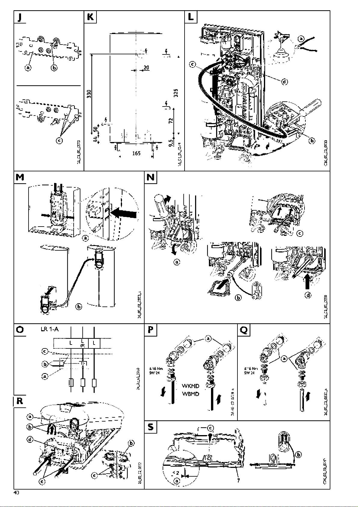
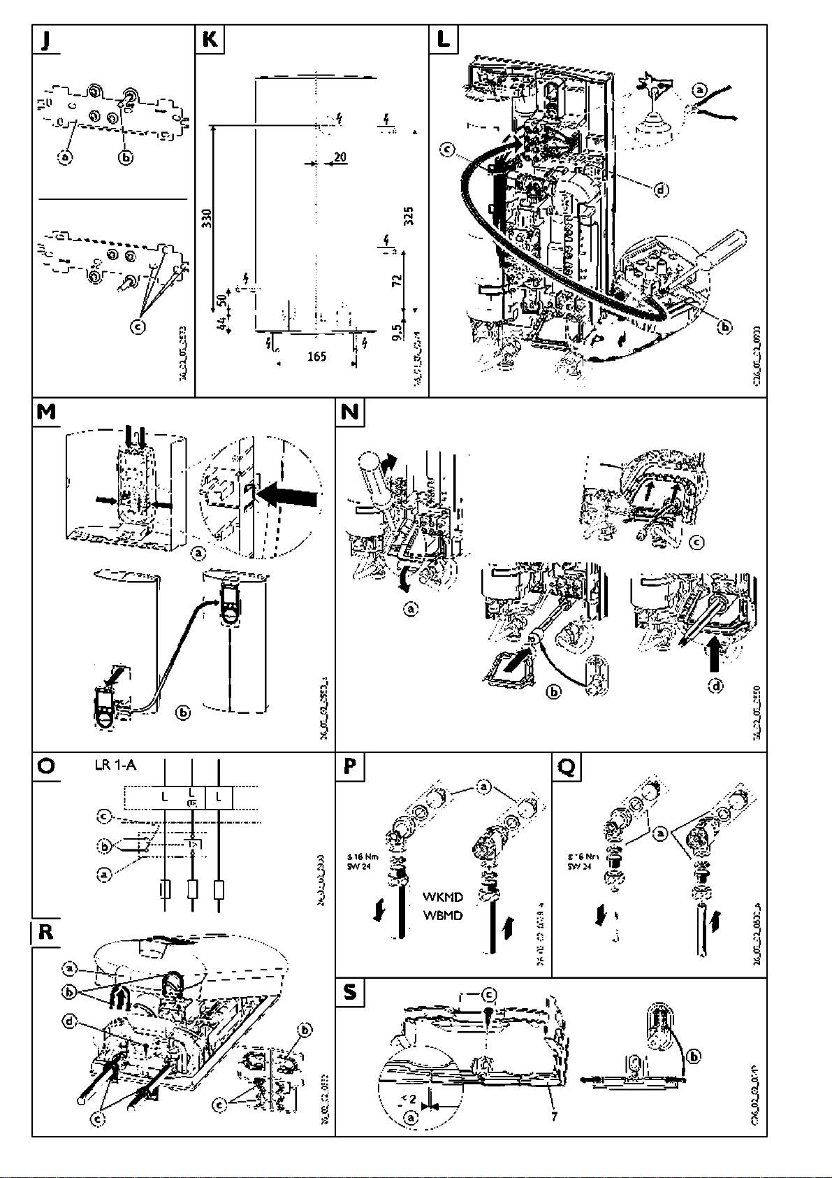
4. Installation instructions for concraceors
4.1 Brief description
4.2 Important information
4.Э Instructions and
I "ii mi( -i:4:"lr-;:ll(:(l ¡пх1лп1лпс()и'{
Air ci'appcd in chc cold w ater supply
regulations
v/hIc hcHicr DHE...SU ‘.vilh 1..П/ i^lcdrOrii-:'
can dam age the tni% wire heating sy
* T'è ratal ¡Trion (•vW .té ' A'd e èctried
Ci: is и p ccvkc l-:i OIN
stem inside the equipm ent or trip die safety
•л'бг<; <*.nd conm issien'-g, :is '.veil :is "he
suilH lor l;:c hcHli"^ o 'г old w« :т-::г f-:v
system (see *‘1.S Im portant inform ati*
.nante'-<*.nce of "his eq^ipm eir;. nust c'ly
Ihc o ‘v.>il(:- лЫс" hns :>n>
on**).Thc DH E...S LÌ is equipped w ith
oe CT.iried ал by aquarlec coiTrraccc' in
■сл-:'л\ ioS9,*X:.
an air detector w hich, to a great ex*
<*.ccc.rd«*.nce w t' ihese instructions.
I • mHxi fiijff |:(;-i::i l(;-H i"k:, к:п:|ч:гл1..п.'
tent, prevents dam age to the heating
* Perfeaf^'C Tion <*.nd safe cperat’c' сд'
Ч r>." “C^ I he (:('iii|:‘ri(;nl •пну he (1н г1я;>:ч1
system :
cn!y be gg«*.ra'teec w hen us’'^ crign:il
л1 higher lemperH.ijfx:'- Л1)о*;е hS I' ii
If. during opem tion, air is draw n into the
accessories <*.nd sp<*.re oarts intenced for
•fiesiH^t: "Error" л|)|>:'^Гл in I he di.>|)lny. I he
DH E, the equipm ent shuts dow n the pow er
th!s equipm ent
riHX 1*111^1 nle. U:fï‘|)errt'..rx: C«n y.^ ii::i i.xl lo
fo.' a one m inute«thei\2b/ protecting the he
* O oser'/e д I loC iil у <*.pp ic<*.ole instruaiens
t/.) “CI \A/ilh l"o"f eri.r«! Ihe ieosIrtI" 4,>orwl
ating system
<’.nd enubdons l egri di'g-w viter ¡ind
A: (( :'-л( )гу ('{( :e " 10. Spec iai a cces so ries' ').
e ectrical connections, such <*.s D IN 198S .
or ¡'lorx: (1гл'л--о":)Г:1пЛ ran he ^u|>:)l ed
• Valves:
DI\^109.D N'V851 etc.
•лИМ 'l•l!.í ee..i|!.TK:n,.
• St’éoel E hi’on ji’essuie w ives for insf.n-
* O iise.'ve a I local water ¿nd electricity
I i::i(ro|:'t:e:ri<”Ofs-conlrol od il(r-,-v li•niler
f.neous heaters.'or nstilaticn o'-
supply сспргпу 'egub.t o's.
rtiway'-en<-./o4 Ihrt .he sol .oi’ioornlii-o is
fnishsd w *lls (see *'10. Special accessori
* Install t's low s' a'sa of t's eq ^ ipm sm
e.?rhee.
es’’;-
fush w ith the w *ll (obssr-/s cinrs'sion
I ' o l«rx: V.TO hcrtl'n!^ '>/sU"ri iv >u 1«Ы<; ie-
• lnstr.l *"ion nay be earned ou: .^sing conr-
> Г0rnE;.
v.vile.‘ wi,h low l¡.•тleчrtle o"\Aiilh Irriew^le
m erda ly ¿va'lab's p'sss.^rs '.'¿K^es.
* T'Slype pb-ts Горел the h'n^c ^гр on
ee' lenl (хее "7.2 Application ranges**}.
• Ther.noFtatic p'sss.^'s -tfi-lves
the squiorre't cap).
'‘1.3 R ecom m ended adjuscm enc").
* See ¿Isc '7. S pecification".
Apptiâiice with Output options
lo'-ihei:-! I i insl^n'rtneou’-
• Al rforn*tb' r "hese o?er*t'ng anc
yx The specific electrical resistance of
v.'Hler healer; l"o ou pul ч ad inia do ‘n lhrx:e
instr.ll*t'o' i's:r.,ctb's m ust be foila-zvec
the water m ay not be below the value
.>lnj^es. n l.i •Holivoilxl {'ry'dilion h o aopliarirt:
caref.,’ly:“hey cornai' inporta't deta'Is
written on the rating plate.
•) se IO /1 kW
rsga'di.ig sa'sty. operation, instr-ll^don ¿nd
If the w ater îs com ir\§ from a vrater-net*
l."lhe apoliarxe i'- irislalled XArilh adillerxiril
nairrrsnancs of the e qui one't
work the low est value of the water resist
■oulp'.:l.‘ake !••(: (dkv/in^’■Icp!':
ance m ust be considered, (see „7.2 area of
• RepliJ!^ rodi"^ <лгх: on Ihe лроИлг^ге 14". *>
application’*).
а'ил.х; l"o ¡"iori'irtlio" 1лЬ(;1.ас!.огхГ"^
The specific electrical resistance of the
water is generally know n by t!ie w ater pro
.о .he oul|:..l xeleeled. I or.-aled :urev.l
vider.
a"d l.:so. ч:е SoedI rali-on.
• r-'ark l;:e ‘e or od oul|:..l r>" Ihe lyoo
* Install t'è eq^ipmeiTi only i' ¡in enclo
|:'a,o wilh a рег'па'ч;"! О1агчог:
sed, frost-fi ее 'ooir. Store cisTia'ted
ecuipment in f'cst-f*ee concitior.5. s r.ce
there is a-vv<*.ys ¡i lltle w<*.te' left inside t'e
ecuipment
* T^è protection level IP 2S (rcse-proot}
s o.ily gUiirciTieed i'<*. correctly instdiec
cr.ble groiTnet is usee.
Water installation:
- C o d w ete ■ pipe m ate-'i/il:
ii.ro|)|:c'or :)Ih .-! к pi:):: sy-lcrr-i.
- )l W* pi:):: тн1сг:я1*
Cooper O ' pl:istc oipe sys:em s=^
<!:)::гн1 Ic-ripc H .ijrX ;su|! .Г:-н I'lax.
60 ‘'C ca' be reached w t' the
)l II ...i;i i ¡п'-1н"1лп:.:х>..-)'ArtU;'h(;H l(;r:
■'"эх nun- lci.ds of 80 ■'C / ' .0 '"Pa n<=y
()(c.:'l?-icly i-- ,hc n^lH 1н11::п in ■
e\-ent cf a fault The p ¿stic pipe sy-ste m
us::d •nu'-l he dc'-jince .о'ч-..:Ь i-c'-di-
tions.
* A s?.fsty -tfi-lve is not i-ec.,ii-ec.
* N ever use va'^ss fo' open syste m s
Electrical installation:
* E'sc:ric3l connection o'ly to oerm ane'ty
wi'sd m a ns power ca:)les
* T's eq., ipm sm m .,>t :>s a:)le to :>s cis
cc.^'ected from the m ains pow s's.,pp 'y,
for sx?.rro!e by f.,ses that disco"sc: all
oolss w rh at least 3 r m co't?.c: separati
on.
7F>
STIEBEL ELTRON
5« Standard installation fai*CDrttractor&
Electrical: unfinished w alls-from below : water: unfinished w alls
sdcd'rvi I lo l;:c ::l I"::
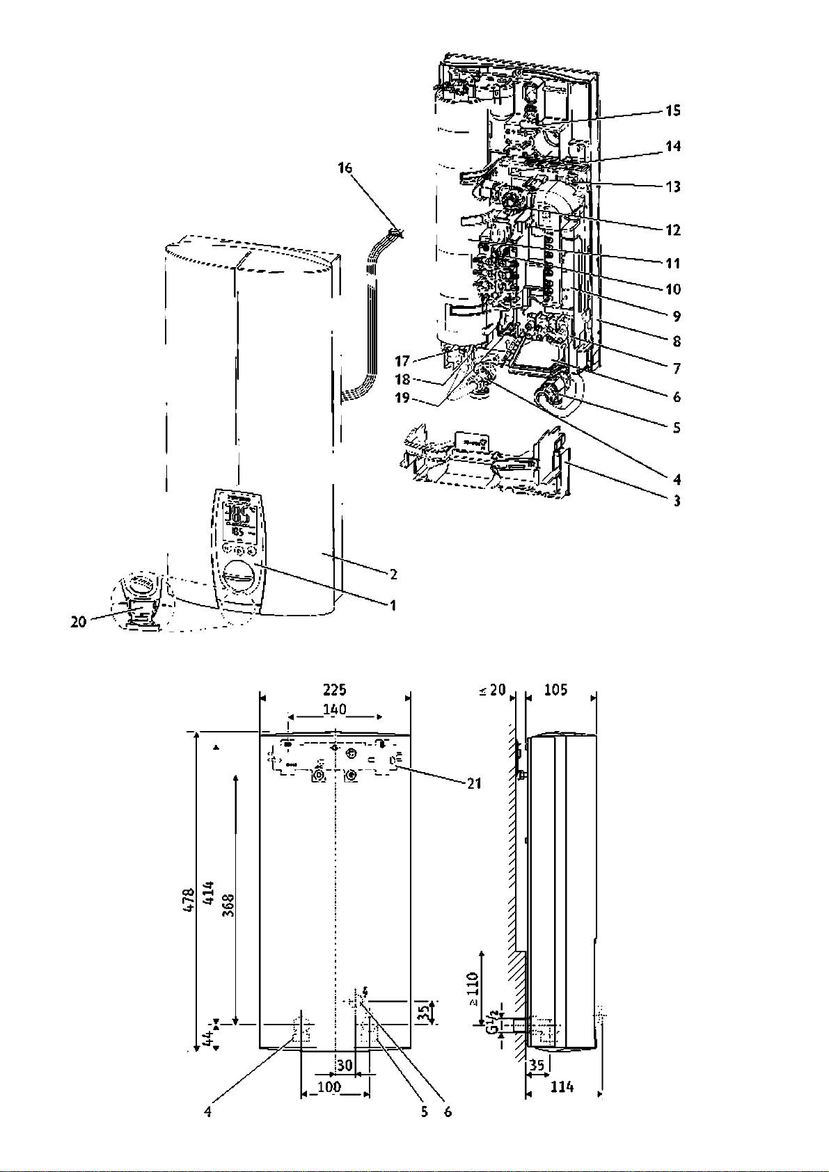
Key eo figures . [^
fitting) into die col-J-water' compression fit
'::l(W rtnl v .-'h II).
1 Use'i'terfice
ting. Wfien nepl:icingt!ie insttllnion,c!ieck
2 Equbner:t cip
5.5 Trimming the power
ciiat the strainer' is in place.
3 BasC i b^ck v\v.l
4 I5I VV (om prxrsiion ii I 'nj^
cable to size
M ove.' use the: chroo-w ay shuc-off valve (5)
5 C ok w :iter cc'iip essio'- Iting
Iri n l"(: Ixj'A-x:'(’«•)!(: lo xi/o in «rcorxrrtnco
CO reduce ebe: flow rate:.
6 C a:»!e gronrrist ielectn«.! sup^lv ca:>l8
v/i h J4j.
fen oelovv'
Note:
5.8 Electrical connection
7 M?.ins ■erTriin?.!
Cao (a) shouk be used as <*.n <*.id 'c ■ ¡'•st!tl ing
Cc"&c: the e ectrkal suoply caole to the ter- ^
8 lo|), •yni 'i wn I
t'e pow er ctble.
irinal St ip (seeWiring dbgrair
9 Electronics
10 vw 'li !-(Al i)-.vilh nnci-xjilon
Important information:
5.6 ^uipment installation
11 sysien
12 Flaw'ate rrstf-sunn« ip Fill
The protection level IP 25 (hose-
» Rc.,t€ t's pow er c?.ble t'ro.,gh t*:« ca:»le
13 iiocc:! i:r st:l vh u:: krtn'-diKor
¿.Lj prooO can only be ensured w ich a cor
14 L: D c cstic' 'tr<'.ltk lights'
gronne: i6; a'd oress the baci.w all eve.'
rectly fitted cable grom m et i6) and seal
15 I i>: ns^ lo^k
the t'reaced 5t.,ds of the nounting b-'a-
on the cable bush.
16 Set V A u& •tr<’.nsducer c^ib e plug
eke:.
Connect the equipm ent to earth.
17 Safety t'SH Tial cut out (STB)
» Ft the eiuip nsnt, seu.i'e the ixi'g toggle i1 S).
ia O ijik ^(¡•••■ioriN IC )
19 S'<*.p-i' tsib •or sub-r<*.ck (se vice)
5.9 Completing the
5.7 Water connection (S
20 U I H .iric |! h Ic
l.'nportnt in'biTn;ition:
installation
21 M ounting oividtje:
1. 0|:<;" ,h:.: lfirx;(;--.v>iy •>h..l-o"valv::
(S).
22 St'v.i'er ir. the cold w TO r corrio'ession •'fc'n?
Thoroughly flush the cold-w atc.' sup-
23 lilii-c
2. i;i ■••::f:«rk wxl f:,?^(:E(3).
ply pipes.
♦
Alw ays incorporacc the strainer and fiuir\g
LED diiignostic ^traffic Lights''
supplied (22 and 23. bag on the colcl*wacer
red illurm nales in ciise of fjulls
____
io»o VC Ho appliance Is heating water
_______
flashing: The appliance Is upplicd
,reen \»i'ith powftr
___________________
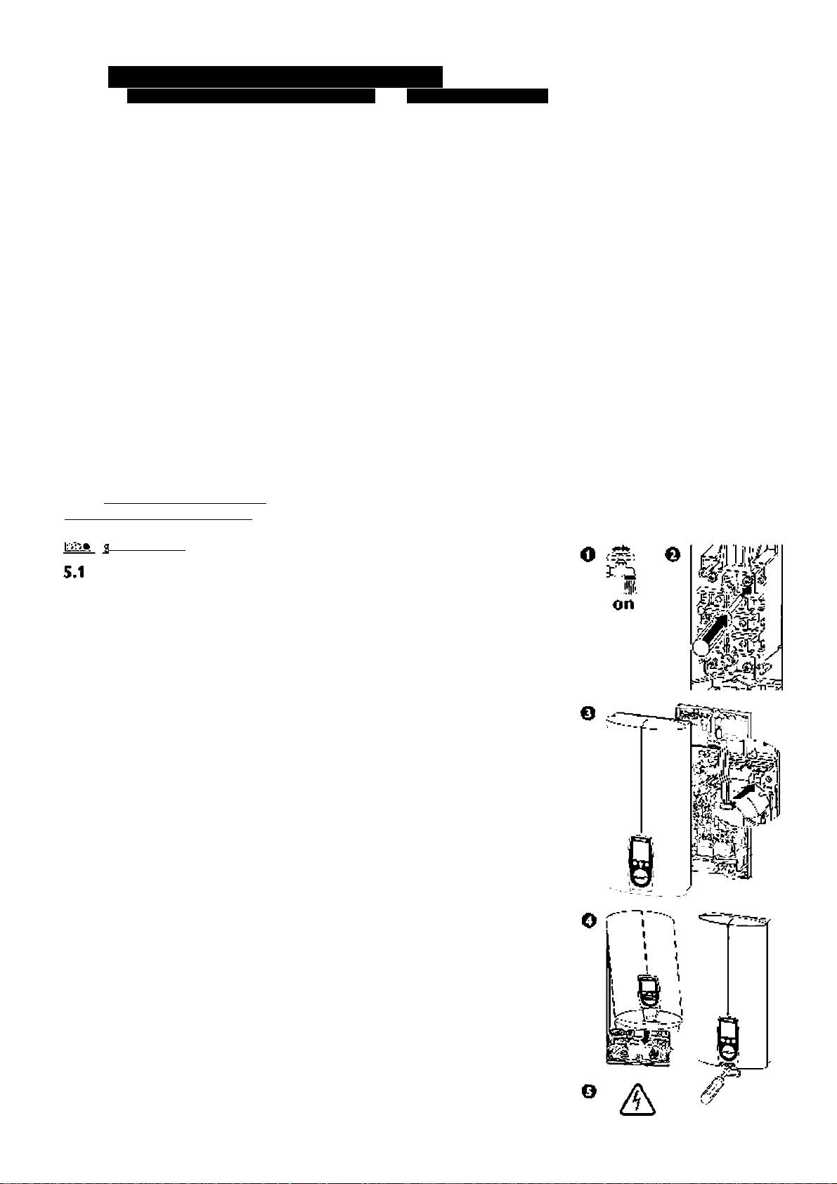
5.10 Initial start-up
(oi'ily l)V A (';jxliilC(l roi'.'rHv'lor)
General installation
information
o Fill and vent chc equipm ent.
Please note: risk of running dryl
The e<]uipm cnc is prepared at the fac*
O pen and close all connected draw-off
eory for standard instaliaeion (see figs.
valves several tim es, until the air has
been purged from the pipew ork and
» ln5ttf.ll*tion a:»ovs a worktop [C] (a).
the equipm ent. seeM .2 Im portant in*
» W ater cc'f.sc:ion. tnfinished w *l s, con
form ation".
oression ftd'j? [G ] (4 *nd 5).
o Activate the safety pressure
» Electr'ea' connect c '. unfi ' is 'ed w a Is. i'
limiter. The DHE...SL! elecuonic
t*:e low e'eq^iprrisrr; a'sa E l6).
comfort is supplied with the safe^
» O irput 21 <V V -brthe D hE 1 ¿^1.^-1 S J.
piessure limiter (AE 3) in stripped
state (press t!ie reset button).
5.2 Place of installation
0 Push set value transducer cable
hjtal the D hE ve'tca'Iy in *ccorc*nce wt'
plug onto the P CB.
Q Cj (a ¿bovs or b be'cw w orkic?) in *
Fit the equipment cap and secure
fx):rn rx)rv Ihc nsk ol irxK ..
with the screw.
5.3 Equipment preparation
o Sw itch on the m ains power.
for installation
Check the instantaneous v/ater
• O pen t'e eq^ipm eir ^;
heater function.
a Pul ihe fl:ip •brvvarc.
e Rem ove the proeeccive film from
b O pen t'e 'kp dc*.v'wa ds.
the user interface.
c R tleast the fxing sc'ews.
d Rtnov« the equiiire't cai.
Equipm ent handover
• K::novf: Ific Iwc-; whII Ijhs:: E •
Expdn t'fe ec^ipm ent fij'ctb' to the ^ser
» l’fx:S '< i lrv.vn 1)0’•• V H|)- n Ih )>.
¡m e •am i ia'isethe user w t' its oper<ttion.
b K::inovo liic whII Ijhs:: ';y |!••ll iij;
Im portant infom tation:
lorw H'xl'-
• M a'<e the ^ser avvare cf possib e c<tngers
» Rsno^e the f.>:in§ togg s E (IS ;.
(scald ng).
» H*nd eve'these inm r'uctions to the user
5.4 5ecurin^i
Securing the mounting
for safekeeping.
bracketTn
• M a k ou: the fxing holes rb ■ the rioun-
tng or<*.cltje: using the institit’c' tenpUte
supplied.
• ?i(:c..r;: Ihf: •nounli' c -.vilh /
on
Stfx;»v> H'-:f I »A-i :)kic-, fn:>l '>u:)|)li:.:(l:
7}

6. Alternative installations for contractors EiectricaJ: unfinished walls - from above, finished walls -
from bolow/above, load circuit breaker; water: finished walls; rotated equipment cap; offset for tiled surface
• I il Ifie IjH-ix-wxl g..i(les'-..ppliex: (cj on.o
Alternative installations are shown in
6.5 Installation of cable
Ifie |)i:)i:i (prxisi l{'!|! and hn'-e O"!-:'! pio::
figures Ш • [Ш.
grommet
«nil |)U'-" .ogt: hi.:r).
fix; i.:r|ui:)r‘(;"l l■■«y 1.:-:: i".> a\ ì.:ìI wl" h rx:jx)-
6.1 Mounting br*acket when
• Push b/ick-v\-M l g. ides (c) c.'to э¡lll'•< w /i I
i- nil iVihlc j/f-nmncl
g^uipment is replaced
eft'e equ’pirer.t unti' it stops.
• Press out t'e C /iole gi'onm et using /i sc'e-
vvdr’v'er (a).
Securing eqtiipm ent
♦ The exist’'•Ц Tiouniing b¡vic<éi сд'- be
W 'S' connectée to 'lex'ble w ^tsrpipe
• Secure the squ orrs't or. the nounti'g
used V rfhe^ lep'^ic r.^ St’eoel Ehron equip-
5y^e Tis the oack w -a I m ust be securec at t's
bracket
ireiit (except ■ D hF'). U se д suitiole
oottorr by rr8?.ns of a' addit'c.t*l screw ' (d).
VV 'en using a 10 O ' 16 m n^ pcp/ve' caole,
g'cniTet in t'-è br.ck vv<*.r.
enla'ge t's hole in t's caole .eron net
• I Un^ I'ic er|u |)rr::i‘.l (ho (b) al .he lop
♦ When rr|)Uri. :g"0 I:' . lur" Iho;'поип-
(r*rijngs B).
/•nil y.ving (i-::wn •;:nl() liie hack whII. I
ting b !îc<tt {a) ' âû* ( ego "DKP't. rnee
wef:s o’Tfie r h:> g..i(les mij-J gri:) n c '"i:
• l\iv ihc i xl;!!: ¡/-xrmr-cl ovx: " .hi: :)(:wcr
ю л'д ds the 'e<*.den ¡ind то-.е the 1Ьгед-
r/d;-:: (b.'ivJH'lHlkrn/ii(J), M o h::i:./i(k
' :-/«k-vV«ll gu ilc'- /tfixi loe-i ’"I-:: l"i:-ri.
ced st.d (b' to ihe uppe-' r'-. corner
WrtI (cj rt‘'il sriH:) |:IhìX: {d).
♦ When ni|)Uri"g Ihi'il :wly :ir|ui:)n'c' l.
6.6 Soldered fitting
US!.: i!..i holes or ч'Л'1 |)1..^ч (с) .г.:
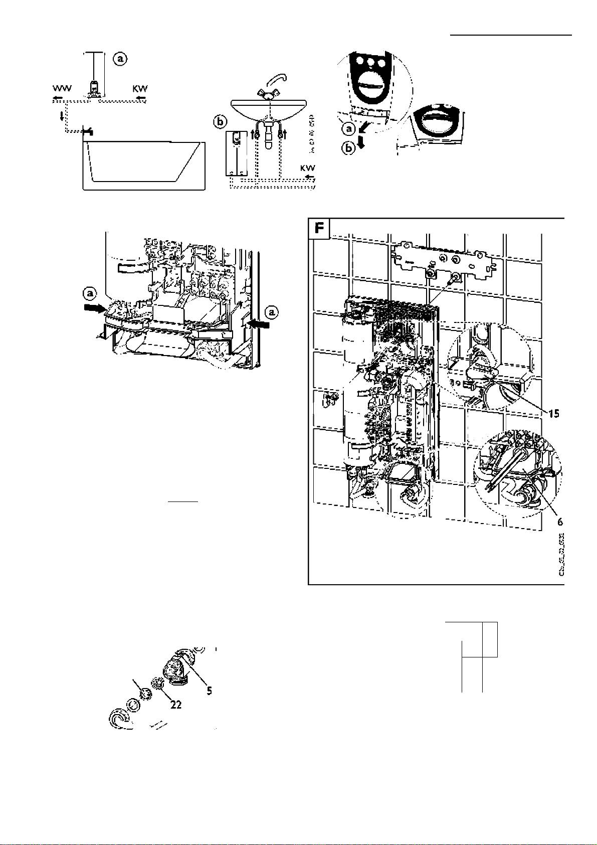
6.6 Priority control B
- finished walls
Чл'игх; Ihc nounli огжке ч..|)|! icd.
When ..\c(l in f onju-'x-l'o" wilfi ctlicf <:!<:< Iri-
Using the special acccssor/B (a).part no.
(hI (:<'iji|:‘ri(:nl, ::.g.(:l(:cl4c ’■lor-rjic "ivi ::rx. ..sc
see “10. Special accessories", it is possible
6.2 Electrical connection
hi: k:.?il rifx'..i l:c:/ikcr
to provide a screw connection w ith the
-finished walls
a I C/iil i.irx...i l.:-:.Vikcr :W<; ”10. Special ac
custom er's 12 m m copper pipes.
♦ C ^t O ' m ake an ooeni'g for the pc'/ve'
cessories").
• Install pa'te o'the >psda accesso'y.
caole in the back w ¿ll anc ec^ipm err; c<.p
b C'on.fX)! "/d: !: .o .he of Ihe
• Sol(:::i* liic in'-c-1 f: h:: (•:'!|::)cr :)i|>::>.
(see E *o' pois ble locations for openings.
f: I he er I.. pm: :n (< : : :le< I fir s. O'Hg: : f le-
• PiaIi hvirk--.V/i’l-)asi: ufi(ii:rTicHl" .hi:
♦ The protection level cha'ges to I? 24
V/il-vx: ronnex li::ri pi:)::'^ /irixi vap irilx) Ihx:
(spl«*.sh-p cof) fc' elecric*.! cc"ec:ioii on
c C'on.fX)! i-tvlrti - (>:)envwhensv/i.ffii"ji
top of the bick ywill.
•In’shec W ill Is.
t'e D HE... SU on.
Accentiorv.
• Sc'ew e connect c ' p ’pes to the ec uip ■
The load breaker trips as soon as the
The equ’orte'tType pl«*.te rt.-s: be rr:<*.r-
.m em .
DH E ...S U starts.
kec as fol cw s in ballpc m pe':
O nl/ connect the load circuit breaker to the
Attention:
Cxss t"o.,.eh I? 25 and рл a cross i'
centre phase of the equipm ent term inals
Nets the in'onration in "6.7 C om pression
the oox IP 24.
{m ains pow er).
fitting^ — finished w ü IIs ”:
• I x]iji|)inx:ril r/i|;. x;x|u prr::r.' I;arkw/il H"xi
6.3 Electrical connection -
6.7 Compression fittings
x:x‘,iji|:‘nx:ril Ixini/i“usl l;x: prx::)/tfx:x! x>r
from above T]
lirs ¡n>-lH lHrf: - iv::r::'!xi.
♦ C wt Д hole for tte povve ■ c<*.ble in Lte сд-
- finished walls
• Equipm ent fxing.
be s'C -nm et
Sdcbcl E itron pressure valve (finished
walls)
• C ap in5t?.l ¿tion.
♦ .^.ih tte tenr 1пд1 st b up.v<tids roir
be cf/i\ 'or th s oresi n the 5пдо-1п ttb (a)
W K MD orW BM D B
/I'd sol/ite 1 'e ter.’nin«*.! strio.
{p<ti~ no. see "10-S pecial accessories")
6.9 Installation of back-wall
Accentiorv.
• Rt t'è w :ïter oLg G 'A w’t' g<tskets (a)
base
V.stal f.exib'e wires u'derthe C/iole gutóe
(p/i t of Ihe s:!inc<ti'd delivery cf Stiebe
With connection fittings for finished walls,
;Ъ)!
Eitron oressui'e Viilves for finished w dls).
the back-wall base can also be fitted after
Sii/io üie tern iiiil si rip into plice /itt'e
T-.V O w /iter pLgs (special accessory set'
the val>№s have been fitted :
too (c).
(see "10. Special accessories"! r.i'e re-
• C u Ihc ‘yM.<-\Wr.\\ h/iH: (3) ^hxwn in
qui. ed fcri'iit: pcity press, re vdves.
Ihx: ilirt^f/ii“ (a).
• HU"i.: v«l\‘x;i:.
6.4 Rotated equipment cap
• Inse't t'è linlis :(b t c it the extrr. ’tern
The equipm ent cap can be rotated for
• Pus' the :>3C i.-v\'i.ll t<.>e oelc'/vthe valve
creered) fiion t'e br.ck into the centre
under*w orktop installation [M ] :
connecicn oipes ¿nd sn<.p r i'to the
¿¡irt
♦ P'sss in t's s'ap ' tat- to rem ove the
bacr.-w al top.
• C u'de tte centre part underneath the
и5е':леТгсе (a) fron t's equipm ent
• Scre/v the co"sc:ion oipes to the squio-
oipes, ous' up and fit v\- t' the oae’e w '<.ll
cao.
ne't
oase.
♦ -Rotate the sqiiiore't cap (b) ('otthe
• I ft tlix; hHx k-W/il hviÿx; !•:: V :.: hvir.k w«!.
ec./ipm ent). Insert the лег inter ace and
Prepare the equipm ent cap for this installa*
I "i: hvif k-v.-H I •)Hvi: fr..v. h-:: ''x:; ijfx:xl wi.h
loci, all snao in t?.bs i'to о1гсе.
tion E:
/in Hilxl rx>"/il \x-:w (c).
Attention:
• P Crtk f:-.:l I":: hush -;nf>rk-()ij i (a) in h-e
• I ft U ix; vH Vi.: •: ••: :f i • x;-:;! x >• ; | : i| )x;.s . x > ■’Jk:
Do 'ct insU ll a ./>er interace w ith dana-
i.:r|ui:)ive"l r a:> i.-'i.:/«fily.il nece-ÿ^H-y us:.: <i
x:x‘,iji|:‘fix:fil I lli"j;'-.
ged snap- n taos.
file.
♦ ?. sh set \due t vi'iduce ■ ctble pLg onto
• K-W < oij. Ifie li;)i h-e <h:) guides
6.10 Offset installation for tiled
the PC o (see О Initial scarc-up").
Su|>:)l i.:il (b). II I"!.: v'rk'x; ror.net Jon :)i|)i.:^
surfaces
♦ ln"j> Ific :::’|iji:)i'ic"l Г/«|>{Ь) н11"!:1х:1-
¡ire sightly oflse:.the C /ii g.ides (b! c*.n
VV rer.the squiore't is *r:sd onto * tiled sur
.o ri wk: ..|) in r.: |)-::j:ri()n cn l"<;
be .sed w hliou. k'ccdng oir ihe lips. In
face ( [B] m ax 2C r m ). the to.e§ e
bctck vvd. P ush 1 '& otp forw /i'ds ¡ind
t'is C /ise.t'e br.ck-w /i1 guides (c) ¡ire not
( E 1S; 'nrti*lly aciuststhe •v\-*ll cle<.ra'ce a'd
Ьг.скл-д ds tc ens. e cor. ec: sfetting of
usec!-
t'e' secures the ec.. ip m ent..
the sur'c-'ding br.ck-w /ill g/isket.
• S'lp t'e c<*.p gukes into the sh knock-
♦ S(fx:w d(Av;: hi: (:<‘..i|:'ricrrt {Vii).
o./t5 i' the equipne-'t cap.
iO

STIEBEL ELTRON
7« Specification and application areas for contractors
7*1 Specification (details listed on (he i/pc plate apply)
Typ
DH EieS Li 25A
DH Eie/21i‘24 SU
DH E 27 SLi
electronic
electronic
electronic
com fort
com fort
com fort
Ka't ntn'ibè'
227492
227493
227494
Rated po'A 'er
kW
18
21 24
27
htted arreit
A
26
29 31 35
59
l-Lse prc:s<:tici
A
25
32 32 35
40
</>
Cj:puca;i 5e selected
no
yes yes yes
no
wt
Krasst'e loss ^
r'K a (b?.r) f /ni:!
0,D^ (0,4) j>,2
V.04 (C .^) 5.2 0.05 ;0,6) ; 6.0 0.08 (C .3)
«Ì
ai ;-:.0)//V
co
Ccp^cr/
0.41 '
l/pe
cicsed
Px'JeU cvci pr.:ssi I i:
' N Pa nC :>dij
'/.•'ci^hL
4.5 h-
Pro.ixlici c<'.ss /12 pe.- D K CN ’jfXilS
1
PrXi.ixlic i ri'odc Ki .¡Cr IN (¡('529
IP
25 (P 2^ r.L Che. ied co!: iC;lon - i i- sLec w/i! sj
Test inK fVs
■ici: y iil.r<'.lini:
'/.•■«ilCi i.i;nn;x.lio'i PJxLerllfil lliroa'j)
G
□ix.irioi! C0hri:( :ic i
3.'PC - 4C OV
B/jiC >Y e hcrd''^ s/S.0ri
sce e''a.;lci Cfi iCf.Lon rirx:<'.s
Applica .icriS
waler'
>ylh !o'.v I -ni^sc/iie ìa^cK <vid wi.l' lii'ic-&ix'.b cotiLuiU
Cdc \va.;:r rei .criMcralLii:
n ax. 55 ”C
P.V:^e of for hpcüi i. d;x.lrioi
ras r^x&'coiducvr/
sccTi,:/:: 3
FIcv/ vi;ijfi o ..O :"
>2.5 .•'ni i
Libie
** V.ilues ’iV|)^i^s..r;i ^p|:l/ lor i*r"in'..Ti ilo‘/v p cà^u::ì ;ì(X’f:-eli"^ lo
I3I\ lo-.v vx)l..-ne ioi henli- c Lorn 10 "C : lo W J 'C (.^^9 .50 K;.
O n the basis of DIN 1988 Part 3.Ta:)le 1. pressure loss o"0/ M P <. (1 b?.r) is
reconrnencsd w t' “c ihs cirrs'sion n;? ofths pipe nsTvvork,
7*1 Area of application
Area of application for instantaneous w ater heaters, related to the specific electrical resistance of the w ater/specific electrical eonduecivity.
De:ni s as
Ranges of use for different references tem peratures
Ncrrrss detai s
atlS X irt.20 "C
Specific electricr.! resistance
2 900 Q cm 2 600 fìcm
corresponding to
Specific electrical conductivity
<111 m S/m s 125 m S/m
< 1110 pS fcm < 1250 pS fern
IhHc y,
^ The values for the spacric electrical 'esistcnce o- electrical cc'-ducrivrv .'especl valy are to oe date: r ined s'- a reg c'-al!y civergeiT bas«.
Hi (ii"cfx:fil U;rnpcf'.i iJfx:s I r’uvl h<; '.iken if Ho H :.f oun i" Jk: 4bi:i.iiSfK:n».
11

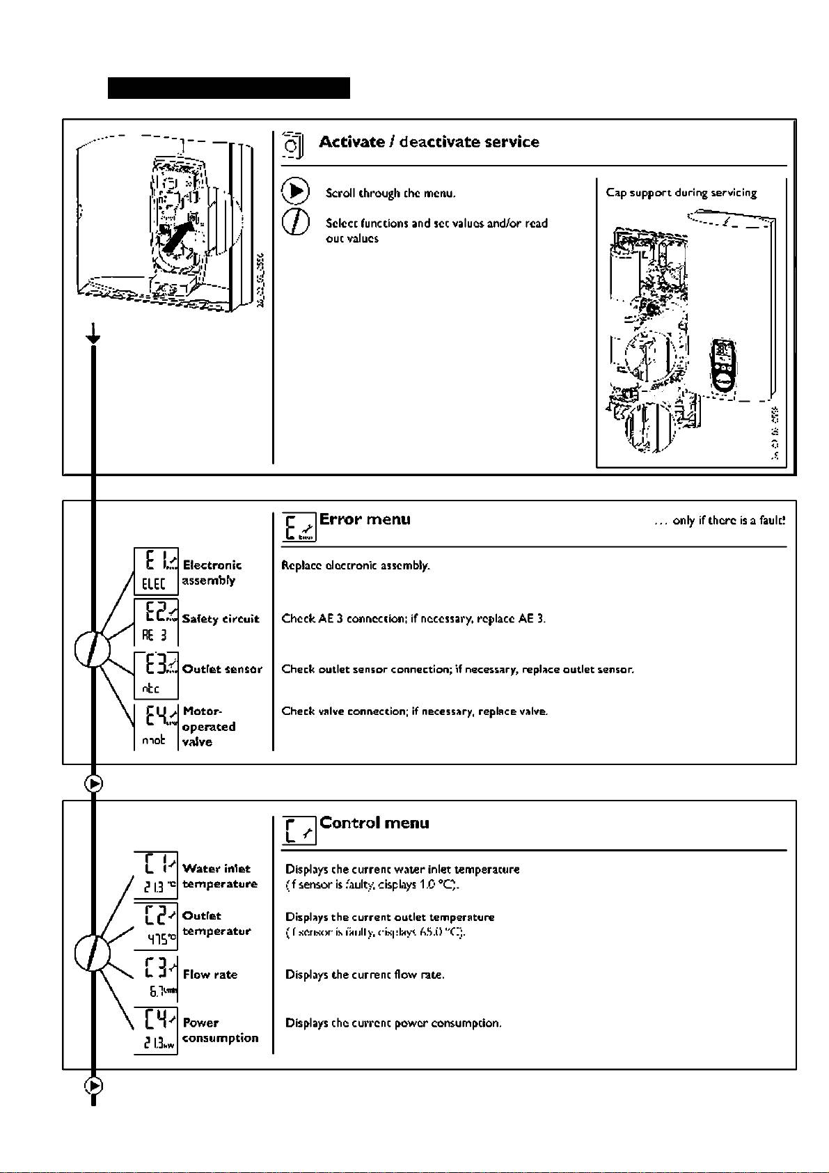
S.Troubleshooting by the user and the contractor
Störung
Ursache
Behebung
Flcr/v r*t« zoo la*’
EC O m ode 's activatsd (anc I n t is sst a: *
User: D8?.c:i-v*t8 E CO i/.tec8SK .r>-.*d^^5t '8vsl).
Icvnl)
Sho*er hfcic/pe'colsitoi'i scA sd .0
User: Descale a'-d :epl«tce 'f neoes5<trv.
Contirii'-etiori
Contractor: C lea^ strai'-et
M eter cosratee v<Jve de'eöve
Com neter: T8st 'v-alv8 a'd 'eolace if necessa'y.
Cc"l nijo..» Error (lis|in/ cn
I Aully 'iCrive .•'l’CB
C'on fa :-l ;:i • A -alyxc laull !.. l--c ¡-- .he snr-vi;'n m odi: (c
fX)r
n :vÌM.o
•ncnij).
F<*ulty co'nnum icr.tion bet*een . ser inter-acs
Contraotor Test.ser inter'ace ¡ind oon'-eotng c^ibe.
and conti'ols
S'o -C D c'splay
N0 vohage
User: Test .^ser interace and ccn.teot'n§ cab 8.
Q:nnc-:;l n^ .0 iiv.';^'"lc-i«ce locs:.i
Con
iN ii!^ in i.onnccli cahlc-
A£3 has tripoed
Contraotor- SoK-e tlie eluse o'tlie fault Ki^se ^etting sy
'Sten
0' - nr. in order to <tvo d o-i«r-heat ng t- 'ii c,
t =igdn
.AE 3 (checi. for coTect connection of STB •
sa'ety
thernal c^to'Jt-).
lauliyPC n
Con fa :-l-:':i • InsI Ihc l'fIR arie rx;|ilare ¡"¡-nrc'-sar-y
HeAtór does not svv'tc'- on / '‘c
hesitrg svften' •'a.bv
Contraotor- Test '-ette- a'-d 'epl«tce f neoessa-y.
hot wAter
DFE 'a. bv or not p u||ged l'
Contraotor- Check DEE connect’c'-:c'-eok flow -rcte m è!is- -e-
m ent the seiv cs m ode.
Error •"'iv:)lHy h:)|k:h v only
O r ic |]hH 't(! dow n
Usnr: C\v'.i k iij’-cs/'dCn fiuto box).
•.vhcn W« «iifig (! H-.vn nl
I aulì n Ihr: tH icly nicr IrxH^io:
Con fHi lof: ! \ ir I .Al :r i • :< l'ni^ : af > : - < - n: k A 'T
'W ate' i.'i ettem persTiuie > 55
Contraotor. R educe lem persituie oft'-e -w :iter supoly
m snTbis't cole w ater
VV sIbsss 'unction activated
User: De*ctiv*t8 w elbess funaion.
ß icl irilcr- u|:-l c" oi l'c-.v h Ic
I r|iii:)r'-c"l aiilorvalirn’ly nyJw Iv -.vhcn l••(: n is a v..iiricfil iirrw
hIc.
A'- s&'-sor '& act£ (colo w ater fc' ¡ipprox
Equbire'-t ¡lutoir-etica ly resti'ts after a del«*.y.
Wjn.S
vM ien the ec.ip'nent s repaVed.
he factc'y-cc'-fgurec le«*.d eirsinge'nent 'nust be 'es:o-ed. M «*.ins c<*.bles n'-n '•oi touct extia- cw--i-oltige c<*.bles.
V
STIEBEL ELTRON
9« Service mode for contractors
</>
wt
JS
STIEBEL ELTRON
10. special accessories
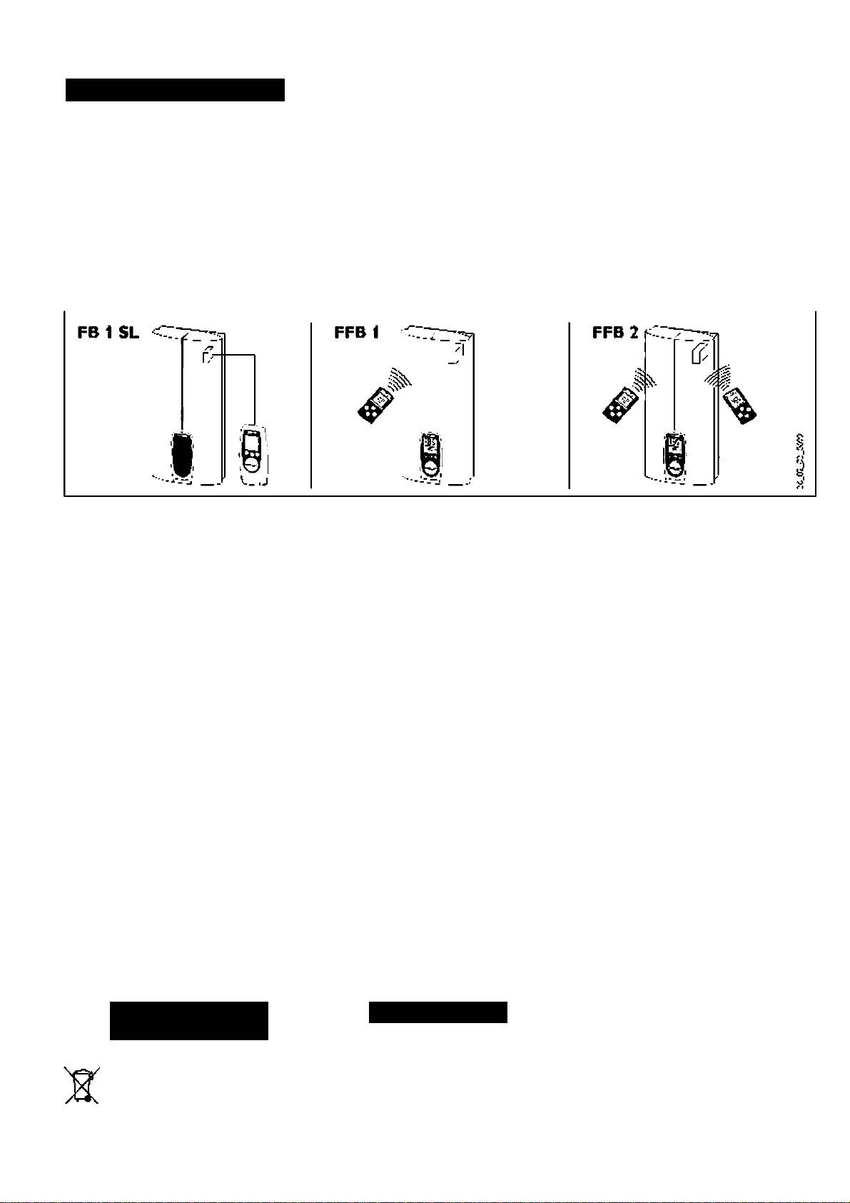
Rem ote controls for D HE...5LÍ
FFB 1 SL - W ireless rem ote control
FFB 2 5L -W ireless rem ote control
• FB 1 5L -W ired rem ote control
Part no. 22 24 19
P^rt no. 22 33 40
Part no. 22 13 33
Control from two locations.
W ireless rem ote control unit as extensi
O peration only from rem ete ccntrell!
I;:c •.vifx:':'S'-rxin'rilf; rrvl r: l 'Í1í>l orrt-
on of die FFB1 SL.
I l•.!.í w i i.iil :.vno i.i (.iifiU x)! FB 1 5L
hov l;:(; (.on,rx)l ;il [-c )l I ... ?;i i -x)!;: i[
“Iie w reless - enote control FFB 2 SL
•;\>:ír.ílc(: u'-ini^ :íxI-h-Icw vc
I ho n|)|:IÍH"! c ^n:l vi« wnilos •:rn()
eiu'oles n sv'& ten extension x^ith up "c
IV:i lc( I ! o‘rirnuni(Viii()n ‘i ^uar anlcoil up I-::
(•::rilrx)l. If•^n'- riisx'c" ’rxx;..:vi y '’ll 1/,
5X xvire ess use- rte-feces.T-nnsnsso-
(••:r "C ( lirv lc"g ho"1H ‘ri. C 'oriirx)!
hi(r-:ii ionH'.rwigc rt:)|)rx)x.7f: 71.
•req.e^cy Sóó.3 I'^hz. oiciiecticnal. iri-ge
Teleplione line, type J-Y Y 2x2x0.6 (vvi-
S.-jriCrtfx: (l(; vATf
•iporox.
'25.71.
'rK U-» li<‘ '•(■•:í:íi'.ifi¿:.
ííKxiivor •n-:«l..':í. witxílcs*- u'-c.* inla Ih:
Stiiidzrd del very:
to
A: (csxory;: onnxx li-::n Tuxl-.h. r/xl rn(>..n
H"il Vv^ll fxí •ji;:c-:
W ire ess use- hterfece ¿nd w dl retai-er.
¿nd use.' rterfece.
Tw o-handle pressure valves
7 X (•;:fn|)rx:s-%i;:n ii I'nj^ y>" k I.Sfvri. p
I ; : (x |i 11 >r r.: :n \ y 70 r v • r i < i( r-, v- ",v-. n h
• K itchen valveW K M D
I^ixkcl’-
:'r>- r i| : i rxx I r: ii: : wH I cr >nrxx I i< >r i.
Part no. 22 24 37
Com pression fitting - plastic pipe;
G as wacen>hcatcr replacem ent sec
• B ath valve W BM D
Part no. 22 23 81
Part no. 22 O S 10
Part no. 22 24 38
2 X w ater pLg C >i”.
cons sting 0’1
- 2 X corrpiession frt'ng* '/z"' x 16 m rr
-nk-ersd nounting T<*.ire (see p<*.r no.
installation accessories
(Viega:S a'fx Plus or Sanix Fosfe', olus
22 02 91 for spediczt!o'^
• Under>worktop sec - unfinished
gaskets
obe be-ds fc' i-stal ation <" existing gas
walls
Universal mounting frame
w*te " eater cc.t'eccio's (cold w ater
Pare no. 07 05 65
Part no. 22 02 91
ler a'd 'ct w*te'right).
C'onnxx li;:ns or ll••¡'•;:(:(^ v.-H I'-.Ci Vf>". lop
censi'-r"^
Load circuit breaker LR 1-A
• Set 2x water plugs G Vt
- fv(:::"l i-H-ric --.v l -
Part no. 00 17 86
Part no. 07 43 26
- dcdi iral •7v’n--^
rriorly cxilrx)! cl ••:: )l II ...SI i chi rxxik
Requi-ed w t- third part-/ oiessure vaves
ii'v i ol n ri ix:.-
iorikx l kx--•;i-nijllH--:x:.:s cpc'-jlkxi cl
if^a).
•.v:::v. I he (;(]iji:)iricril \)w<. v.-hII -inxi h::
::l(Xlnr hcHici >. I oi ronrxx lion r:I
i 's hI H.ion '-a-'HII.
No.:::
Is 11-Ai<;(;(^.
il l c -^hlcs liie ::lerlrrH' ronnex lir:-- r:
No. rxtcuirxtc briili(:'-j::l I l.rx)i-. vilvx:s
i:<; fx)ij i.:il ever un’kiishexl -»v-il v •. h- y
WK'^D ind'Wir^n.
Accessories for operation of a
p-::i--| hch/'il l"(: cf|u prr.::n . i--cfx:-s'-:r'i
• installation set for finished w alls
DH E ...S Li w ith pre-heated w ater
.h;: ccuip-ncril d::plh •)/ 'fOrnrv H--<i
Solder fitting - copper pipe:
ZTA 3/4 - central tiierrncstatic valve
fxxi.I -:: p-oUx lion level r: IP 74
Part no. 07 4019C Q |a)
P^rt no. 07 38 64
(s:)lH'ih-|
coriipTsni?;
By Hi 1(1'"^ col: I w-. :vvÌH h •jypHs'- pi:x:. I-.::
Offset installation - unfinished walls
2 X v\-3te-plng C >i".
rcnlr^l l••(:•n'•:wU ir --/hv:: i--^.nihil in'-'ic-
Part no. 22 02 90
2x .,'ion >i” w V i'seii for soles'
il'« :.:ly lh<; v^orn;;:.: wnlcr r.vlirxk;;
consist 'g of
fitti'g 0 '2rrn.
gii«rH"l(x;s Ihnl l••(: ou Ic Uxv:x:r«l..-:: o '
- universal rrou't 'g f'aTie (see oaii 'c.
Ó 0 is not exceeced.
Cem pression fitting - copper pipe:
22 02 9'i fc'soecification).
Part no. 22 23 80
- p pe oends *or vs'cica cisolacerientof
2X w ate-pugG 'A".
11« Environment
12« Guarantee
and recycling
Recycling of obselete appliances
For guarantees olease -efe-to the oespet
/\ The installation, electrical connection
App'ia'ces w it' this l?.be! nr.,>t net be
t!ve terns .ind ccnchions of s-ppy for
ci^and first operation of this appliance
ds^osed off w ith tie gene.'al w aste.
ycu' countiy
should be carried out by a qi-alified installer.
T'ey m ust :>e co'lected separate v a'd
d'sposed o?*ccorcingtc local -egulat o's.
The com pany does net accept liability for
feilure of any goods supplied w hich accor*
dance w ith the m anufacturer's instructions.

%

STIEBEL ELTRON
Sommaire
1 Instrucción; d'utilisacion pour l'ucN isateur «c le profe;;ionnel42
1.1 l3:i«T |:ron tic rH|i:)H-dl
__________________________________________
4V'
1.*/' i'oncui ( v ^ik Ic
______________________________
4/'
1.2 .=i,tcoiTr<-.ndation pou' It régligt du rob'net t^enтcst-tiqut 42
l.'l C onsigne de »éc^rrtë _ _ 12
l.h li;ir‘>ii :|u:^ i ri:>or.Hnl<:________________________________ 4/
1 .é> Q ue fil l e tn cas de panne?___________________42
1.7 E'-.retie'-et nartena^ce
.........................................................
12
1.& ln;t'uc:ic'’5 d ^lüivation s: de rr.oncaee
..............................
12
2 L'utiliâiitioii en quelques m ots pour l'utilisateur et
le proicssioniicl_____________________________________43
1. ' D'u'ieul cou? c'csil....................................... 13
/.7 en Ih U :in:)('::nl..ix:
_________________________
4’?
7. s Inivriifi.-: c 'h Ih -.t k :
_________________________________
4'^
v>
14 Fonedo“ ECO
____________________________________
43
<
3 Réglage des fonctions de confort pour l'utilisateuc ec
O*
la profesâionnal___________________________________44
<c
oc
2. ' Te. che» de fonctions avec poss’b l'cé ce -églase
_
44
2.2 D tuxiè.ne aï chr.ge pou- infoi 'nr.don_________________44
2.5 R ée 3gs ces fonction; ce cc'ifcr.. .
__
____
_
_ .11
4 Instructions de m ontage pour le professionnel
________
47
4.1 D tscr'pt'on________________________________________47
1.2 R erai’ques im pc-Tia-tes....................................................... 17
1.5 N orres S C cispositions
........................................................
17
5 M ontage standard pour le professionnel _____________48
S.'i Inst^ucrion; ¿«é'-árales de rc'-ca^e
__________________
4s
5.2 En?l<'.cene‘-. derr.ontr.ge
..................................................
13
b. s IW ::)H ra i:i:' d.. m onlrti^c :1c l«|:pHrt:1
________________
4H
5.4 Fixât on ce a p :icue de susptn;ion __________________4S
5.3 Coupt eu c-lole dt niccc-dtrrtnt_______________________-S
5.6 M ontage de l'a^parsi' ______________________________15
b..'' Rw : r:it::urc:nl In-ci^uliciic
___________________________
“b
5.8 R accoicéirent élecilque_____________________________-5
5.5 Ternne-lenr.onti.ge _ .. _ .._ ,._.15
5.'i0 Pren'ére m ise en ;ervice_. _ .15
6 Autres m odes de m ontage pour le professionitel
______
49
6.1 .Arnr.cure ce suspers'on eii C :ïs de 'em placeirent
ce 'aoparei ............................................................................. ^9
6.7 ltHi;r.r:ix::.';ircfil :3lc;r.l ir|ii:.': - r.|):w c"l__________________^5
(1.2 R Hcr.r:rx::.';ircnl :3l(;f.l ir|u:.'; - c iî liriul
_________________
^5
Ó .4 C apoTC è 'aoperei tourné
___________________________
-5
6.5 M ontage de la gaine de câblage
......................................
^5
(‘«.6 R f: )iiicllcr:is H :)|:rtr:inlcs
_____________________________
“5
6.7 R accoiceirent soudé r.ppare'^':«
_____________________
45
6.8 M ontage de la ?a^ie arrière 'n'érie.,re
________________
•'5
6.5 M ontage avec 5r,i l e ce faïence
____________________
■'5
7 Caractéristiques techniques et dom aines d'utilisation
pour le prtiiessiofinci
______________________________
SO
7.1 C ar^ctér'sdcue; techn q„es. _ .50
7.7 :hil r’-a.in -
________________________________
.5C'
B Dépannage par l'utilisateur et par le professionnel
_____
51
9 M ode S ervice aprês-vcncc pour le professionnel
_____
S2
10 Accessoires hors*séne
____________________________
S4
11 Environm ent et recyclage
_________________________
54
12 G arantie
________________________________________
^54
в
ÆV
ib
D
STIEBEL ELTROri
..
.......
t
t '
t >
t I
t •
t ■
W W
®
v>
h-l
<
<-►
z
•«
0£
4« Brilli IC-
„ Щ0Г
-------
--•? -Ci'
i '•Vv-I.
_________
J
3 SP
®
H
I»
lüO nn
1 _
1
30 nm
¡ 1 1
.Щг
i LJ
í —
'Ü V¿^
Г"И
II
i
23
-----------
-
....
I
----
1' li
L1V L2> L34
a
lì
ttl
........
"■ ■
L fe L
I ■. I
.
..............
.......
: дщщ
3/PE - 400V
i’)