Delonghi PGX 664 GHI – страница 2
Инструкция к Плите Delonghi PGX 664 GHI
21
COOKING ADVICE
GRILLING AND “AU GRATIN”
Grilling may be done without the roasting
jack on position
of the switch,
STERILIZATION
because the hot air completely envelops
Sterilization of foods to be conserved, in
the food that is to be cooked.
full and hermetically sealed jars, is done
Set the thermostat to position 175 °C
in the following way:
and after having preheated the oven,
simply place the food on the rack.
a. Set the switch to position
Close the door and let the oven operate
b. Set the thermostat knob to position
with the thermostat on position between
175 °C and preheat the oven.
50 and 175 °C, until grilling is done.
c. Fill the dripping pan with hot water.
Adding a few dabs of butter before the
d. Set the jars onto the dripping pan
end of the cooking time gives the golden
making sure they do not touch each
“au gratin” effect.
Note: It is recommended
other and the door and set the ther-
that you do not grill for longer than 30
mostat knob to position 130 °C.
minutes at any one time.
When sterilization has begun, that is,
ATTENTION: the oven door becomes
when the contents of the jars start to
very hot during operation.
bubble, turn off the oven and let cool.
Keep children away.
REGENERATION
TRADITIONAL GRILLING
Set the switch to position and the
Turn on the grill, as explained in the pre-
thermostat knob to position 150° C.
ceding paragraphs and let the oven pre-
Bread becomes fragrant again if wet with
heat for about 5 minutes with the door
a few drops of water and put into the
closed.
oven for about 10 minutes at the highest
Introduce the food to be cooked, posi-
temperature.
tioning the rack as close to the grill as
possible.
The dripping pan should be placed
under the rack to catch the cooking juic-
es and fats.
Grilling with the oven door closed.
Grilling with the oven door closed and
ROASTING
do not for longer than 30 minutes at
To obtain classical roasting, it is neces-
any one time.
sary to remember:
Attention: the oven door becomes
– that it is advisable to maintain a tem-
very hot during operation.
perature between 180 and 200 °C.
Keep children away.
– that the cooking time depends on the
quantity and the type of foods.
22
SIMULTANEOUS COOKING OF
OVEN COOKING
DIFFERENT FOODS
Before introducing the food, preheat the
oven to the desired temperature.
With the function selector in position
For a correct preheating operation, it is
the ventilated oven allows you to
advisable to remove the tray from the
cook different types of food at the same
oven and introduce it together with the
time.
food, when the oven has reached the
Fish, cakes and meat can be cooked
desired temperature.
together without the smells and flavours
Check the cooking time and turn off the
mixing.
oven 5 minutes before the theoretical
The only precautions required are the
time to recuperate the stored heat.
following:
– The cooking temperatures must be
as close as possible with a maximum
COOKING EXAMPLES
difference of 20° - 25°C between the
Temperatures and times are approximate
different foods.
as they vary depending on the quality
– Different dishes must be placed in the
and amount of food.
oven at different times according to the
Remember to use ovenproof dishes and
cooking time required for each one.
to adjust the oven temperature during
This type of cooking obviously pro-
cooking if necessary.
vides a considerable saving on time
and energy.
DISHES TEMPERATURE
Lasagne 220°
Baked pasta 220°
Pizza 225°
Creole rice 225°
Baked onions 190°
Spinach crêpes 185°
Potatoes baked in milk 185°
Stuffed tomatoes 180°
Cheese soufflé 170°
Roast veal 180°
Grilled veal chops 210°
Chicken breasts with tomato 180°
Grilled chicken - roast chicken 190°
Veal loaf 175°
Roast beef 170°
Fillet of sole 175°
Aromatic hake 170°
Beignets 160°
Ring cake 150°
Plum tart 170°
Jam tartlets 160°
Sponge cake 170°
Sweet dough 160°
Sweet puffs 170°
Plain sponge cake 170°
23
MINUTE COUNTER
5
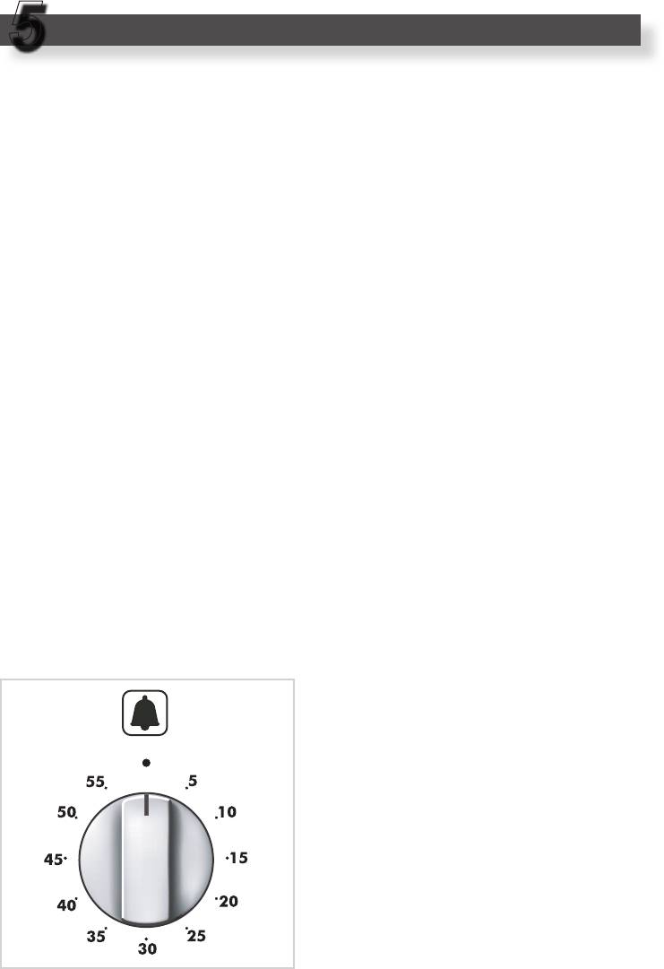
MINUTE COUNTER
(Fig. 5.1)
The minute counter is a timed acoustic
warning device which can be set for a
maximum of 60 minutes.
The knob (Fig. 5.1) must be rotated
clockwise as far as the 60 minute posi-
tion and then set to the required time by
rotating it anticlockwise.
Fig. 5.1
24
CLEANING AND MAINTENANCE
6
GENERAL ADVICE
– Before any operation of cleaning
and maintenance disconnect the
appliance from the electrical net-
work.
R
– When the appliance is not being used,
D
it is advisable to keep the gas tap
closed.
– Every now and then check to make
sure that the flexible tube that connects
S
the gas line or the gas cylinder to the
appliance is in perfect condition and
eventually substitute it if it shows signs
of wearing or damage.
Fig. 6.1
– Do not use cleaning products with a
chlorine or acidic base.
– If a gas tap jams, do not try to force
it. Seek technical assistance.
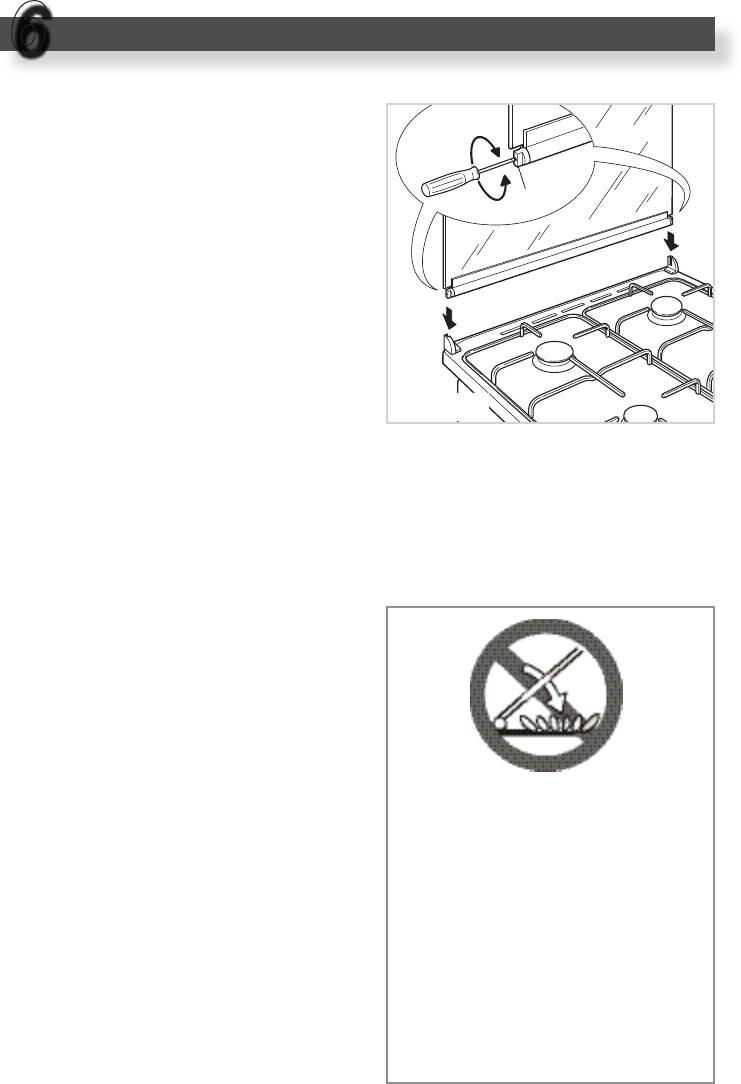
GLASS LID
(Models: TG.. 664 GHI,TEM.. 664 GHI)
For cleaning purposes, the lid can be
easily removed upwards once taken to
the upright position.
Should the hinges slip off, replace them
in their housing being careful that:
– The right housing must receive the
hinge marked “D” while the left hous-
Do not shut lid when
ing must receive the hinge marked “S”
burner alight.
(Fig. 6.1).
ATTENTION
REGULATING OF THE
- Do not lower the glass lid when
BALANCE
burners are still hot or when the
Lower the lid and check the correct bal-
oven is working or still hot.
ance. While opened at 45° it should
- Do not lay on the glass lid hot
hang up.
pans and heavy kitchen utensils.
The springs of the hinges can be adjust-
ed if necessary by turning the screws
- Dry off any liquid which may have
“R” clockwise (fig. 6.1).
spilt on the cover before opening
it.

25
ENAMELLED PARTS
STAINLESS STEEL SURFACES
(Model: PG.. 664 GGHI)
All the enamelled parts must be cleaned
with a sponge and soapy water or other
non-abrasive products.
CAUTION
Dry preferably with a soft cloth.
The stainless steel front panels on this
cooker (facia, oven door, drawer or
Acidic substances like lemon juice,
storage compartment) are protected by
tomato sauce, vinegar etc. can damage
a finger-print proof lacquer.
the enamel if left too long.
To avoid damaging this lacquer, do not
Do not use a steam cleaner because the
clean the stainless steel with abrasive
moisture can get into the appliance thus
cleaners or abrasive cloths or scouring
make it unsafe.
pads.
ONLY SOAP/WARM WATER MUST BE
USED TO CLEAN THE STAINLESS
STEEL SURFACES.
STAINLESS STEEL,
GAS TAPS
ALUMINIUM PARTS AND SILK-
In the event of operating faults in the gas
SCREEN PRINTED SURFACES
taps, call the Service Department.
Clean using an appropriate product.
Always dry thoroughly.
IMPORTANT: these parts must be
cleaned very carefully to avoid scratching
and abrasion. You are advised to use a
soft cloth and neutral soap.
REPLACING THE OVEN LIGHT
BULB
CAUTION:
Do not use abrasive substances or
Disconnect the cooker from the
non-neutral detergents.
electrical network.
When the oven is cool unscrew and
Note: Regular use could yellow the
replace the bulb with another one
surfaces around the burners (due to
resistant to high temperatures (300°C),
oxidation of the surface of the stain-
voltage 230 V (50 Hz), 15 W, E14.
less steel) because of the high flame
temperature.
Do not use a steam cleaner
because the moisture can get into
the appliance thus make it unsafe.
26
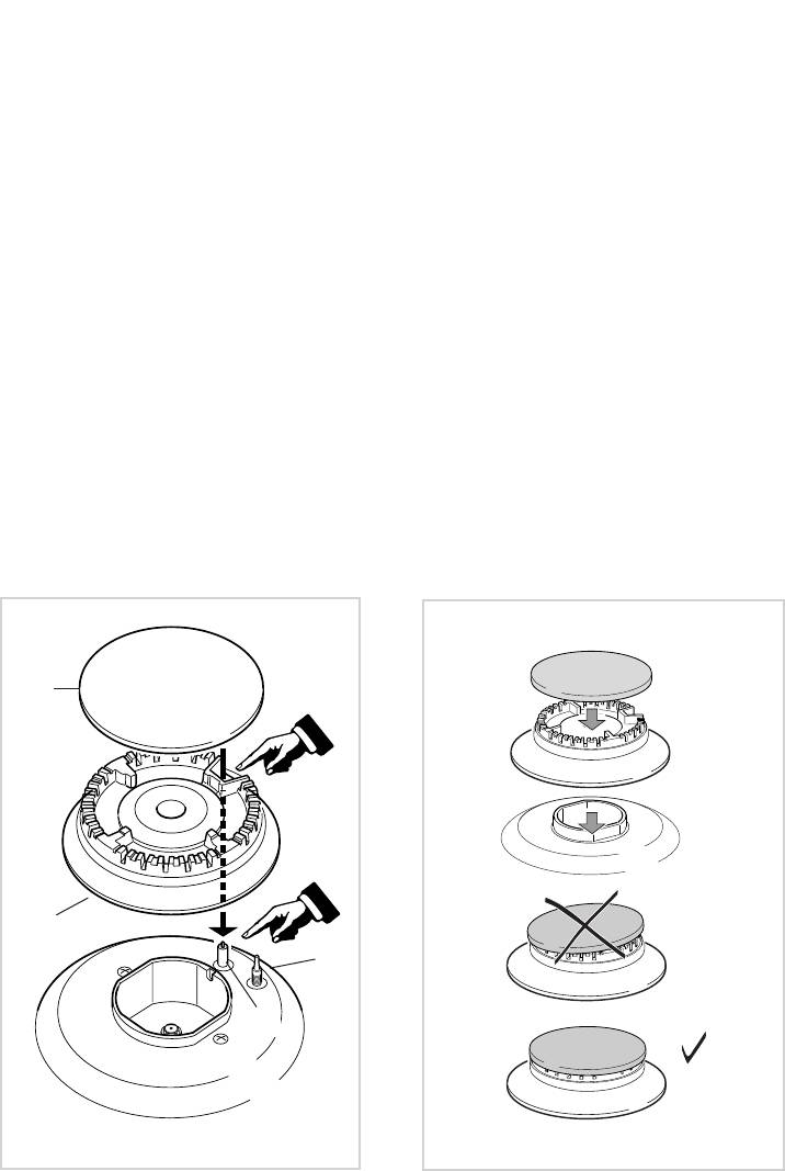
BURNERS
CORRECT REPLACEMENT OF
T
hey can be removed and washed with
THE BURNERS
soapy water only.
It is very important to check that the
They will remain always perfect if
burner flame distributor F and the cap C
cleaned with products used for silver-
has been correctly positioned (see fig.
ware.
6.2 - 6.3) - failure to do so can cause
After cleaning or wash, check that burn-
serious problems.
er-caps and burner-heads are dry before
placing them in the respective hous-
Check that the electrode “S” (fig. 6.2)
ings.
is always clean to ensure trouble-free
sparking.
It is very important to check that the
burner flame distributor and the cap has
Check that the probe “T” (fig. 6.2) next
been correctly positioned - failure to do
to each burner is always clean to ensure
so can cause serious problems.
correct operation of the safety valves.
Both the probe and ignition plug must be
Note: To avoid damage to the electric
very carefully cleaned.
ignition do not use it when the burn-
ers are not in place.
C
F
T
S
Fig. 6.2
Fig. 6.3
27
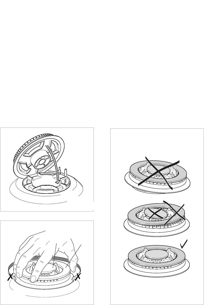
TRIPLE RING BURNER
(models with triple ring burner)
The triple ring burner must be correctly positioned (see fig. 6.4); the burner rib must be
enter in their logement as shown by the arrow.
Then position the cap A and the ring B (fig. 6.5 - 6.6).
The burner correctly positioned must not rotate (fig. 6.5).
Fig. 6.4
A
B
Fig. 6.5
Fig. 6.6
28
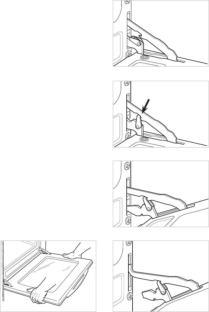
REMOVING THE OVEN DOOR
Fig. 6.7A
Type A
The oven door can easily be removed as
follows:
– Open the door to the full extent (fig.
6.7A).
– Attach the retaining rings to the hooks
on the left and right hinges (fig. 6.7B).
– Hold the door as shown in fig. 6.7.
Fig. 6.7B
– Gently close the door and withdraw
the lower hinge pins from their location
(fig. 6.7C).
– Withdraw the upper hinge pins from
their location (fig. 6.7D).
– Rest the door on a soft surface.
– To replace the door, repeat the above
steps in reverse order.
Fig. 6.7C
Fig. 6.7D
Fig. 6.7
29
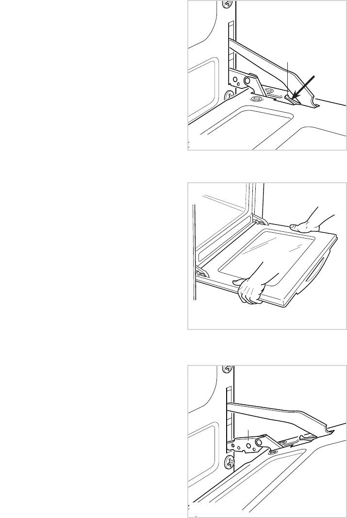
REMOVING THE OVEN DOOR
Type B
To facilitate oven cleaning, it is possible
to remove the door.
L
Please follow the instructions carefully:
– Open the door completely.
– Push down the lever “L” and, keeping it
in this position, slowly close the door in
order to block the hinge.
– Grip the door (as indicated in fig. 6.8)
and, while closing it, release the two
hinges as shown in fig. 6.10.
Рис. 6.8
DOOR ASSEMBLY
– Grip the door with your hands placed
near the hinges and raise the levers
“H” with your forefingers (fig. 6.10)
– Insert the hinges in their position until
levers “H” are hooked.
– Open the door completely to obtain the
release of levers “L”.
Рис. 6.9
H
Рис. 6.10
30
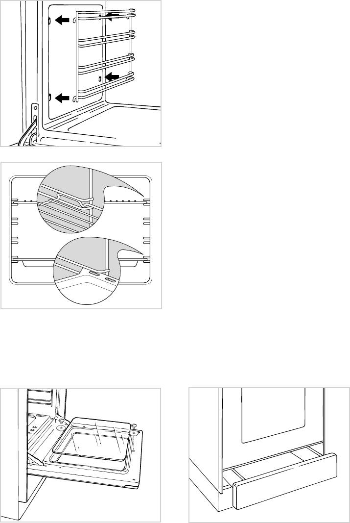
INSIDE OF OVEN
This must be cleaned every time it is
used.
Remove and refit the side runner frames
as described on the next chapter.
With the oven warm, wipe the inside walls
with a cloth soaked in very hot soapy
water or another suitable product.
Oven floor (models with gas oven only),
side runners frames, tray and rack can
be removed and washed in the sink.
Fig. 6.11
ASSEMBLY AND DISMANTLING
OF THE SIDE RUNNER
FRAMES
– Fit the side runner frames into the
holes on the side walls inside the
oven (Fig. 6.11).
– Slide the tray and rack into the run-
ners fig. 6.12. The shelf must be fitted
so that the safety catch, which stops
it sliding out, faces the inside of the
oven.
– To dismantle, operate in reverse order.
Fig. 6.12
OVEN DOOR
DRAWER
The internal glass of the oven door
The drawer (fig. 6.14) comes out like a
can be easily removed for cleaning by
normal drawer.
unscrewing the two lateral fixing screws
Do not store flammable material in
(Fig. 6.13).
the oven or in the drawer.
Fig. 6.13
Fig. 6.14

31
Advice
for
the installer
IMPORTANT
– Cooker installation must only be carried out by QUALIFIED TECHNICIANS and in
compliance with local safety standards. Failure to observe this rule will invalidate the
warranty.
The appliance must be installed in compliance with regulations in force in your country
and in observation of the manufacturer's instructions.
– Always unplug the appliance before carrying out any maintenance operations or repairs.
– The surfaces of adjacent furniture and walls must be capable of withstanding tempera-
tures in excess of 75˚C. If the cooker is installed adjacent to furniture which is higher
than the gas hob cooktop, a gap of at least 50 mm must be left between the side of the
cooker and the furniture.
– Some appliances are supplied with a protective film on steel and aluminium parts.
This film must be removed before using the cooker.
32
INSTALLATION
7
650 mm
450 mm
500 mm
50 mm min.
650 mm
450 mm
500 mm
50 mm min.
20 mm
20 mm
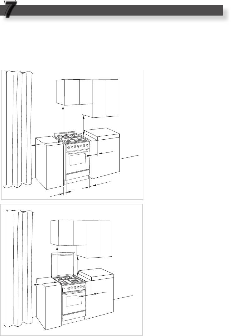
INSTALLING THE COOKERS
The installation conditions, concerning protection against overheating of the surfaces
adjacent to the cooker, must conform to figures 7.1a or 7.1b.
If the cooker is located on a pedestal it is necessary to provide safety measures to pre-
vent falling out.
The walls of the units
must be capable of resist-
ing temperatures of 75 °C
above room temperature.
■ Class 1
Gas connection made using
a rubber pipe which must
be visible and available for
inspection or using rigid or
flexible metal pipe.
Fig. 7.1a
■ Class 2
■ Subclass 1
Gas connecti o n m ad e
using a rigid or flexible
metal pipe.
Fig. 7.1b
33
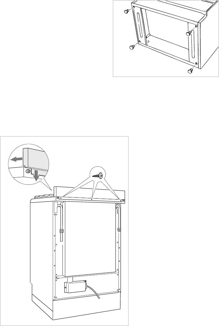
IMPORTANT
The cooker is equipped with 4 feet which
must be fitted to the base of the cooker:
Place the cooker on its back, as shown
in the figure 7.2, and fit the 4 feet.
Fig. 7.2
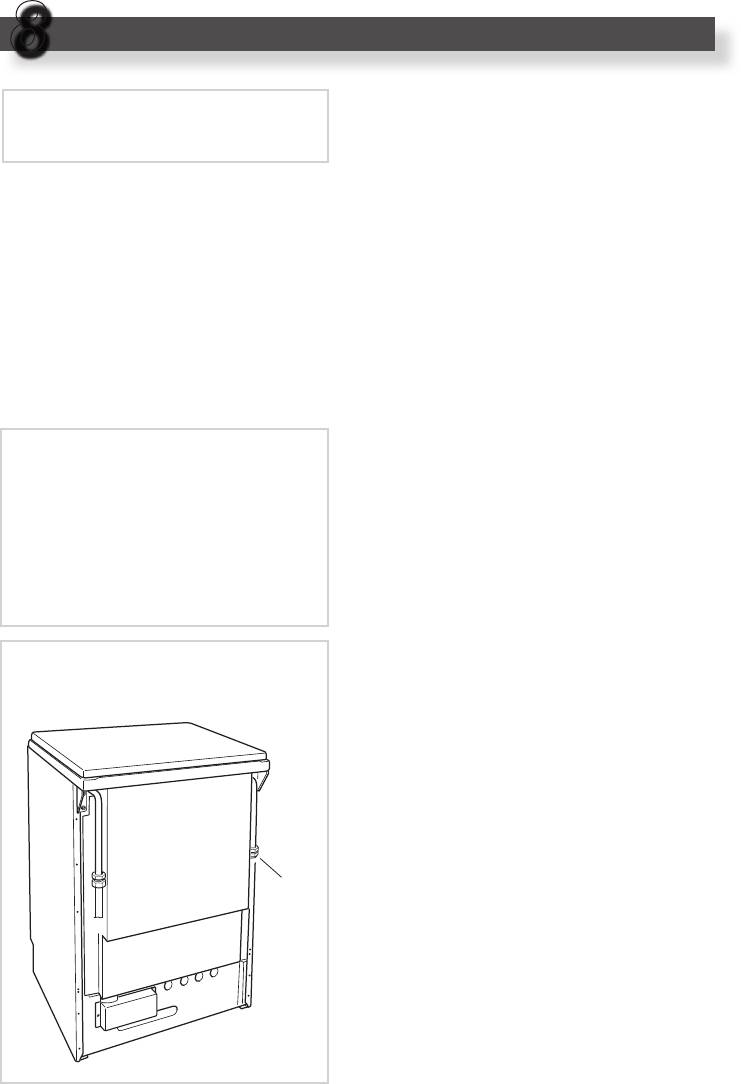
ASSEMBLING THE
BACKGUARD
(Model: PG.. 664 GGHI)
Assemble the backguard as
shown in figure 7.3 and fix it by
no.3 screws.
B
Fig. 7.3
34
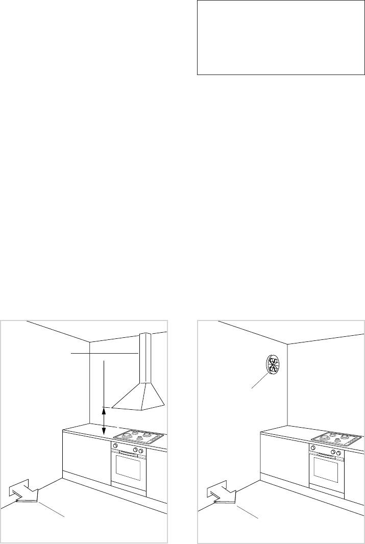
H min 650 mm
CHOOSING SUITABLE
This appliance is not connected to a
SURROUNDINGS
device to evacuate the combustion
In the room chosen to accommodate the
products. This must be installed and
gas appliance, there must be an ade-
connected in conformity with the
quate natural draft to allow combustion
installation rules in force. Pay special
of the gas.
care to room ventilation as well.
The natural draft must be produced
directly by one or more vents made in
DISCHARGING PRODUCTS OF
the external walls and providing a total
2
opening of at least 100 cm
.
COMBUSTION
The vents must be positioned close to
Extractor hoods connected directly to
the floor, preferably on the opposite side
the outside must be provided, to allow
to the combustion discharge outlet and
the products of combustion of the gas
must be designed in such a way that
appliance to be discharged (fig. 7.4).
they cannot be obstructed either from the
If this is not possible, an electric fan
inside or the outside.
may be used, attached to the external
When it is not possible to provide the
wall or the window; the fan should have
necessary vents, the draft may be sup-
a capacity to circulate air at an hourly
plied from an adjacent room, ventilated
rate of 3-5 times the total volume of the
in the required manner, provided it is not
kitchen (fig. 7.5).
a bedroom or an area at risk.
The fan can only be installed if the
In this event, the door of the kitchen must
room has suitable vents to allow air to
be opened to allow the draft to enter the
enter, as described under the heading
room.
“Choosing suitable surroundings”.
There must be a distance of at least 650
mm between the hob of the cooker and
any wall cupboard or extractor hood posi-
tioned immediately above (see fig. 7.4).
Extractor hood
for products of
combustion
Electric fan to
extract products
of combustion
Air vent
Air vent
Fig. 7.4
Fig. 7.5
35
GAS SECTION
8
GAS CONNECTION
The walls adjacent to the cooker
must be of material resistant to heat.
The connection must be executed by a
qualified technician according to the rel-
evant standard:
The appliance is predisposed and cali-
GAS TYPES
brated to operate with the gas indicated
The gases used for the operation of
on the specifications plate.
cooking appliances may be grouped by
their characteristics into two types:
Make sure that the room where the cook-
er will be installed has adequate ventila-
Cat: II 2H3+
tion, in conformity with the rules in force,
so that the appliance can work correctly;
then connect the cooker to the cylinder
– NATURAL GAS (G 20)
or gas pipe respecting the rules in force.
– L.P.G. (in cylinders) (G 30/G 31)
The connection must be executed to the
rear of appliance (left or right) (fig. 8.1);
the pipe do not cross the cooker.
The unused end inlet pipe of the cooker
Before installation, make sure that
(left or right) must be closed with the
the local distribution conditions
plug interposing the gasket.
(type of gas and its pressure) and
the adjustment of this appliance
are compatible. The appliance
adjustment conditions are given
If the appliance must be operated with a
on the plate or the label.
gas different than that indicated on the
plate, it is necessary to execute the fol-
lowing operations:
–
Gas connection.
– Replacement of the top injectors.
– Adjustment of the minimum of the top
burners.
For models with gas oven
:
– Substitution of the oven and grill injec-
tors
– Primary air of oven and grill burners
– Adjustment of the oven burner mini-
plug
mum
Fig. 8.1
36
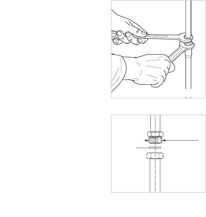
GAS CONNECTION WITH RIGID
METAL PIPE OR HOSE
The cooker must be connected to the
gas system using rigid metal pipes or
continuous wall stainless steel hoses
with threaded attachments, in conformity
with standard with maximum length of
2000 mm.
Be careful that metal hoses do not come
into contact with movable or crushed
parts.
The sealing gasket must conform to
standards.
The connection with rigid metal pipes
should not cause stresses to the gas
Fig. 8.2
inlet pipe.
IMPORTANT:
Always operate with 2 spanners (fig.
8.2).
½ G cylindrical
gas connection
After connecting to the mains, check
Gasket
that the couplings are correctly
sealed, using soapy solution, but
never a naked flame.
Fig. 8.3

37
IMPORTANT:
The gasket (fig. 8.3) is the element that
guarantees the seal in the gas con-
nection. It is recommended that it be
replaced whenever it shows even the
slightest deformation or imperfection.
In particular we recommend:
– That the connection with rigid metal
pipes should not cause stresses to the
gas inlet pipe.
– That the hose does not come into con-
tact with hot parts of the cooker at any
point.
– That the hose does not come into con-
tact with cutting or sharp edges.
– That the pipe should not be subject to
twisting and tensile stress and that it
should not have curves which are too
tight or be squashed.
– That the hose can be easily inspected
along its length to check its state of
wear.
– We advise replacing the hose at its
expiry date or on any sign of deterio-
ration.
– We advise replacing the gasket on the
slightest sign of deformation or imper-
fection.
– That the cylinder or piping tap is closed
immediately upstream of the appliance
whenever it is not being used.
38
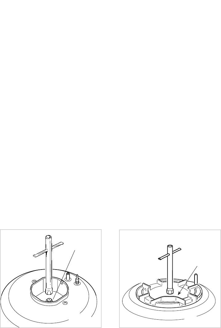
REPLACEMENT OF BURNER
The burners are conceived in such a
way so as not to require the regula-
INJECTORS
tion of the primary air.
If the injectors are not supplied they
can be obtained from the “Service
Centre”.
Select the injectors to be replaced
according to the “Table for the choice of
the injectors”.
The nozzle diameters, expressed in hun-
dredths of a millimetre, are marked on
the body of each injector.
To replace the injectors proceed as fol-
lows:
- Remove pan supports and burners
from the cooktop.
- Using a wrench, substitute the nozzle
injectors “J” (fig. 8.4, 8.5) with those
most suitable for the kind of gas for
which it is to be used.
J
J
Fig. 8.4
Fig. 8.5
39
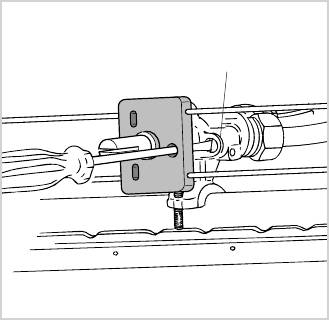
ADJUSTING OF THE MINIMUM
OF THE TOP BURNERS
The burners in the cooktop are fitted
with safety valves; the minimum flame
regulation screw is located on the out-
side of the gas tap (fig. 8.6).
In passing from one type of gas to anoth-
er, the gas flow must also be changed,
considering that in this position the flame
must have a length of about 4 mm and
must remain lit even with a brusque pas-
sage from the maximum position to that
of minimum.
The flame adjustment is done in the fol-
lowing way:
– Turn on the burner
– Turn the tap to the MINIMUM position
– Take off the knob
– With a thin screwdriver pass by the
hole of microswitch and turn the screw
F until adjustment is correct (fig. 8.6).
Normally for G 30/G 31, tighten up the
regulation screw.
F
Fig. 8.6
40
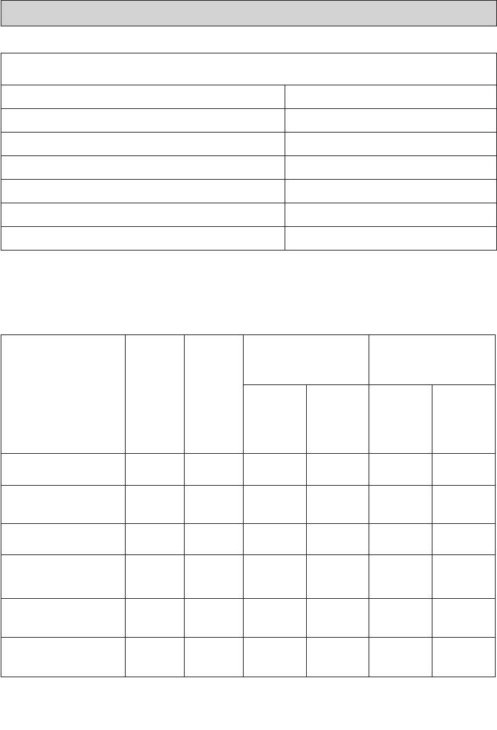
TABLE FOR THE CHOICE OF THE INJECTORS
3
Air vent necessary for gas combustion = (2 m
/h x kW)
BURNERS Air vent necessary [m3/h]
Auxiliary (A) 2
Semirapid (SR) 3,5
Rapid (R) 6,0
Triple ring (TR) 7,0
Oven 7,4
Grill 5,0
Cat: II 2H3+
G30/G31,
G30
28-30/37 mba
20 mba
NOMINAL
REDUCED
BURNERS
POWER
POWER
[kW]
[kW]
Ø injector
Tube ring
Ø injector
Tube ring
[1/100 mm]
opening [mm]
[1/100 mm]
opening [mm]
Auxiliary (A) 1,00 0,30 50 - 72 (X) -
Semirapid (SR) 1,75 0,45 65 - 97 (Z) -
Rapid (R) 3,00 0,75 85 - 115 (Y) -
Triple ring (TR) 3,50 1,50 95 - 135 (T) -
Fully open
Oven 3,70 1,00 92
140 5*
*
Fully open
Grill 2,50 80
120 4*
*
(
)
Reference value
*


