Delonghi PEMX 965 GHI – страница 2
Инструкция к Плите Delonghi PEMX 965 GHI
21
USE OF THE GRILL
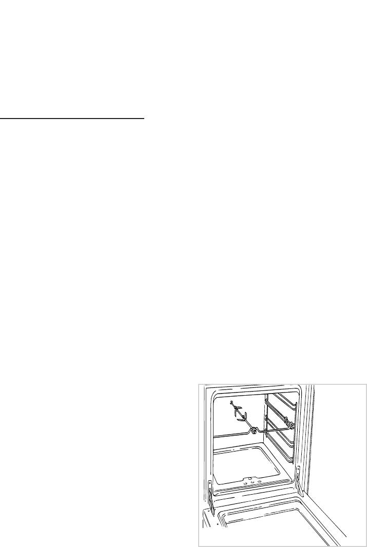
USE OF THE ROTISSERIE
Preheat the oven for about 5 min-
(fig. 4.3)
utes.
– Insert the dripping pan into the lowest
Introduce the food to be cooked,
rack holders of the oven and insert the
positioning the rack as close to the grill
rod support into the intermediate rack
as possible.
holders.
The drip tray should be placed under
– Put the meat to be cooked onto the
the rack to catch the cooking juices and
rod, being careful to secure it in the
fats.
center with the special forks.
Grill with the oven door closed.
– Insert the rod into the motor opening
and rest it onto the support of the spit
Do not grill for longer than 30 minutes
collar; then remove the grip by turning
at any one time.
it to the left.
Caution: the oven door becomes very
hot during operation. Keep children
well out of reach.
Fig. 4.3
22
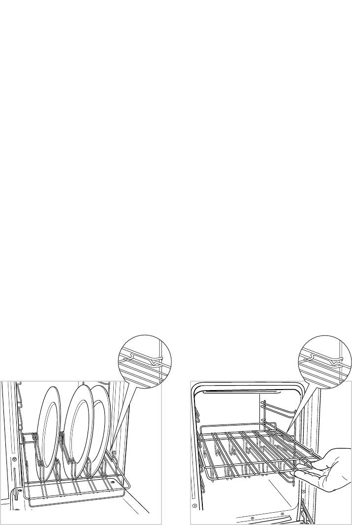
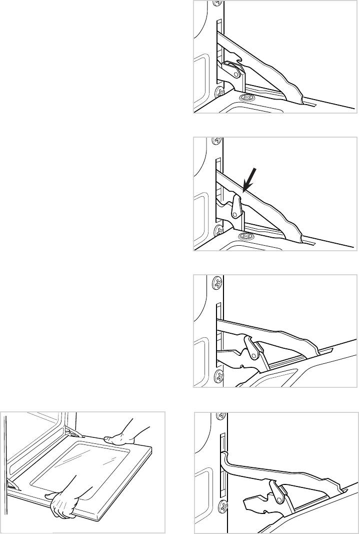
USE OF SPECIAL DISH RACK
USING THE SPECIAL RACK FOR
NORMAL COOKING
This special shelf can be used as a dish
rack or when turned over, as a normal
Slide in the shelf on the guides: the safe-
shelf for oven cooking.
ty catch must be turned toward the oven
It must be inserted between the guides of
base (see detail of figure 4.5).
The flat surface can be used to put cook-
the lateral racks.
ing pans or to put food directly on the
rack; in the second case the drip tray
should be placed under the rack to catch
the cooking juices and fats.
USING THE SPECIAL SHELF AS A
DISH RACK
Slide in the shelf on the guides, on the
lower level of the lateral racks.
The prongs where the plates are to be
inserted must be turned upwards.
The shelf must be fitted so that the safety
catch, which stops it sliding out, faces
the bottom of the oven (see detail of fig-
ure 4.4).
The plates must be positioned as indi-
cated in figure 4.4.
To facilitate this operation pull the special
rack up to the safety lock.
KEEP ATTENTION: Plates are hot after
warming. It is advisable to handle the
plates using oven gloves.
Fig. 4.4 Fig. 4.5
23
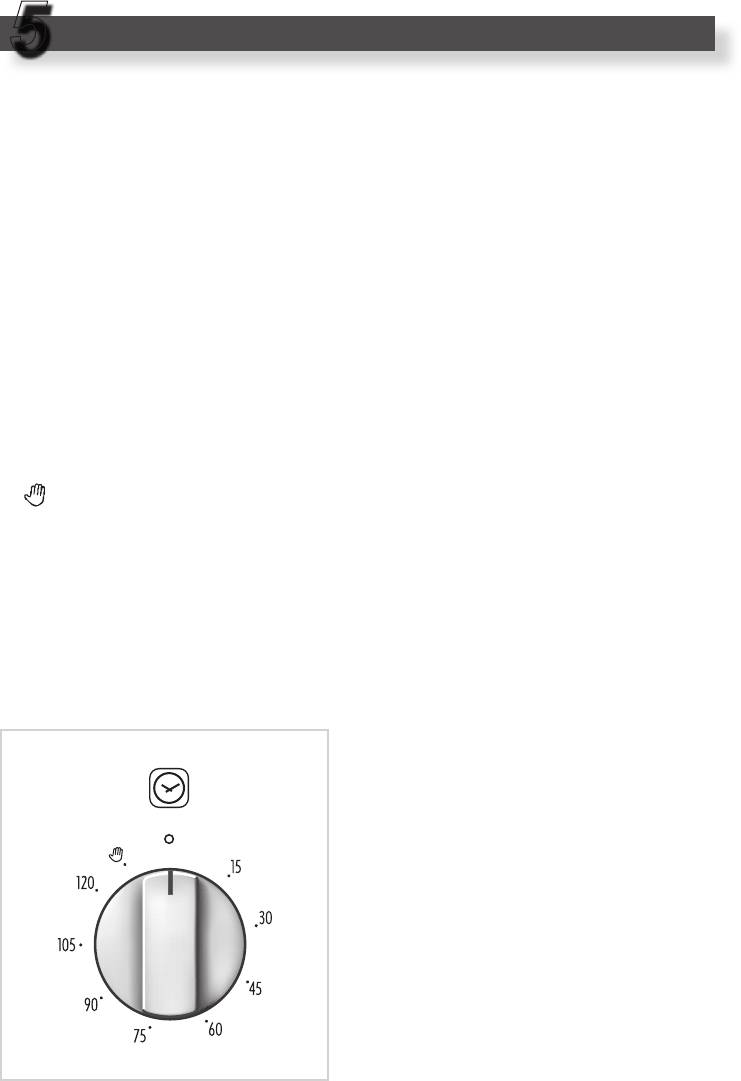
TIMER - 120’ Cut-off (Main oven only)
5
TIMER-120’ Cut-off
(Fig. 5.1)
The function of the timer runs the oven
for a preset time.
1) Starting up.
After setting the function selector and
thermostat to the required mode and
temperature, rotate the timer knob
clockwise until you reach the required
cooking time (max 120 minutes).
Once this time has elapsed, the timer
will return to the “0” position and the
oven will automatically switch off.
2) Manual position.
If the cooking time is longer than two
hours or if you wish to use the oven
manually, switching it off as required,
the knob must be turned to position
.
Fig. 5.1
24
CLEANING AND MAINTENANCE
6
GENERAL ADVICE
ENAMELLED PARTS
– Before any operation of cleaning
All the enamelled parts must be cleaned
and maintenance disconnect the
with a sponge and soapy water or other
appliance from the electrical net-
non-abrasive products.
work.
Dry preferably with a soft cloth.
– When the appliance is not being used,
Acidic substances like lemon juice,
it is advisable to keep the gas tap
tomato sauce, vinegar etc. can damage
closed.
the enamel if left too long.
– Every now and then check to make
sure that the flexible tube that con-
nects the gas line or the gas cylinder
to the appliance is in perfect condition
and eventually substitute it if it shows
signs of wearing or damage.
STAINLESS STEEL SURFACES
– Do not use cleaning products with a
chlorine or acidic base.
The stainless steel front panels on this
– If a tap becomes stiff, do not force;
cooker (facia, oven doors, drawer) are
contact your local Service Centre.
protected by a finger-print proof lacquer.
To avoid damaging this lacquer, do not
clean the stainless steel with abrasive
cleaners or abrasive cloths or scouring
pads.
ONLY SOAPY/WARM WATER MUST
BE USED TO CLEAN THE (COATED)
STAINLESS STEEL SURFACES.
GAS TAPS
In the event of operating faults in the gas
taps, call the Service Department.
REPLACING THE OVEN LIGHT
BULB
Switch the cooker off at the mains.
When the oven is cool, unscrew and
replace the bulb with another one
resistant to high temperatures (300 °C),
voltage 230 V (50 Hz), 15 W, E14.
Do not use a steam cleaner because
Note: Oven bulb replacement is not
the moisture can get into the appli-
covered by your guarantee.
ance thus make it unsafe.
25
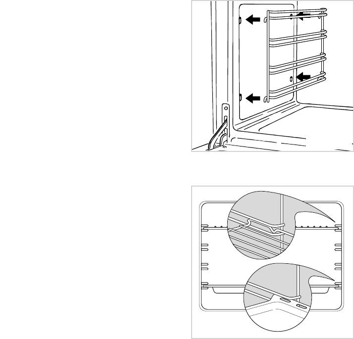
INSIDE OF OVEN
This must be cleaned after every use.
Remove and refit the side runner frames
as described on the next chapter.
With the oven warm, wipe the inside
walls with a cloth soaked in very hot
soapy water or another suitable product.
Side runner frames, tray and rack can
be removed and washed.
Fig. 6.1
ASSEMBLY AND DISMANTLING
OF THE SIDE RUNNER
FRAMES
– Fit the side runner frames into the
holes on the side walls inside the
oven (Fig. 6.1).
– Slide the tray and rack into the run-
ners fig. 6.2. The shelf must be fitted
so that the safety catch, which stops
it sliding out, faces the inside of the
oven.
– To dismantle, operate in reverse
order.
Fig. 6.2
26
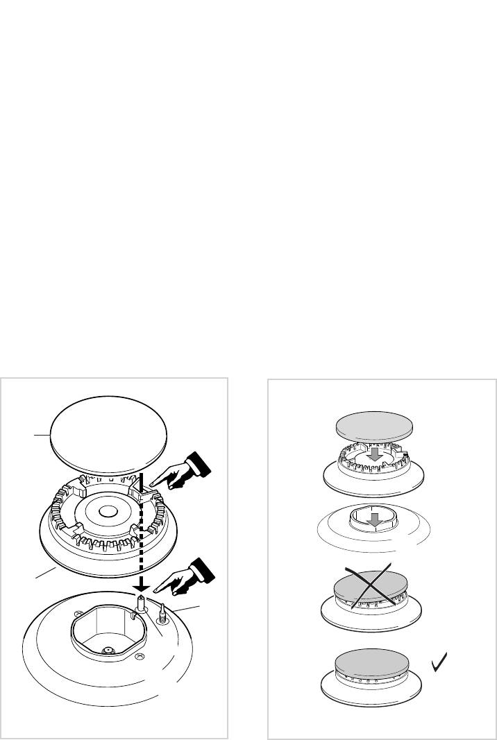
BURNERS
CORRECT REPLACEMENT OF
T
hey can be removed and washed with
THE BURNERS
soapy water only.
It is very important to check that the
They will remain always perfect if
burner flame distributor F and the cap C
cleaned with products used for silver-
has been correctly positioned (see fig.
ware.
6.3 - 6.4) - failure to do so can cause
After cleaning or wash, check that burn-
serious problems.
er-caps and burner-heads are dry before
placing them in the respective hous-
Check that the electrode “S” (fig. 6.3)
ings.
is always clean to ensure trouble-free
sparking.
It is very important to check that the
burner flame distributor and the cap has
Check that the probe “T” (fig. 6.3) next
been correctly positioned - failure to do
to each burner is always clean to ensure
so can cause serious problems.
correct operation of the safety valves.
Both the probe and ignition plug must be
Note: To avoid damage to the electric
very carefully cleaned.
ignition do not use it when the burn-
ers are not in place.
C
F
T
S
Fig. 6.3
Fig. 6.4
27
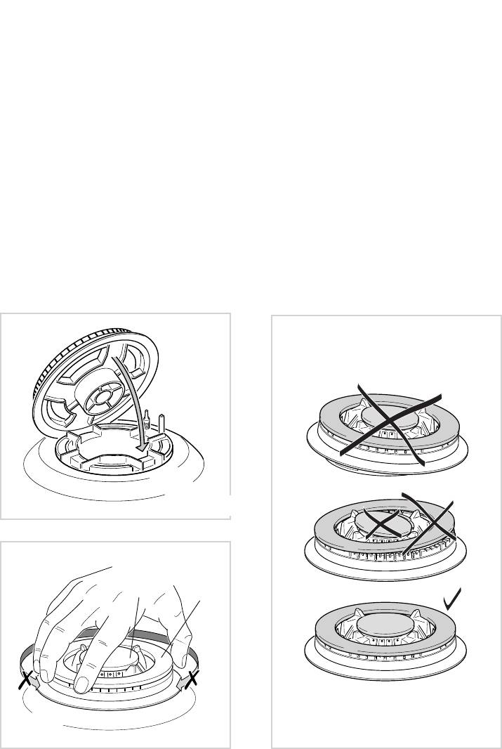
TRIPLE RING BURNER
The triple ring burner must be correctly positioned (see fig. 6.5); the burner rib must be
enter in their logement as shown by the arrow.
Then position the cap A and the ring B (fig. 6.6 - 6.7).
The burner correctly positioned must not rotate (fig. 6.6).
Fig. 6.5
A
B
Fig. 6.6
Fig. 6.7
28
Fig. 6.8
Fig. 6.9
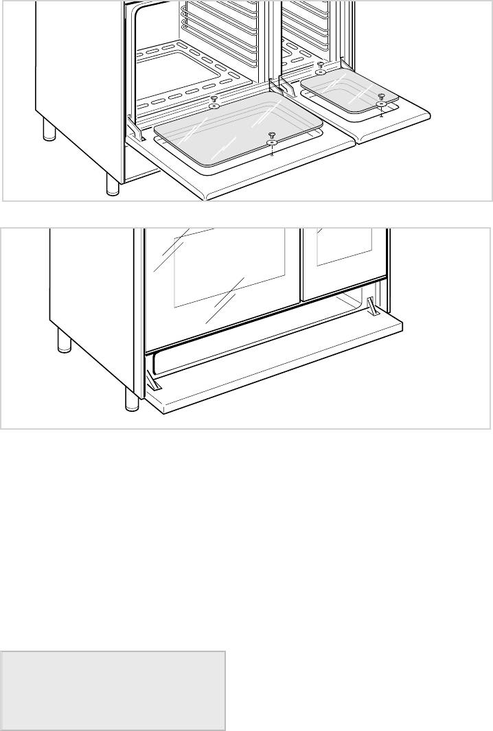
OVEN DOOR
STORAGE COMPARTMENT
The storage compartment is accessible
The internal glass panel can be easily
through the pivoting panel (fig. 6.9).
removed for cleaning by unscrewing the
2 retaining screws (Fig. 6.8)
Do not store flammable material in
the oven or in the storage compart-
ment.
29
REMOVING THE OVEN DOOR
Fig. 6.10a
The oven door can easily be removed
as follows:
– Open the door to the full extent (fig.
6.10a).
– Attach the retaining rings to the hooks
on the left and right hinges (fig. 6.10b).
– Hold the door as shown in fig. 6.10.
– Gently close the door and withdraw
Fig. 6.10b
the lower hinge pins from their loca-
tion (fig. 6.10c).
– Withdraw the upper hinge pins from
their location (fig. 6.10d).
– Rest the door on a soft surface.
– To replace the door, repeat the above
steps in reverse order.
Fig. 6.10c
Fig. 6.10d
Fig. 6.10

30
Advice
for
the installer
IMPORTANT
– Cooker installation must only be carried out by QUALIFIED TECHNICIANS and in
compliance with local safety standards. Failure to observe this rule will invalidate the
warranty.
The appliance must be installed in compliance with regulations in force in your country
and in observation of the manufacturer's instructions.
– Always unplug the appliance before carrying out any maintenance operations or repairs.
– The surfaces of adjacent furniture and walls must be capable of withstanding tempera-
tures in excess of 75˚C. If the cooker is installed adjacent to furniture which is higher
than the gas hob cooktop, a gap of at least 50 mm must be left between the side of the
cooker and the furniture.
– Some appliances are supplied with a protective film on steel and aluminium parts.
This film must be removed before using the cooker.
31
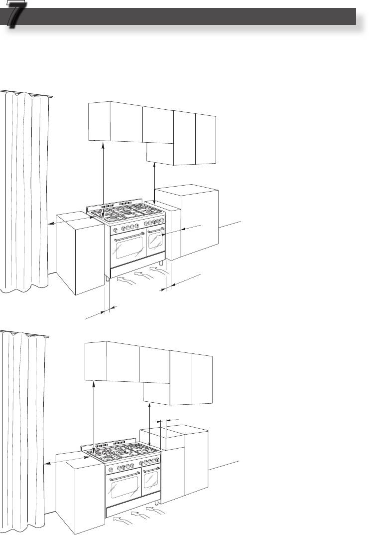
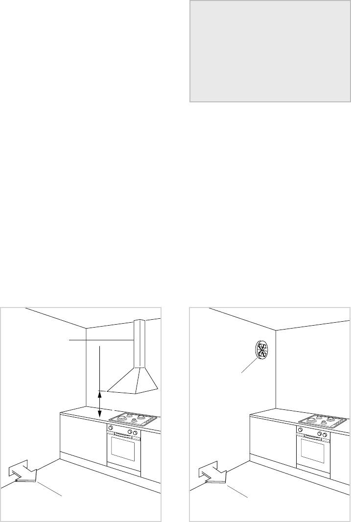
650 mm
50 mm
450 mm
500 mm
air vent
650 mm
450 mm
500 mm
50 mm
20 mm
air vent
20 mm
INSTALLATION
7
The installation conditions, concerning protection against overheating of the surfaces
adjacent to the cooker, must conform to figures 7.1a or 7.1b.
The walls of the units
must be capable of
resisting temperatures
of 75 °C above room
temperature.
■ Class 1
Gas connection made
using a rubber pipe
which must be visible
and available for inspec-
tion or using rigid or flex-
ible metal pipe.
Fig. 7.1a
■ Class 2
■ Subclass 1
Gas connection made
using a rigid or flexible
metal pipe.
Fig. 7.1b
32
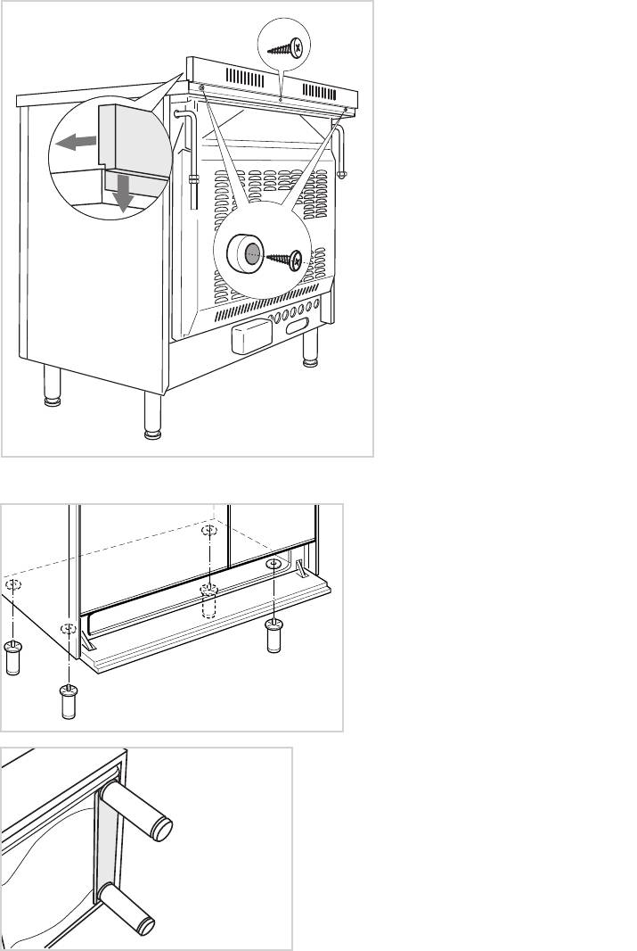
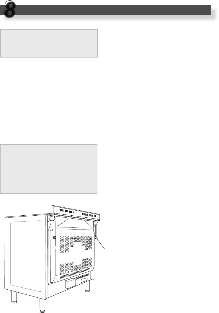
BACKGUARD
– Remove the two spacers “A” and
the screw “B” from the rear of the
cooker top.
– Assemble the backguard as
shown in figure 7.2 and fix it by
screwing the central screw “B”
and the spacers “A”.
FITTING THE ADJUSTABLE
FEET
The adjustable feet must be fitted to
the base of the cooker before use.
Rest the rear of the cooker on a
piece of the polystyrene packaging
exposing the base for the fitting of
the feet.
Fit the 4 legs by screwing them tight
Fig. 7.3
into the support base as shown in
figures 7.3 - 7.4.
Fig. 7.4
B
A
Fig. 7.2
33
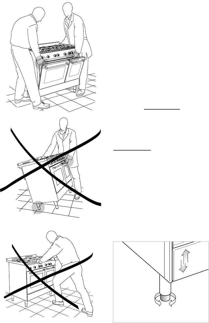
MOVING THE COOKER
WARNING
When raising cooker to upright posi-
tion always ensure two people carry
out this manoeuvre to prevent dam-
age to the adjustable feet and the
sides (fig. 7.5).
WARNING
Be carefull: DO NOT LIFT the cooker
Fig. 7.5
by the door handle when raising to the
upright position (fig. 7.6).
WARNING
When moving cooker to its final position
DO NOT DRAG (fig. 7.7).
Lift feet clear of floor (fig. 7.5).
LEVELLING THE COOKER
The cooker may be levelled by screw-
Fig. 7.6
ing the lower ends of the feet IN or OUT
(fig. 7.8).
Fig. 7.7
Fig. 7.8
34
H min 650 mm
CHOOSING SUITABLE
Installation technicians must com-
SURROUNDINGS
ply to current laws in force concern-
ing ventilation and the evacuation of
In the room chosen to accommodate the
exhaust gases.
gas appliance, there must be an ade-
Intensive and prolonged use may
quate natural draft to allow combustion
require extra ventilation, e.g. opening
of the gas.
a window, or more efficient ventilation
The natural draft must be produced
increasing the mechanical suction
directly by one or more vents made in
power if this is fitted.
the external walls and providing a total
2
opening of at least 100 cm
.
The vents must be positioned close to
the floor, preferably on the opposite side
DISCHARGING PRODUCTS OF
to the combustion discharge outlet and
COMBUSTION
must be designed in such a way that
they cannot be obstructed either from
Extractor hoods connected directly to
the inside or the outside.
the outside must be provided, to allow
When it is not possible to provide the
the products of combustion of the gas
necessary vents, the draft may be sup-
appliance to be discharged (fig. 7.9).
plied from an adjacent room, ventilated
If this is not possible, an electric fan
in the required manner, provided it is not
may be used, attached to the external
a bedroom or an area at risk.
wall or the window; the fan should have
In this event, the door of the kitchen
a capacity to circulate air at an hourly
must be opened to allow the draft to
rate of 3-5 times the total volume of the
enter the room.
kitchen (fig. 7.10).
There must be a distance of at least
The fan can only be installed if the
650 mm between the hob of the cook-
room has suitable vents to allow air to
er and any wall cupboard or extractor
enter, as described under the heading
hood positioned immediately above (see
“Choosing suitable surroundings”.
fig. 7.9).
Extractor hood
for products of
combustion
Electric fan to
extract products
of combustion
Air vent
Air vent
Fig. 7.9
Fig. 7.10
35
GAS SECTION
8
GAS CONNECTION
The walls adjacent to the cooker
The connection must be executed by a
must be of material resistant to
qualified technician according to the rel-
heat.
evant standard:
The appliance is predisposed and cali-
brated to operate with the gas indicated
GAS TYPES
on the specifications plate.
The gases used for the operation of
Make sure that the room where the cook-
cooking appliances may be grouped by
er will be installed has adequate ventila-
their characteristics into two types:
tion, in conformity with the rules in force,
so that the appliance can work correctly;
Cat: II 2H3+
then connect the cooker to the cylinder
or gas pipe respecting the rules in force.
The connection must be executed to the
– NATURAL GAS (G 20)
rear of appliance (left or right) (fig. 8.1);
– L.P.G. (in cylinders) (G 30/G 31)
the pipe do not cross the cooker.
The unused end inlet pipe of the cooker
(left or right) must be closed with the plug
interposing the gasket.
Before installation, make sure that
the local distribution conditions
(type of gas and its pressure) and
If the appliance must be operated with a
the adjustment of this appliance
gas different than that indicated on the
are compatible. The appliance
plate, it is necessary to execute the fol-
adjustment conditions are given on
lowing operations:
the plate or the label.
- Gas connection.
– Replacement of the top injectors.
– Adjustment of the minimum of the top
burners.
Plug
Fig. 8.1
36
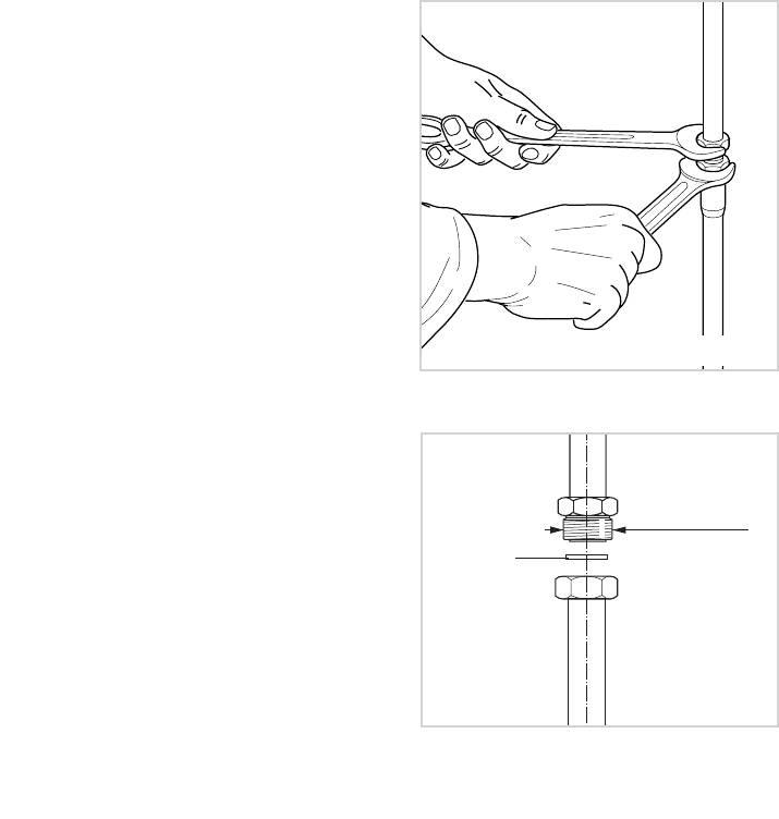
GAS CONNECTION WITH RIGID
METAL PIPE OR HOSE
The cooker must be connected to the
gas system using rigid metal pipes or
continuous wall stainless steel hoses
with threaded attachments, in conformity
with standard with maximum length of
2000 mm.
Be careful that metal hoses do not come
into contact with movable or crushed
parts.
The sealing gasket must conform to
standards.
The connection with rigid metal pipes
should not cause stresses to the gas
Fig. 8.2
inlet pipe.
IMPORTANT:
Always operate with 2 spanners (fig.
8.2).
½ G cylindrical
gas connection
After connecting to the mains, check
Gasket
that the couplings are correctly
sealed, using soapy solution, but
never a naked flame.
Fig. 8.3

37
IMPORTANT:
The gasket “D” (fig. 8.3) is the element
that guarantees the seal in the gas con-
nection. It is recommended that it be
replaced whenever it shows even the
slightest deformation or imperfection.
In particular we recommend:
– That the connection with rigid metal
pipes should not cause stresses to the
gas inlet pipe.
– That the hose does not come into con-
tact with hot parts of the cooker at any
point.
– That the hose does not come into con-
tact with cutting or sharp edges.
– That the pipe should not be subject to
twisting and tensile stress and that it
should not have curves which are too
tight or be squashed.
– That the hose can be easily inspected
along its length to check its state of
wear.
– We advise replacing the hose at its
expiry date or on any sign of deterio-
ration.
– We advise replacing the gasket on the
slightest sign of deformation or imper-
fection.
– That the cylinder or piping tap is closed
immediately upstream of the appliance
whenever it is not being used.
38
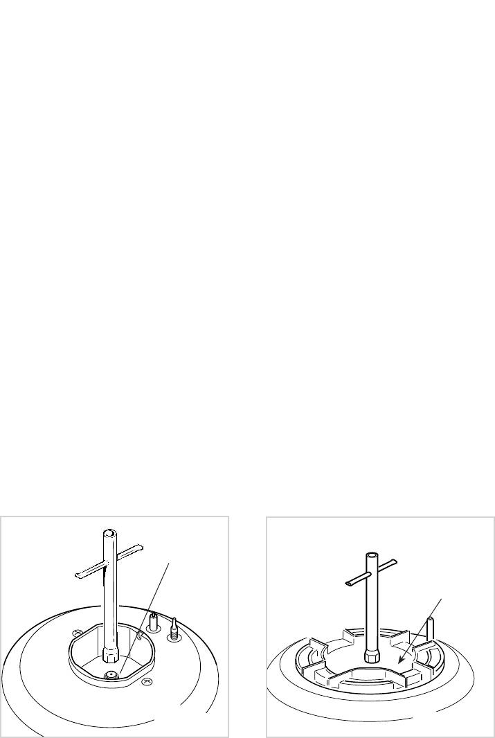
REPLACEMENT OF BURNER
The burners are conceived in such a
way so as not to require the regula-
INJECTORS
tion of the primary air.
If the injectors are not supplied they
can be obtained from the “Service
Centre”.
Select the injectors to be replaced
according to the “Table for the choice of
the injectors”.
The nozzle diameters, expressed in hun-
dredths of a millimetre, are marked on
the body of each injector.
To replace the injectors proceed as fol-
lows:
- Remove pan supports and burners
from the cooktop.
- Using a wrench, substitute the nozzle
injectors “J” (figs. 8.4, 8.5) with those
most suitable for the kind of gas for
which it is to be used.
J
J
Fig. 8.4
Fig. 8.5
39
TABLE FOR THE CHOICE OF THE INJECTORS
3
Air vent necessary for gas combustion = (2 m
/h x kW)
BURNERS Air vent necessary [m3/h]
Auxiliary (A) 2
Semirapid (SR) 3,5
Rapid (R) 6,0
Triple ring (TR) 7,0
Cat: II 2H3+
G30/G31,
G20
28-30/37 mbar
20 mbar
NOMINAL
REDUCED
BURNERS
POWER
POWER
[kW]
[kW]
Ø injector
Ø injector
[1/100 mm]
[1/100 mm]
Auxiliary (A) 1,00 0,30 50 72 (X)
Semirapid (SR) 1,75 0,45 65 97 (Z)
Rapid (R) 3,00 0,75 85 115 (Y)
Triple ring (TR) 3,50 1,50 95 135 (T)
IMPORTANT
All intervention regarding installation maintenance of the appliance must be
fulfilled with original factory parts.
The manufacturer declines any liability resulting from the non-compliance of this
obligation.
40
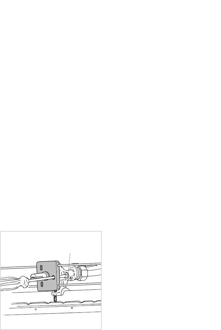
ADJUSTING OF THE MINIMUM
LUBRICATION OF THE GAS
OF THE TOP BURNERS
TAPS
In passing from one type of gas to anoth-
– In case of difficulty in the gas
er, the gas flow must also be changed,
taps operation, call the After Sales
considering that in this position the flame
Service.
must have a length of about 4 mm and
must remain lit even with a brusque pas-
sage from the maximum position to that
of minimum.
The flame adjustment is done in the fol-
lowing way:
– Turn on the burner
– Turn the tap to the MINIMUM position
– Take off the knob
– With a thin screwdriver pass by the
hole of microswitch and turn the screw
F until adjustment is correct (fig. 8.6).
Normally for G 30/G 31, tighten up the
regulation screw.
F
Fig. 8.6


