Stiebel Eltron HDB-E Si 01.11.2012 - 31.01.2013: INSTALLATION
INSTALLATION: Stiebel Eltron HDB-E Si 01.11.2012 - 31.01.2013
EN
GL
ISH
www.stiebel-eltron.com
HDB-E Si |
19
INSTALLATION Safety
INSTALLATION
7. Safety
Only a qualified contractor should carry out installation, commis-
sioning, maintenance and repair of the appliance.
7.1
General safety instructions
We guarantee trouble-free operation and operational reliability
only if the original accessories and spare parts intended for the
appliance are used.
!
Material damage
Observe the maximum inlet temperature. The appliance
can be damaged by higher temperatures.
7.2
Regulations, standards and instructions
Note
Observe all applicable national and local instructions and
regulations, e.g. DIN 1988 / DIN EN 806 in Germany.
- The protection rating IP 25 (hoseproof) can only be ensured
with a correctly fitted cable grommet.
- The specific electrical resistance of the water must not fall
below that stated on the type plate. In a linked water net-
work, observe the lowest electrical water resistance (see
chapter “Specification / Application areas”). Your water
supply utility will advise you of the specific electrical water
resistance or conductivity.
8. Appliance description
8.1 Standard
delivery
- Mounting bracket
- Twin nipple
- Flat gaskets
- Strainer
- Flow limiter
- Plastic profile washer
8.2 Accessories
Universal mounting frame
Mounting frame with electrical connections.
Pipe assembly DHB water plug-in couplings
2 water plug-in couplings allow the appliance to be connected to
the available water plug-in connections of a DHB.
Load shedding relay (LR 1-A)
The load shedding relay which needs to be installed in the dis-
tribution board provides priority control for the instantaneous
water heater when operating, for example, electric storage heat-
ers simultaneously.
9. Preparations
f
Flush the water line thoroughly.
Taps/valves
f
Use appropriate pressure-tested taps. Open taps are not
permitted.
A safety valve is not required.
Permissible water pipe materials
- Cold water inlet pipe:
Galvanised steel pipe, stainless steel pipe, copper pipe or
plastic pipe
- DHW outlet pipe:
Stainless steel pipe, copper pipe or plastic pipe
!
Material damage
If plastic pipework systems are used, take into account
the maximum inlet temperature and the maximum pres-
sure (see chapter “Specification / Data table”).
Flow rate
f
Ensure that the flow rate (see chapter “Specification / Data
table”, On) for switching on the appliance is achieved.
f
Increase the mains water pressure if the required flow rate is
not achieved with the draw-off valve fully opened.
Flow pressure
If the minimum flow rate required for the appliance to switch on is
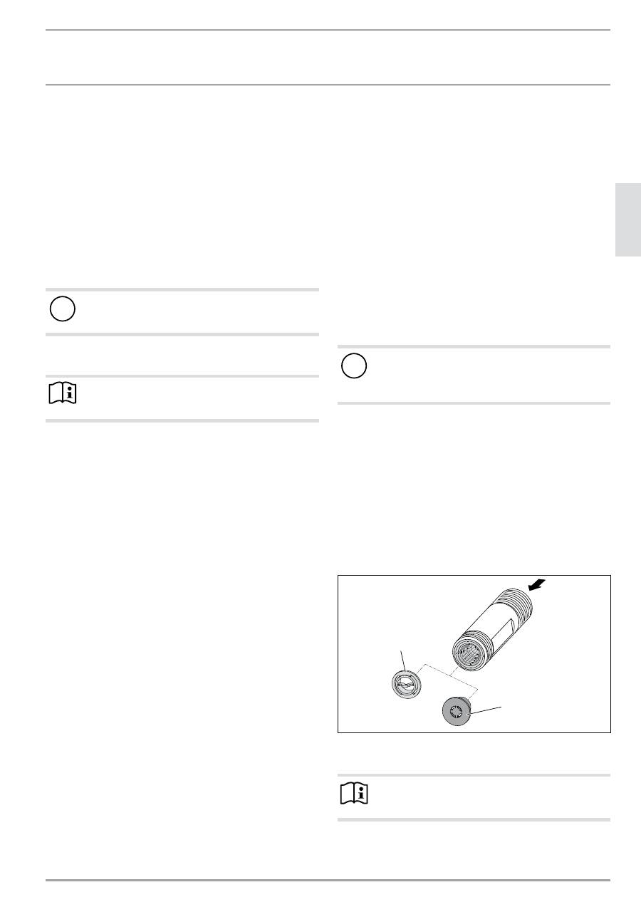
not achieved even with the tap fully open, remove the flow limiter.
Replace it with the plastic profile washer supplied. If required the
pressure in the water installation can also be raised.
2
6
_0
2_0
2_
1
3
6
3
2
1
1 Flow limiter
2 Plastic profile washer
Note
Always use a flow limiter when operating the appliance
with a thermostatic valve.
20
| HDB-E Si
www.stiebel-eltron.com
INSTALLATION Installation
Flexible water connection lines
f
If the appliance is installed with flexible water connection
lines, ensure that the pipe bends do not become twisted.
Pipe bends have a bayonet fitting and are installed inside the
appliance.
f
Secure the back panel at the bottom with an additional
screw.
9.1 Installation
site
!
Material damage
Install the appliance in a room free from the risk of frost.
f
Always install the appliance vertically near the draw-off
point.
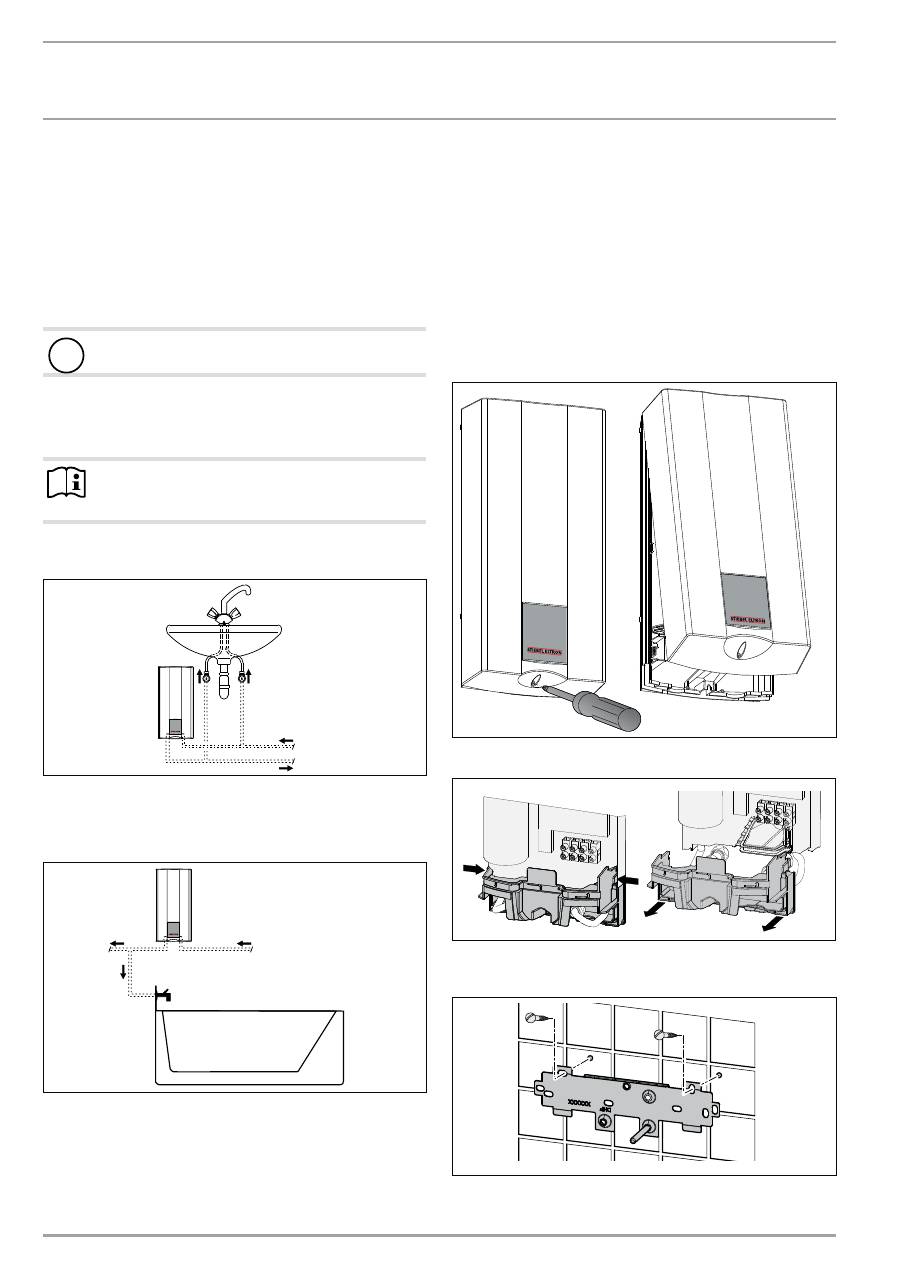
The appliance is suitable for undersink and oversink installations.
Note
The appliance must be fitted to a wall with sufficient
load-bearing capacity.
Undersink installation
26
_0
2
_02
_1
37
3
1
2
1 Cold water inlet
2 DHW outlet
Oversink installation
2
6
_0
2_0
2_
1
3
7
4
1
2
1 Cold water inlet
2 DHW outlet
9.2 Factory
settings
The appliances are prepared in the delivered condition:
- Power supply from “below”, installation on unfinished walls
- Water connection, installation on unfinished walls
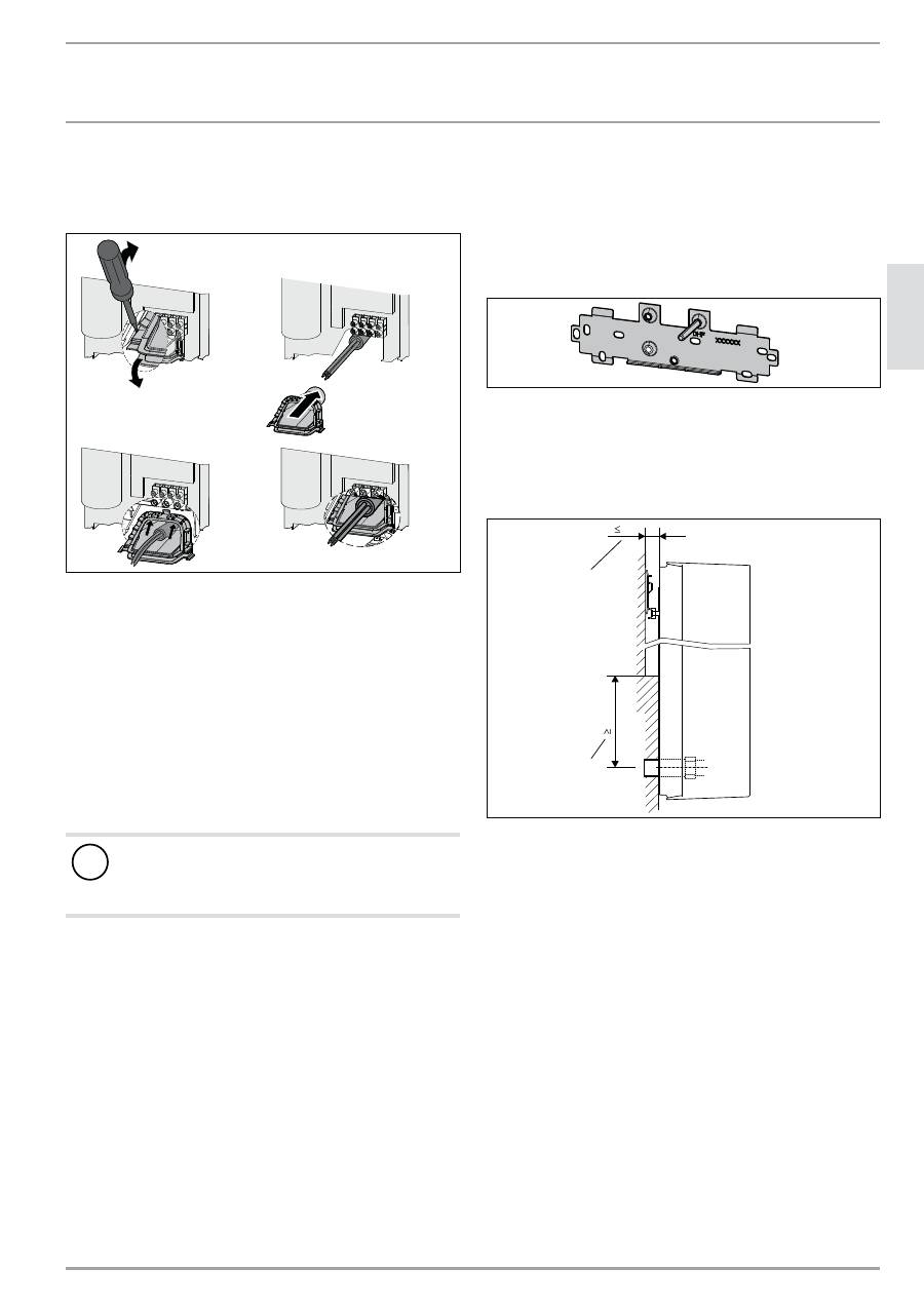
10. Installation
This chapter describes installation in accordance with the factory
settings.
For further installation options, see chapter “Installation alterna-
tives”.
26
_0
2
_02
_1
3
6
7
f
Open the appliance.
2
6
_0
2_0
2_
1
1
0
1
f
Press the two locking hooks and remove the lower part of
the back panel towards the front.
2
6
_0
2_0
2
_0
8
1
0_
f
Mark out the holes to be drilled; see chapter “Specification /
Dimensions and connections”.
EN
GL
ISH
www.stiebel-eltron.com
HDB-E Si |
21
INSTALLATION Installation
f
Drill the holes and secure the mounting bracket with
2 screws and 2 rawl plugs (screws and rawl plugs are not
part of the standard delivery).
Note
If you are installing the appliance with flexible water con-
nections, secure the back panel with a screw.
f
Fit the mounting bracket.
160
30
26
_0
2
_02
_0
8
8
7
f
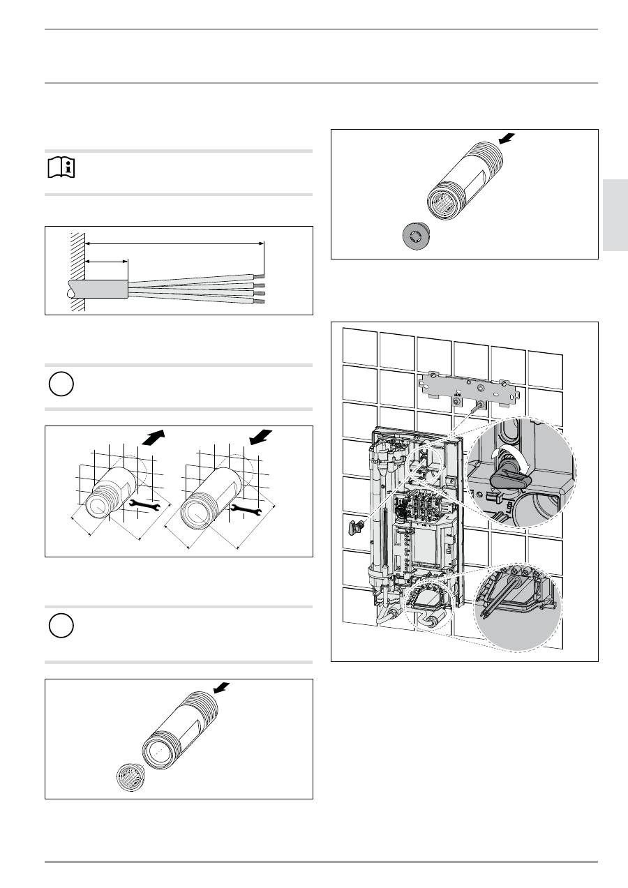
Prepare the power cable.
Making the water connection
!
Material damage
Carry out all water connection and installation work in
accordance with regulations.
68 ±2
53 ±2
19
G 3/8
A
19
G 1/2
A
26
_0
2
_02
_1
3
6
8
f
Seal and insert the twin nipples.
Fitting the strainer
!
Material damage
The strainer must be fitted for the appliance to function.
f
When replacing the appliance, check that the strain-
er is present.
2
6
_0
2_0
2_
1
3
6
4
f
Fit the strainer provided in the cold water inlet of the
appliance.
Installing the DMB flow limiter
26
_0
2
_02
_1
3
6
5
f
Install the flow limiter provided in the cold water inlet of the
appliance.
Installing the appliance
2
6
_0
2_0
2_
1
3
7
2
f
For easy installation, push the cable grommet of the upper
electrical connection into the back panel from behind.
f
Remove the transport plugs from the water connections.
f
Remove the fixing toggle from the upper part of the back
panel.
f
Route the power cable from behind through the cable grom-
met until it rests against the cable sheath. Align the power
cable.
In the case of a cross-section > 6 mm², enlarge the hole in
the cable grommet.
f
Push the appliance over the threaded stud of the mounting
bracket, so that it breaks through the soft seal. If necessary,
use a screwdriver.
22
| HDB-E Si
www.stiebel-eltron.com
INSTALLATION Installation
f
Push the fixing toggle onto the threaded stud of the mount-
ing bracket.
f
Press the back panel firmly into place and lock the fixing tog-
gle by turning it through 90°.
19
24
26
_0
2
_02
_1
3
6
9
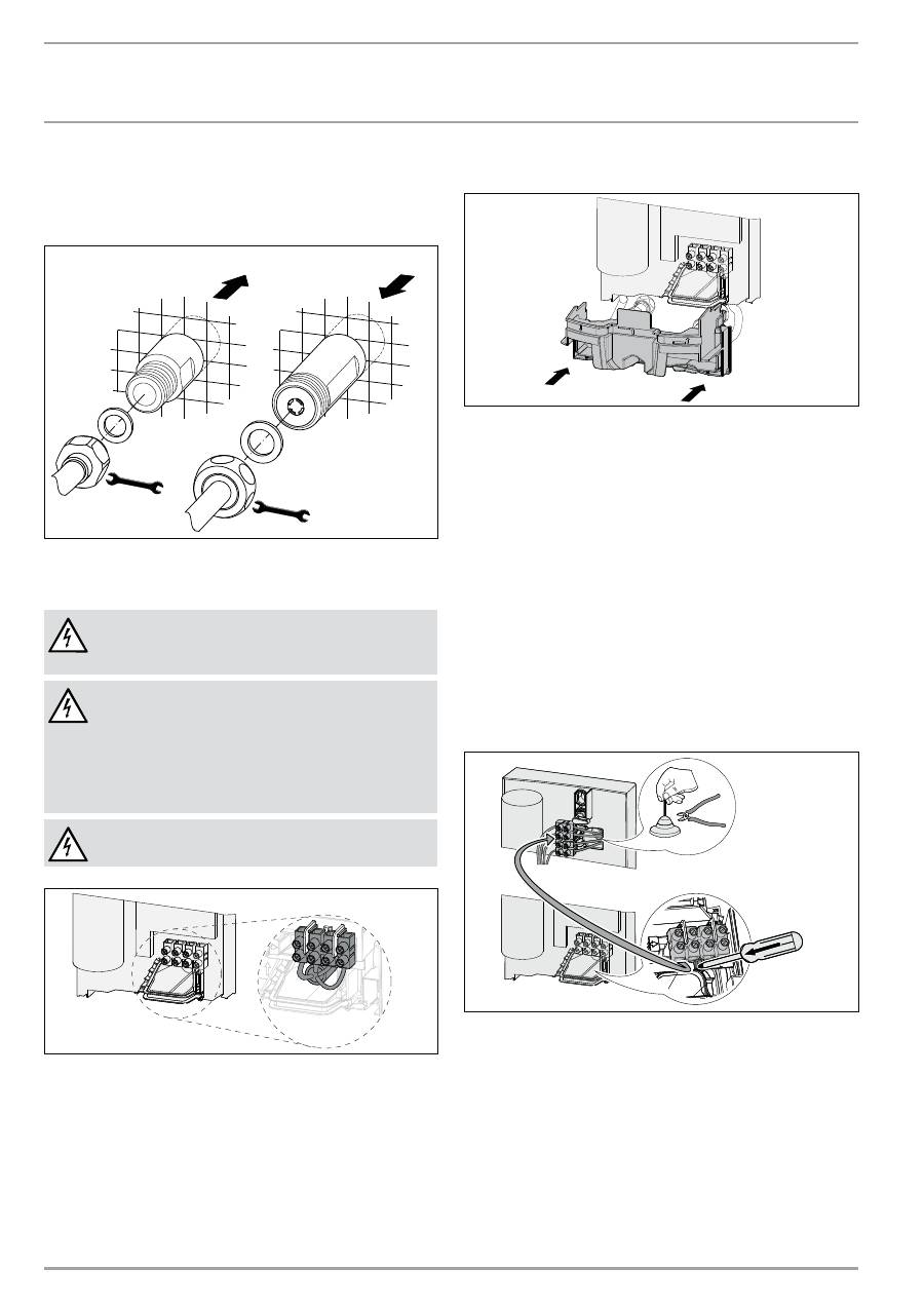
f
Fit the pipes with flat gaskets onto the twin nipples.
Connecting the power supply
WARNING Electrocution
Carry out all electrical connection and installation work
in accordance with relevant regulations.
WARNING Electrocution
Connection to the power supply is only permissible in the
form of a permanent connection in conjunction with the
removable cable grommet. The appliance must be able
to be separated from the power supply by an isolator
that disconnects all poles with at least 3 mm contact
separation.
WARNING Electrocution
Ensure that the appliance is earthed.
2
6
_0
2_0
2
_1
1
2
2_
f
Connect the power cable to the mains terminal (see chapter
“Specification / Wiring diagram”). The specified voltage must
match the mains voltage.
10.1 Completing the installation
26
_0
2
_02
_1
1
0
2
_
f
Fit the lower part of the back panel. Ensure that it clicks into
place.
f
Align the appliance by carrying out the following: Loosen
the fixing toggle and align the power supply and back panel.
Retighten the fixing toggle. If the back panel of the appliance
is not flush, the appliance can be secured at the bottom with
an additional screw.
10.2 Alternative installation methods
- Power supply from above for unfinished walls
- large cross-section for power supply from below
- Connecting a load shedding relay
- Use of existing mounting bracket when replacing an
appliance
- Installation for offset tiles
Power supply from above for unfinished walls
2
6
_0
2_0
2_
1
1
2
3
_
f
Cut off the cable grommet for the power cable.
f
Push down and remove the locking hook that secures the
mains terminal, then remove the mains terminal.
f
Reposition the mains terminal from the bottom to the top.
Secure the mains terminal by pushing it under the locking
hook.
EN
GL
ISH
www.stiebel-eltron.com
HDB-E Si |
23
INSTALLATION Installation
Conductor cross-sections for power supply from below
If cables with a large cross-section are used, the cable grommet
can be fitted after the appliance has been installed.
1.
3.
4.
2.
26
_0
2
_02
_1
370
f
Before installing the appliance, use a screwdriver to push the
cable grommet out.
f
Push the cable grommet over the power cable. In the case
of a cross-section > 6 mm², enlarge the hole in the cable
grommet.
f
Push the cable grommet into the back panel and click grom-
met into place.
Connecting a load shedding relay
Install the load shedding relay in the distribution board in conjunc-
tion with other electric appliances, e.g. electric storage heaters.
The relay responds when the instantaneous water heater starts.
The load shedding relay is available as an accessory.
!
Material damage
Connect the phase that switches the load shedding relay
to the indicated terminal of the mains terminal in the
appliance (see chapter “Specification / Wiring diagram”).
Mounting bracket for appliance replacement
Am existing Stiebel Eltron mounting bracket may be used when
replacing appliances (except instantaneous water heater DHF).
f
Break through the back panel of the appliance for the thread-
ed stud on the pre-installed mounting bracket.
DHF replacement
26
_0
2
_02
_0
8
1
5
_
f
Reposition the threaded stud on the mounting bracket (the
stud has a self-tapping thread).
f
Rotate the mounting bracket through 180° and mount it on
the wall (the DHF logo is then turned towards the reader).
Installation for offset tiles
110
20
26
_0
2
_02
_1
37
1
2
1
1 Minimum contact area of the appliance
2 Maximum tile offset
f
Adjust the wall clearance and lock the back panel with the
fixing toggle by turning it clockwise through 90°.
24
| HDB-E Si
www.stiebel-eltron.com
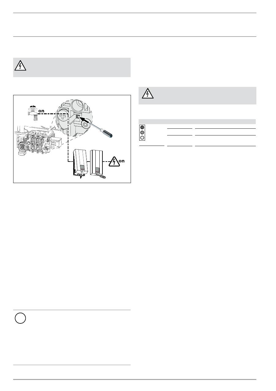
INSTALLATION Commissioning 11. Commissioning
WARNING Electrocution
Commissioning may only be carried out by an authorised
contractor in accordance with safety regulations.
11.1 Commissioning
26
_0
2
_02
_1
375
f
Open and close all connected draw-off valves several times,
until all air has been vented from the pipework and the
appliance.
f
Carry out a tightness check.
f
Activate the safety pressure limiter. The instantaneous water
heater is supplied with the safety pressure limiter in the trig-
gered state. Activate the safety pressure limiter at flow pres-
sure by pressing the reset button with a screwdriver.
f
Fit the appliance cap and secure it with a screw.
f
Switch the mains power ON.
f
Check the function of the appliance.
f
Remove the protective foil from the user interface.
Appliance handover
f
Explain the appliance function to users and familiarise them
with its operation.
f
Make users aware of potential dangers, especially the risk of
scalding.
f
Hand over these instructions.
11.2 Recommissioning
!
Material damage
Following an interruption of the water supply, recommis-
sion the appliance by carrying out the following steps, in
order to prevent the destruction of the bare wire heating
system.
f
Disconnect the appliance from the power supply by
removing the fuses/tripping the MCBs.
f
Open the tap until the appliance and its upstream
cold water inlet line are free of air.
f
Switch the mains power back ON again.
12. Shutting down
f
Isolate all poles of the appliance from the power supply.
f
Drain the appliance (see chapter “Maintenance”).
13. Troubleshooting
WARNING Electrocution
In order to check the appliance, it must be supplied
with power.
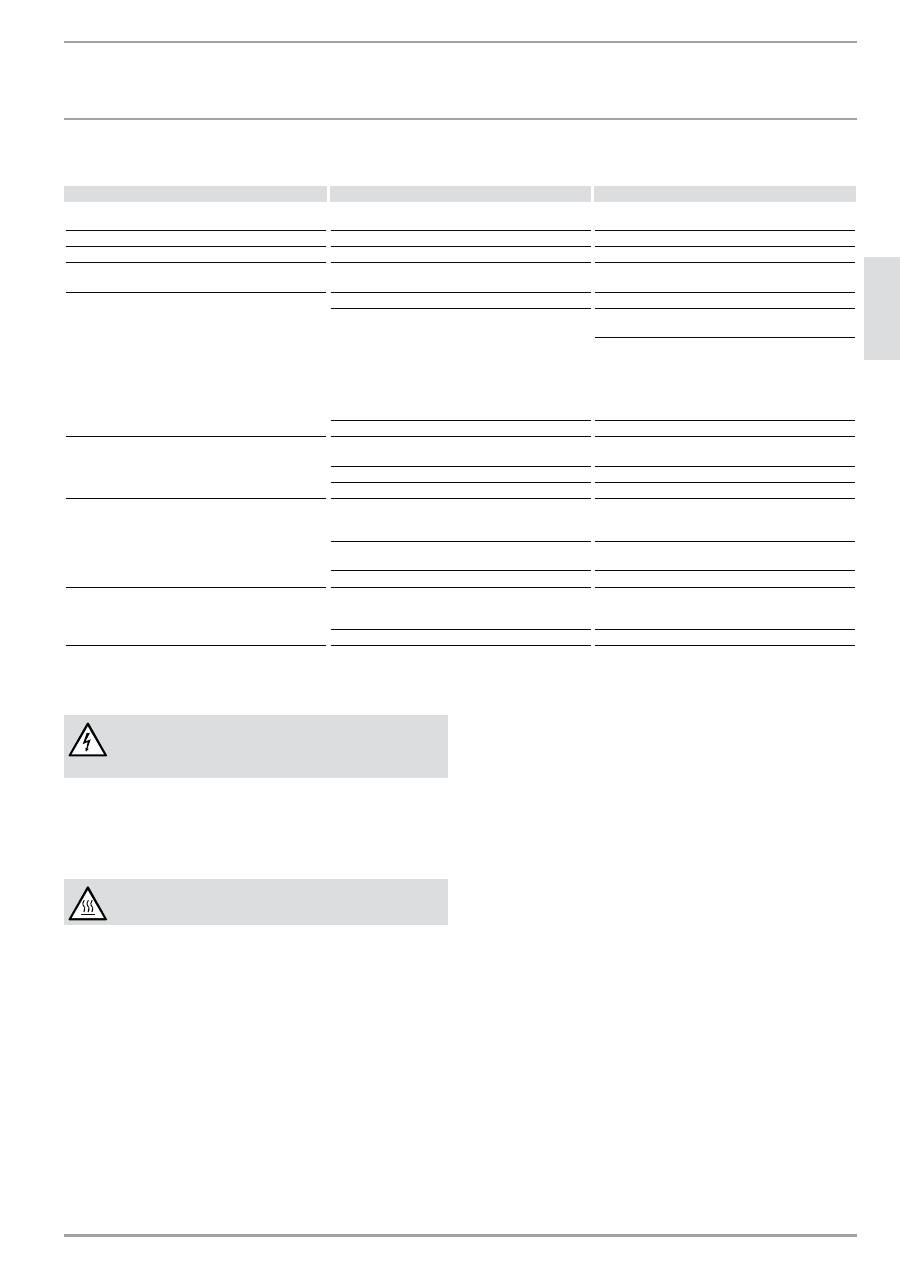
13.1 Display options for LED diagnostic traffic light
Possible indications
Red
Illuminates in case of faults
Yellow
Illuminates in heating mode
Green
Flashing: appliance is supplied with
mains power
EN
GL
ISH
www.stiebel-eltron.com
HDB-E Si |
25
INSTALLATION Maintenance
13.2 Fault
table
Fault / diagnostic traffic light LED display Cause
f
Remedy
The appliance does not start.
The shower head / aerators are scaled up.
Descale or if necessary replace the shower head /
aerators.
Inadequate flow rate.
The sieve in the appliance is dirty.
Clean the strainer.
The temperature is not achieved.
One phase down.
Check the MCB/fuse in your fuse box.
The heater does not switch on.
The air sensor detects the presence of air in the
water and briefly switches the heater off.
The appliance restarts after one minute.
No hot water and no traffic light display.
The MCB/fuse has responded/blown.
Check the MCB/fuse in your fuse box.
The safety pressure limiter (see chapter “Specifica-
tion / Wiring diagram” has switched off.
Remove the cause of the fault (e.g. faulty pressure
washer).
Protect the heating system against overheating by
opening a draw-off valve downstream from the ap-
pliance for one minute. This depressurises and cools
down the heater. Activate the safety pressure limiter
at flow pressure by pressing the reset button; see
also chapter “Commissioning”.
The PCB is faulty.
Check the PCB and replace if necessary.
No hot water at flow rate of > 23 l/min.
Traffic light display: green flashing.
The PCB is faulty.
Check the PCB and replace if necessary.
The flow sensor is not plugged in.
Plug the flow sensor plug back in.
The flow sensor is faulty.
Check the flow sensor and replace it if required.
No hot water at flow rate of > 23 l/min.
Traffic light display: yellow constantly on; green
flashing.
The high limit safety cut-out has responded (see
chapter “Specification / wiring diagram” or has suf-
fered a break in continuity.
Check the high limit safety cut-out and replace it if
required.
The heating system is faulty.
Check the resistance of the heating system, and re-
place the appliance if required.
The PCB is faulty.
Check the PCB and replace if necessary.
No hot water.
Traffic light display: red constantly on; green flash-
ing.
The cold water inlet temperature exceeds 35 °C.
Reduce the cold water inlet temperature to the ap-
pliance.
The cold water sensor is faulty.
Check the PCB and replace if necessary.
14. Maintenance
WARNING Electrocution
Before any work on the appliance, disconnect all poles
from the power supply.
Draining the appliance
You can drain the appliance for maintenance work or to protect
it from frost.
CAUTION Scalding
Hot water may escape when draining the appliance.
f
Close the shut-off valve in the cold water supply line.
f
Open all draw-off valves.
f
Undo the water connections on the appliance.
f
Store the dismantled appliance in a room free from the risk
of frost, as water residues remaining inside the appliance can
freeze and cause damage.
26
| HDB-E Si
www.stiebel-eltron.com
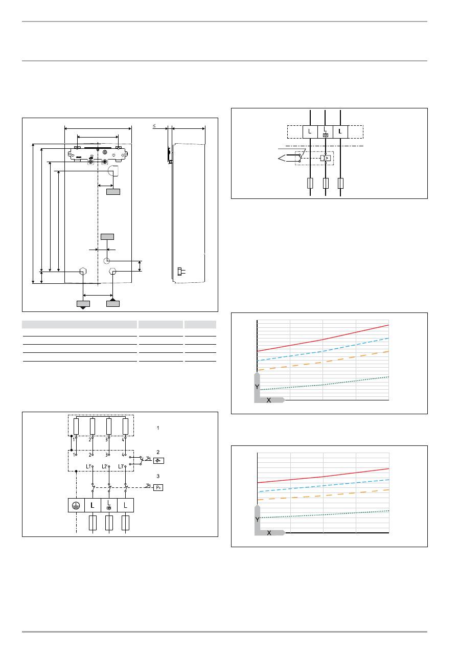
INSTALLATION Speci Ð cation 15. Specification
15.1 Dimensions and connections
b02
c01
c06
470
100
414
40
117
20
225
140
35
368
30
338
47
b03
D00000
2
3
6
0
9
b02 Entry electrical cables I
b03 Entry electrical cables II
c01
Cold water inlet
Male thread
G 1/2 A
c06 DHW
outlet
Male thread
G 1/2 A
15.2 Wiring
diagram
3/PE ~ 380 - 415 V
8
5
_0
2_0
2
_0
0
0
5
1 Bare wire heating system
2 High limit safety cut-out
3 Safety pressure limiter
Priority control with load shedding relay (LR 1-A)
See also chapter “Appliance description / Accessories”.
8
5
_0
2_0
2
_0
0
0
3_
2
1
1 Control cable to the contactor of the second appliance (e.g.
electric storage heater).
2 Control contact opens when switching the instantaneous
water heater on.
15.3 Mixed water volume / outlet volume
The values are relative to a rated voltage of 400 V. The mixed water
volume and outlet volume are subject to the available supply pres-
sure and the available mains voltage.
Available temperature approx. 38 °C in the shower, for hand wash-
ing, filling the bath etc.
6
10
14
4
5
6
7
8
9
10
11
12
13
14
15
4
3
2
1
84
_0
2_
0
2
_0
0
3
8
Outlet temperature approx. 55 °C for the kitchen sink and when
using thermostatic valves.
2
3
4
5
6
7
8
9
10
6
10
14
4
3
2
1
84
_0
2_
0
2
_0
0
3
9
X Cold water inlet temperature in °C
Y Mixed water volume / outlet volume in l/min
1 HDB-E 12 Si
2 HDB-E 18 Si
3 HDB-E 21 Si
4 HDB-E 24 Si
EN
GL
ISH
www.stiebel-eltron.com
HDB-E Si |
27
INSTALLATION Speci Ð cation
15.4 Application
areas
Specific electrical resistance and specific electrical conductivity
Standard
specification
at 15 °C
at 20 °C
at 25 °C
Resistance
Ω cm
≥ 1100
≥ 970
≥ 895
Conductivity
mS/m ≤ 91
≤ 103
≤ 112
Conductivity
μs/cm ≤ 910
≤ 1030
≤ 1120
15.5 Pressure
drop
Pressure drop at taps at flow rate of 10 l/min
Mono-lever mixer tap, approx.
MPa
0.04 - 0.08
Thermostatic valve, approx.
MPa
0.03 - 0.05
Hand shower, approx.
MPa
0.03 - 0.15
Sizing the pipework
When calculating the size of the pipework, a pressure drop for the
appliance of 0.1 MPa is recommended.
15.6 Fault
conditions
In case of faults, loads up to a maximum of 95 °C at a pressure of
1.2 MPa can occur temporarily in the installation.
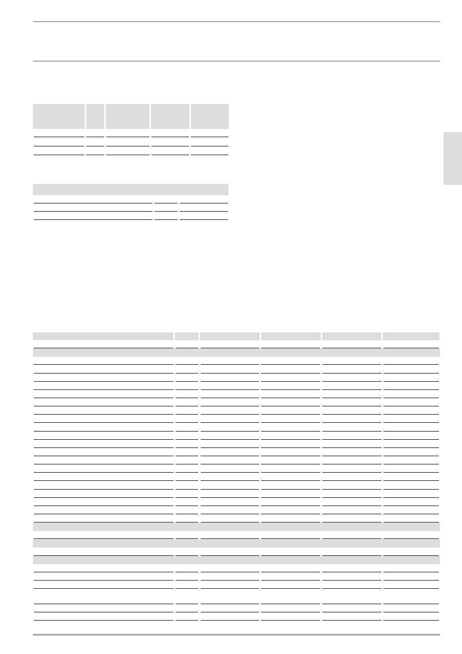
15.7 Data
table
HDB-E 12 Si
HDB-E 18 Si
HDB-E 21 Si
HDB-E 24 Si
232003
232004
232005
232006
Electrical data
Rated output 1
kW
11.0
18
21
24
Rated voltage 1
V
400
400
400
400
Rated current 1
A
16
26
31
35
Fuse 1
A
16
25
32
35
Rated output 2
kW
10.1
16.2
19
21.7
Rated voltage 2
V
380
380
380
380
Rated current 2
A
15.4
24.7
29.5
33.3
Fuse 2
A
16
25
32
35
Rated output 3
kW
11,5
19,4
22,6
25,8
Rated voltage 3
V
415
415
415
415
Rated current 3
A
16
27
32,2
36,3
Fuse 3
A
16
32
32
40
Phases
3/PE
3/PE
3/PE
3/PE
Frequency
Hz
50/-
50/-
50/-
50/-
Max. mains impedance Zmax to DIN EN 61000-3-11
Ohm
0.33
0.33
Conductivity at 15 °C
mS/m
90.9
90.9
90.9
90.9
Specific resistance (≤25 °C)
Ohm cm
1100
1100
1100
1100
Connections
Water connection
G 1/2 A
G 1/2 A
G 1/2 A
G 1/2 A
Application limits
Max. permissible pressure
MPa
1
1
1
1
Values
Max. permissible inlet temperature
°C
25
25
25
25
On
l/min
> 2.3
> 2.3
> 2.3
> 2.3
Flow rate for pressure drop
l/min
3.1
5.2
6.0
6.9
Pressure drop at flow rate
MPa
0.07 (0.02 without
DMB)
0.08 (0.06 without
DMB)
0.10 (0.08 without
DMB)
0.13 (0.1 without
DMB)
Flow rate limit at
l/min
4
7.5
7.5
8.5
DHW delivery
l/min
5.5
9.0
10.5
12
28
| HDB-E Si
www.stiebel-eltron.com
INSTALLATION Speci Ð cation
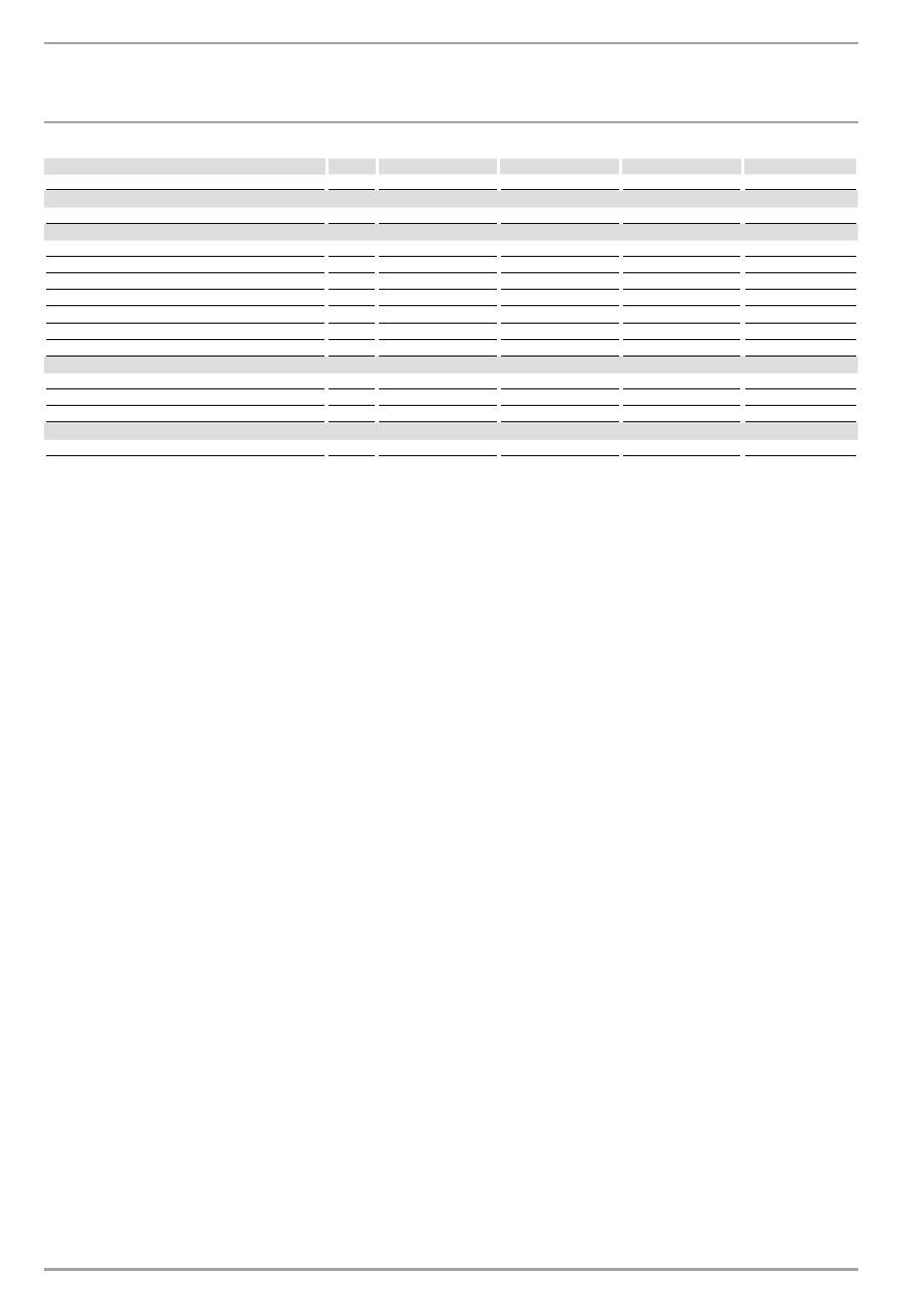
HDB-E 12 Si
HDB-E 18 Si
HDB-E 21 Si
HDB-E 24 Si
Delta T if presented
K
28
28
28
28
Hydraulic data
Nominal capacity
l
0.4
0.4
0.4
0.4
Versions
Temperature setting
°C
55
55
55
55
Safety category
1
1
1
1
Insulation block
plastic
plastic
plastic
plastic
Heating system
bare wire
bare wire
bare wire
bare wire
Cap and back panel
plastic
plastic
plastic
plastic
Colour
white
white
white
white
IP rating
IP25
IP25
IP25
IP25
Dimensions
Height
mm
470
470
470
470
Width
mm
225
225
225
225
Depth
mm
117
117
117
117
Weight
Weight
kg
3.6
3.6
3.6
3.6

EN
GL
ISH
www.stiebel-eltron.com
HDB-E Si |
29
WARRANTY | ENVIRONMENT AND RECYCLING Warranty
The warranty conditions of our German companies do not
apply to appliances acquired outside of Germany. In countries
where our subsidiaries sell our products, it is increasingly the
case that warranties can only be issued by those subsidiaries.
Such warranties are only granted if the subsidiary has issued
its own terms of warranty. No other warranty will be granted.
We shall not provide any warranty for appliances acquired in
countries where we have no subsidiary to sell our products.
This will not affect warranties issued by any importers.
Environment and recycling
We would ask you to help protect the environment. After use,
dispose of the various materials in accordance with national
regulations.
