HP Designjet 10000s Printer series: инструкция
Раздел: Бытовая, кухонная техника, электроника и оборудование
Тип: Принтер
Инструкция к Принтеру HP Designjet 10000s Printer series
Оглавление
- I Введение
- II Описание изделия
- III Техника безопасности III 1 Общие указания III 2 Надлежащее использование III 3 Указания к знакам и символам
- III 4 Предупреждения
- III 5 Предупреждения, на которые необходимо обратить внимание при обслуживании III 6 Защитное оборудование
- Содержание
- 1 Описание монтажа и функции 1.1 Транспорт на деревянном поддоне
- 1.2 Распаковка и монтаж 1.3 Содержание ящика
- 1.4 Подключение принтера 1.5 Подключение СОВ к сетевому напряжению 1.6 Описание принципа действия
- 2 Эксплуатация 2.1 Условия эксплуатации 2.2 Эксплуатация
- 2.3 Тестовый режим работы
- Обозначение № продукта
- Рис. 1 Рис. 2 Рис. 3
- Рис. 4 3.3.2 Монтаж нового/новых фильтра(ов) Рис. 5 Рис. 6 Рис. 7
- 3.4 Ввод кода сменного фильтрующего элемента 3.4.1 Система очистки воздуха для принтера HP Designjet 8000s
- 3.4.2 Система очистки воздуха для принтера HP Designjet 9000s/10000s 305
- 4 Утилизация
- 5 Устранение неисправностей
- 6 Законодательные положения
- 5. Применение в системе очистки воздуха для принтеров HP Designjet 9000s/10000s
- B. Ограничение ответственности C. Местное право (действующее право)

Index Page
1. English (GB) HP Designjet 8000s / 9000s/10000s Air Purifier System 3
2. German (D) HP Designjet 8000s / 9000s/10000s Luft-Reinigungssystem 29
3. Spanish (E) Sistema de purificación de aire 55
HP Designjet 8000s / 9000s/10000s
4. Portuguese (P) Sistema de Purificação de Ar 81
HP Designjet 8000s / 9000s/10000s
5. French (F) HP Designjet 8000s / 9000s/10000s 107
Système de nettoyage d'air
6. Italian (I) Sistema di depurazione dell'aria 133
HP Designjet 8000s / 9000s/10000s
7. Turkish (TR)
HP Designjet 8000s / 9000s/10000s 159
Hava Temizleme Sistemi
8. Polish (PL) System oczyszczania powietrza 185
HP Designjet 8000s / 9000s/10000s
9. Hungarian (H) HP Designjet 8000s / 9000s/10000s Légtisztító rendszer 211
10. Greek (GR)
Óýóôçìá ÊÊáèáñéóìïý ÁÁÝñá
237
HP DDesignjet 88000s // 99000s/10000s
11. Czech (CZ) Cistic vzduchu HP Designjet 8000s / 9000s/10000s 263
12. Russian (RUS) HP Designjet 8000s / 9000s/10000s 289
Система очистки воздуха
13. Korean (ROK)HP Designjet 8000s / 9000s/10000s 315
14. Chinese (VRC) HP Designjet 8000s / 9000s/10000s 341
15. Taiwanese(RC) HP Designjet 8000s / 9000s/10000s 367
1

2 User´s Guide

HP DDesignjet 99000s/10000s AAir PPurifier SSystem
HP DDesignjet 88000s AAir PPurifier SSystem
User´s GGuide
3

I Introduction
This User's Guide is an essential help for the successful and safe operation of the HP Designjet
9000s/10000s Air Purifier System and HP Designjet 8000s Air Purifier System - referred to in
this document as APS.
The operating instructions contain important information for operating the APS safely, properly
and economically. Following these instructions can help to avoid dangerous situations, repair
costs and reduce downtimes and improve the reliability and extend the useful life of the APS.
The operating instructions must at all times be kept available near the APS.
The information contained in this document is subject to change without notice.
Hewlett-Packard makes no warranty of any kind with regard to this material, including, but not
limited to, the implied warranties of merchantability and fitness for a particular
purpose.
Hewlett-Packard shall not be liable for errors contained herein or for incidental or consequenti-
al damages in connection with the furnishing, performance, or use of this material. No part of
this document may be photocopied or translated to another language without the prior written
consent of Hewlett-Packard Company.
4 User´s Guide
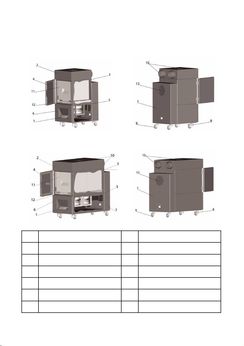
II Product ddescription
HP DDesignjet 88000s AAir PPurifier SSystem
HP DDesignjet 99000s/10000s AAir PPurifier SSystem
Transparent display, membrane
1
2 Casing cover
keyboard
3 Filter casing 4 Service flap on the filter housing
5 Fan housing 6 Fan & electronics cover
7 Sound absorption module 8 Castor with brake
9 Castor 10 Intake stub
HP Designjet APS 8000s /
11
12 Filter lifting mechanism
9000s/10000s Filter
13 Exhaust grid
5HP Air Purifier System
III Safety
III 11 General iinformation
The APS is built in accordance with state of the art technology and adherence to safety rules.
Nevertheless, during use there may be dangers to the user or a third parties if it is not used for
the purpose for which it was intended, and not properly maintained.
III 22 Use aas iintended
The APS may only be operated with the HP printers for which it is designed.
The work area where the HP Designjet 8000s or 9000s/10000s printer is used must be ade-
quately ventilated. The APS is not a substitute for ventilation of the work area.
The APS is not intended to be used as a substitute for adequate ventilation of the work area.
The APS removes
v
olatile
o
rganic
c
ompounds (VOC's ) released inside the printer during ope-
ration, but prints that are drying and being stored also release VOC's. The APS only reduces
the release of volatile organic compounds in the work area from the printer and it is not inten-
ded under any circumstances to be used in closed room without ventilation.
Any other use other than direct connection to an HP Designjet 8000s and 9000s/10000s prin-
ter is not considered to be proper use of the APS.
This also applies for unauthorized modifications to the APS. In particular in the case of replace-
ment filter elements purchased from third parties, there is no guarantee that performance will
meet HP specifications.
Proper use includes compliance with the information:
- on safety,
- on operation and
- on maintenance,
as described in this user's guide
III 33 Information oon ssigns aand ssymbols
The following designations or symbols for safety information and particularly important details
are used in these operating instructions:
Warning!
Failure to follow the guidelines marked with this symbol could result in serious perso
nal injury or death
Caution!
Failure to follow the guidelines marked with this symbol could result in minor personal
injury or damage to the product.
Note
Additional information for a safe, proper and efficient handling of the APS.
• Work and/or operating steps are marked with the large reference point. The
steps are to be executed in the order from top to bottom!
– Lists are marked with the dash.
All information should be complied with, for the proper use of the APS. Please be sure all ope-
rators of the APS are completely familiar with information in this manual.
Information and symbols directly attached to the APS, such as warning signs, warning stickers
component part markings etc must be observed.
The information and symbols directly attached to the APS may not be removed and must be kept
in a completely readable condition.
6 User´s Guide
III 44 Warnings
– Do not immerse the APS in water or other liquids.
– Do not use the APS in areas with very high concentration of dust.
– Do not use the APS outdoors.
– Use only the proper power cables supplied by HP with the APS.
– Use the power supply voltage specified on the nameplate. Doing otherwise may cause
fire or electric shock.
– Do not connect multiple loads to one power outlet. Doing so may cause fire or electric
shock.
– Do not disassemble or remodel the APS. Do not repair the APS by yourself. Doing so
may cause fire, electric shock, or other accidents.
– Do not remove the screwed covers, because they content high-voltage. Careless remo
val might result in electric shock or burn.
– See the label on the fan & electronics cover (Number 6 in APS description).
– Do not disconnect or connect the power cable with wet hands. Doing so may lead to
electric shock.
– Turn the APS OFF and unplug he power cable from the power outlet if there is smoke
or an unusual smell coming from the APS.
– Do not install or operate the APS within 8 meters (25 feet) of open flames, sparks, or
other sources of ignition.
– Always use genuine HP replacement Filter Elements. These have been designed for reli
able filtration and qualified to work with your Designjet 8000s or 9000s/10000s prin-
ter. Using non-HP Filter Elements may result in ineffective filtration of volatile organic
compounds and pose health and safety hazards.
– Be sure all operators are trained in the use of emergency equipment such as eye wash
stations and fire extinguishers and know where they are located.
– Used filters capture an organic solvent (ethylene glycol monobutyl ether acetate,
CAS No. 112-07-2) and other chemicals from ink vapors. When disposing used filter
cartridges it is your responsibility to observe all local, state, and federal regulations rela
ted to the handling, use, storage, and disposal of organic solvents.
– Do not disassemble the filter elements.
– If any liquid is present on used filter elements, avoid contact with skin, eyes, and
clothing. Handle the used filters while wearing latex or Nitrile ® gloves. Immediately
wash skin that has come in contact with liquids with soapy water. Remove any clothing
soaked with liquids from contact with skin. If liquid comes in contact with eyes, use an
approved eye wash station and consult a doctor if necessary. If an approved eye wash
station is not available, flush eyes with cold water and contact a doctor if necessary.
– The liquid captured by the filters is combustible. Do not use or store used filters within 8
meters (25 feet) of open flames, sparks, or other sources of ignition.
– Do not smoke within 8 meters (25 feet) of the APS.
– Keep used filter cartridges out of the reach of children.
– Do not obstruct air inlets and outlet.
7HP Air Purifier System

III 55 Warnings ffor mmaintenance
The APS must be switched off for maintenance, and be secured against being switched on again
unexpectedly, by:
• the APS must be switched off at the ON/OFF switch and then
• the power plug must be removed from the wall power socket.
Do not put your hand in the cover grid of the fan during fitting, assembly or service work.
– After switching off /shutdown of the APS wait until the fan stops.
To avoid electric shocks do not open any electrical parts and casing and covers.
It is recommended to use protective gloves (disposable gloves made of polyethylene, latex or
Nitrile®) before carrying out the filters replacement and/or the suction hoses.
Replace filter elements at the stated intervals. Always tightly rescrew screw connections
loosened.
Do not use any aggressive agents or cleaning agents which contain solvents. Use lint-free
cleaning cloths.
Only use mild water-based cleaning agents. Do not use any organic solvents, as there is a risk
of fire and explosion!
Ensure ssafe aand eenvironmentally-ffriendly ddisposal oof mmaterials aand ssupplies.
III 66 Protective eequipment
The APS is equipped with safety interlocks to protect the user and is constructed and produced
in accordance with state-of-the-art- technology to meet operational safety regulations. In order
to ensure safe and environmentally-responsible operation, the following safety features have
been installed:
– The fan is secured by a protective plate or grid, which may only be removed using tools.
– All elements of the control systems will move into a safe status for operators, APS and
the environment in the case of power cut or reported disturbances. An unexpected
restart is not possible after this.
– All electrical parts carry the CE mark for low voltage and/or EMV.
– A potential compensation (Ø > 1.5 mm²) of all conducting components is installed to
ground the APS.
– The APS is designed according to protective type IP 20.
8 User´s Guide

Index
I Introduction 4
II Product ddescription 5
III Safety 6
III 1 General information 6
III 2 Use as intended 6
III 3 Information on signs and symbols 6
III 4 Warnings 7
III 5 Warnings for maintenance 8
III 6 Protective equipment 8
1 Installation && FFunction DDescription 10
1.1 Transport on wooden pallet 10
1.2 Unpacking and installation 11
1.3 Box content 11
1.4 Connection of the printer 12
1.5 Power on the APS 12
1.6 Function description 12
2 Operation 13
2.1 Operating conditions 13
2.2 Operation 13
2.3 Test operation 14
3 Maintenance 15
3.1 General information 15
3.2 Routine maintenance work 15
3.3 Replacement of filters 15
3.3.1 Removal of the old filter(s) 16
3.3.2 Insert the new filter(s) 17
3.4 Enter the code of the new replacement filter 18
3.4.1 HP Designjet 8000s Air Purifier System 18
3.4.2 HP Designjet 9000s/10000s Air Purifier System 19
4 Disposal 20
5 Troubleshooting 21
6 Legal iinformation 22
7 Regulatory nnotices 25
7.1 Regulatory model number 25
7.2 Regulatory statements 25
8 Declaration oof cconformity 27
9 Technical ddata 28
9HP Air Purifier System
1 Installation && FFunction DDescription
1.1 Warnings ffor mmaintenance
The APS is delivered upright on a wooden pallet according to the IPPC standard. The following
industrial trucks are permitted for transporting the wooden pallets:
– Fork lift trucks and
– Fork stacker lift trucks.
Do not drop the APS during handling.
Secure the wooden pallets with the upright APS during transport to prevent the APS from falling
over.
Observe the applicable accident prevention and labour safety regulations.
You must observe the information on the packaging.
The APS or the wooden pallet with the APS is to be secured on the transport vehicle against slip-
ping and falling over.
Warning!
If the wooden pallets are not secured properly the APS may fall down and cause seri-
ous injury or death.
Only use suitable hoisting equipment and securing means!
The driver must be authorized to steer the industrial truck.
Drive between the spans of the wooden pallet using the fork lift truck.
Observe the following information for transporting the APS:
– The fork lift truck must be permitted for the total weight of the wooden pallets with
upright APS.
– Weight of the complete HP Designjet 8000s APS, net: approx. 60 kg
– Weight of the wooden pallet + 8000s APS + packaging: approx. 76 kg
– Weight of the complete HP Designjet 9000s/10000s APS, net: approx. 95 kg
– Weight of the wooden pallet + 9000s/10000s APS + packaging:approx. 113 kg
– The length of the forks must be at least: 1,000 mm
– The transport crates must be tightly fixed to the industrial truck in order to avoid
them falling over.
It is to be prevented that the APS and the hoisting platform of the industrial truck come into
contact:
– For this purpose wedge a distance wood or cardboard between the packaging of
the APS and the platform.
– Avoid hard knocks when setting down the APS.
– All persons must leave the working area of the industrial truck before lifting the APS.
10 User´s Guide
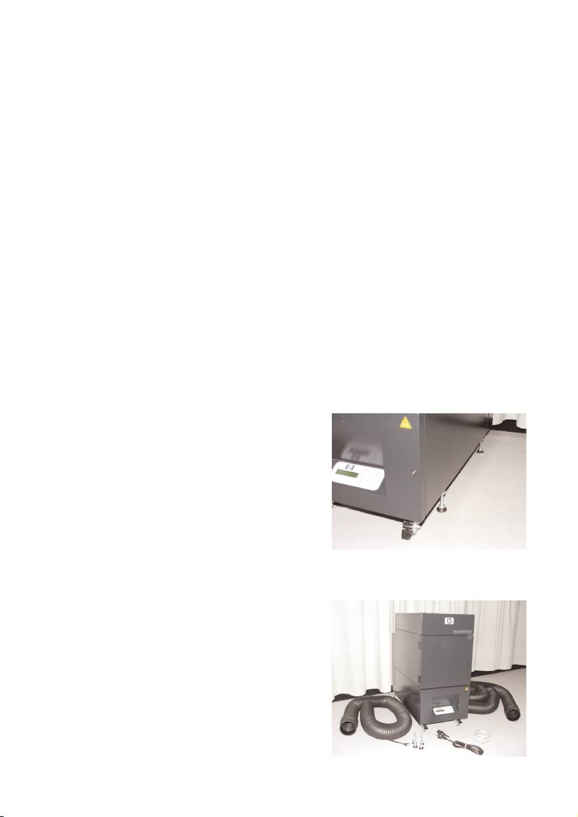
1.2 Unpacking aand iinstallation
Note:
When the APS is installed, allow adequate space for exhaust hoses from the printer. Lo-
cate these hoses and the APS so that they do not pose a trip hazard or interfere with the opera-
tion of the printer such as loading and unloading media, replacing Ink Cartridges, inspecting
and replacing the Waste Ink Bottle.
Note:
Allow adequate space around the APS to remove and replace the filter elements.
Note:
Do not install the APS in an area where it receives direct airflow from air conditioners,
heaters, or ventilators.
Note:
Proceed as follows when unpacking and installing the APS:
– Do not lift the APS off the wooden pallet or remove from the transport packaging
until you reach the place of installation. Carefully remove the packaging.
– Check the completeness of the delivery based on the packing list. Also check the
complete delivery for external damages, such as may have occurred in transit.
– Move the APS on its casters until you reach the place of installation
– Install the APS on a level, firm surface.
– Secure the APS against unintended rolling by pressing the brakes on the casters.
– The APS must be placed in such a way that the exhaust grid can lead the filtered
air back into the working room.
– Secure the APS with placing of the adjustment feet to prevent the APS for uninten-
tional tilting (according EN 60950-1 test of stableness) to the side. In the bottom of
the APS housing, 4 nuts are fastened for placing of the adjustment feet. To be able
to screw the adjustment feet into the 4
nuts it is necessary to remove the 4 exi-
sting screws M10.
The positioning of the adjustment feet has
to be according to the underground in
such a way that the APS is placed on an
even and firm underground and the exi-
sting wheels are not relieved.
1.3 Box ccontent
When you receive the APS please check in detail the box content. The regular scope of delivery
includes:
– APS, complete (with built-in filter ele-
ments);
– Hose set I (4 m hose, 2 m hose; respec-
tively incl. connection stubs and clamping
hoses)
–Power cord
You can receive more than one, please
choose the proper for your need
– 4 adjustment feet M10, length: 85 mm
– 1 open-end wrench
11HP Air Purifier System
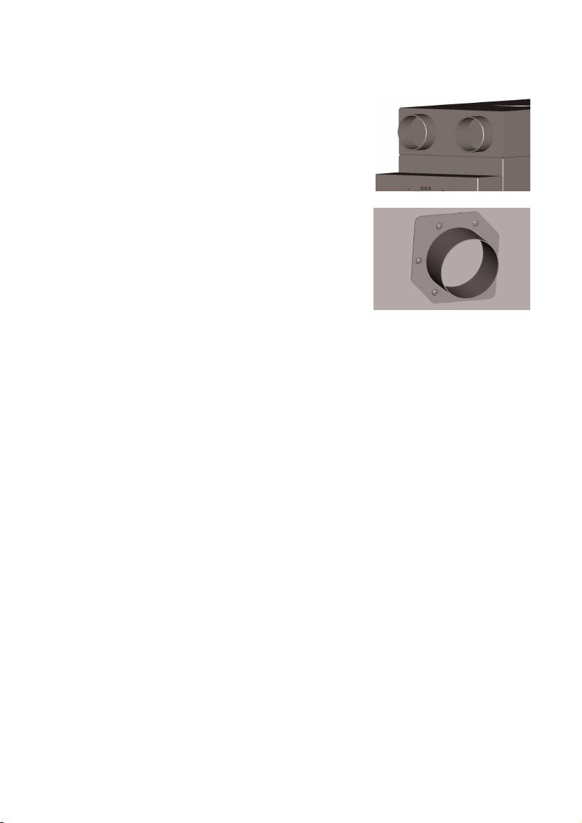
1.4 Connection oof tthe pprinter
The APS is installed to the printer connecting two hoses as
follows:
– Take the hoses and plug the end stubs on the
intake ports of the APS
Note:
The two hoses are fitted with a stub at one end.
– The other end of the hose is pushed through the
exhaust attachment flange of the printer and
mounted with a clamping hose.
Note:
The printer has on the left and right side respectively two
exhaust attachment flanges.
1.5 Power oon tthe AAPS
Connect the APS as follows:
– Insert the plug of the power cable into the socket.
Ensure that the supply voltage matches that posted on the unit.
– Finally check again all connection for accuracy and tight fit.
The APS may be put into operation after all hose pipes have been connected and the connec-
tion checked.
1.6 Function ddescription
Suction hoses are connected directly between exhaust ports on the HP Designjet 8000s or
9000s/10000s printers and the APS.
The APS is switched on at its membrane keyboard.
Air containing volatile organic compounds from HP low-solvent inks released inside the HP Des-
ignjet 8000s or 9000s/10000s printers is removed through the hoses and brought into the fil-
ter casing and filter elements.
The filter element consists of the following filter levels:
– Pre-filter mat and activated carbon filter.
Purified air with volatile organic compounds trapped in the filter elements is drawn out by the
fan below the filter element and then passes through the exhaust grid in the sound absorption
module attached at the rear.
12 User´s Guide
2 Operation
2.1 Operating cconditions
The APS must be operated in a vibration-free, dry and as far as possible dust-free location.
The APS must be operated in a work area receiving adequate ventilation.
Under no circumstance operate the APS in a closed room without ventilation.
The air temperature must be in a temperature range between + 5 °C and + 35 °C.
The relative humidity in the air may not exceed 70 %. Condensation from humidity on the sur-
faces of the APS must be avoided.
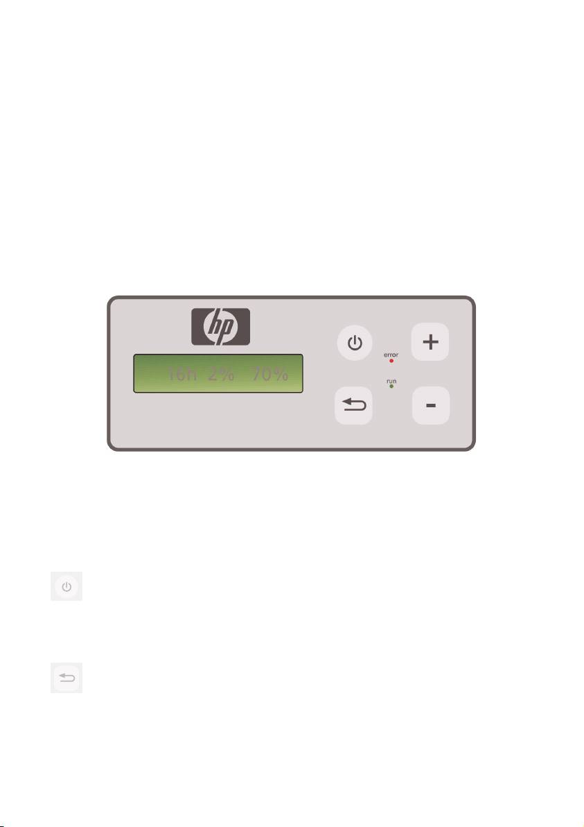
2.2 Operation
The APS is controlled via its membrane control panel with transparent display ( Fig. 1). All the
functions of the APS will be controlled from this panel.
Figure1: membrane control panel with transparent display
The basic setting will be displayed in the transparent display when the machine is switched on:
– On the left the total hours of operation on the installed filter element.
– In the middle the actual filter saturation given as a percentage of full capacity.
– On the right: fan speed as a percentage of the maximum. The minimum value is
set to 20%.
You will find the following control elements on the membrane control panel of the APS:
ON/OFF button
The ON/OFF button is used for switching the APS on and off. When switched on
you can hear the fan start and the air will be extracted from the printer.
If you change the values (e. g. fan speed), then these settings will be saved when
the unit is switched off. When it is switched on again the APS will continue to ope-
rate with these settings.
ENTER bbutton
This button is only to be used by your service technician for control work and adjust-
ments to the electronic control of the APS (e.g. after replacement of the filter ele-
ments).
If nothing is entered/changed for several seconds, the display automatically returns
to the basic setting.
13HP Air Purifier System

Button ““+”
This button is used for increasing the fan speed in %-steps. You can notice the
increase in the number of revolutions by the increase in the level of noise. The
changed value will be taken over directly.
Button ““–”
This button is used for reducing fan speed in %-steps. You can notice the reduction
in speed by the reduction in the level of noise. The changed value will be taken
over directly.
LED ““Error” ((red)
If the red LED lights up the filter element is saturated and must be replaced.
LED ““Run” ((green)
Shows that the APS is switched on. If the LED Run blinks green, it means the filter
element must be replaced within 100 additional operating hours.
2.3 Test ooperation
Note
Carry out the test operation if you have just purchased the APS and would like to
become familiar with the functions.
Carry out the test of the APS as follows:
• First check all connections on the APS that they are correct and fitted tightly.
• Switch the APS on via the membrane keyboard using the button ON/OFF.
• Increase the fan speed, by touching the button "+" and keeping it pressed
down. You can notice the increase in the fan speed by the increase in the
level of noise. At the same time, the right % appears in the transparent
display.
• Reduce the fan speed, by touching the button "– " and keeping it pressed
down. You can notice the reduction in speed by the reduction in the level of
noise. In addition to this, the right %-appears in the transparent display
(Minimum 20 %).
• Switch the APS off via the membrane keyboard using the button ON/OFF. If
the APS operates correctly, then the APS is ready for normal operation.
14 User´s Guide
3 Maintenance
3.1 General iinformation
Warning!
Used filters capture an organic solvent (ethylene glycol monobutyl ether acetate, CAS
No. 112-07-2) and other chemicals from ink vapors. When disposing used filter car--
tridges it is your responsibility to observe all local, state, and federal regulations rela-
ted to the handling, use, storage, and disposal of organic solvents.
Warning!
You must remove the power supply cable on the APS during cleaning and service work.
Note:
Please also follow the safety instructions in section III Safety.
3.2 Routine mmaintenance wwork
You must inspect the accessible areas of the APS daily for damage and assess the APS for pro-
per operation
Caution!
– Labels and control elements or warning signs may become illegible through un--
avoidable dirt deposits. This can lead to faulty operation, which may cause a safety
hazard.
– It is recommended to clean control elements, displays and warning stickers once a
week removing accumulated dust and other dirt by wiping with a clean, damp
cloth. Avoid using an excessively wet cloth that may release liquids into the APS.
– Avoid the use of solvent cleaners, which may attack elements of the keypad, dis
play, gaskets, or paint. Only water-based cleaners or soapy water are recommen
ded.
– Do not allow liquids to spill into or penetrate into the APS.
3.3 Replacement oof ffilters
The filter elements must be replaced after an interval period of 800 operating hours. The dis-
play of the filter contamination in the transparent display shows in this case 100 % and the red
LED (Error) will light permanently. All activated carbon filters will become full at different speeds
depending on type of use, and they should be replaced between 700 and 800 operating
hours, and no later than 800 hours under any circumstance. For ordering new filters:
15HP Air Purifier System
Designation
Product NNumber
HP Designjet 8000s / 9000s/10000s APS Filter
Q6679 A
(HP Designjet 8000s Air Purifier system,
1x filter element required)
(HP Designjet 9000s/10000s Air Purifier system,
2x filter elements required )
Note
The green LED blinks after an interval period of 700 operating hours as an indication
to order new filters, and also this means the filter elements must be replaced within
100 additional operating hours.
Caution!
When removing or inserting the filter elements it is recommended to use protective glo-
ves (disposable gloves made of polyethylene, latex or Nitrile®) before carrying out the
filters replacement and/or the suction hoses.
With the system "HP Designjet 8000s Air Purifier System" one filter element is used in the filter
unit. With the system "HP Designjet 9000s/10000s Air Purifier System" two filter elements are
placed behind each other in the filter unit. With the filter system "HP Designjet 9000s/10000s
Air Purification System" always replace both filter elements at the same time.
You should proceed as follows when replacing the filter:
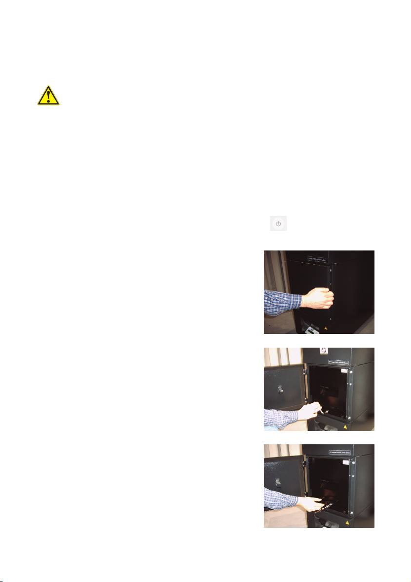
3.3.1 Removal oof tthe oold ffilter(s)
• Switch off the APS at the membrane keyboard using the button.
• Secure the APS against being switched on again unexpectedly, by removing
the power cable from the wall power socket.
• Grasp the rear right of the service flap (Fig.1) with
one hand and open this to the left.
Note:
You must overcome the resistance of the latch!
• Remove the offset screwing key from the intake.
• Slacken the sealing lifting mechanism by turning the
adjusting screw (Fig. 2) using the offset screwing key.
Turn the adjusting screw until the filter element is at
the bottom and can be shifted freely.
• Release the filter locking (Fig. 3)
16 User´s Guide
Figure 1
Figure 2
Figure 3
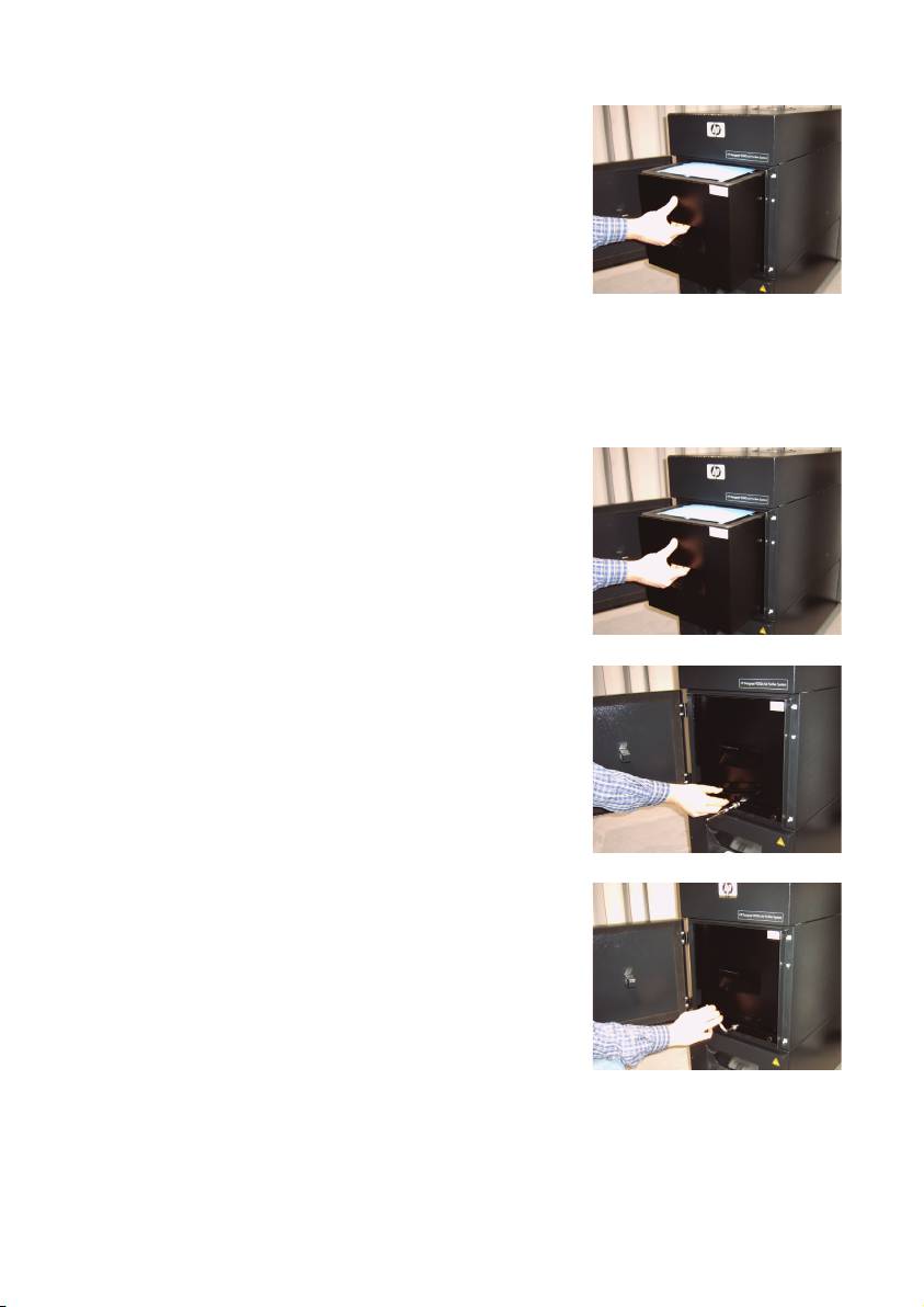
• Grasp the handle of the filter element and pull the
filter element out of the filter housing (Fig. 4) while
it stands securely in the filter housing. You can secu-
rely grasp under filter element with both hands and
then place it down carefully.
Note
: Each filter element weights approx. 16 kg.
Figure 4
Immediately dispose of the used filter element. Used filters capture an organic solvent (ethylene
glycol monobutyl ether acetate, CAS No. 112-07-2) and other chemicals from ink vapors. When
disposing used filter cartridges it is your responsibility to observe all local, state, and federal
regulations related to the handling, use, storage, and disposal of organic solvents.
3.3.2 IInsert tthe nnew ffilter(s)
Please, proceed as follows:
• Remove the new filter element(s) from the packaging.
• Store the enclosed flyer with the code in a safe place.
You will need this later to reset the service interval.
• Push the filter element(s) (Fig. 5) into the filter housing
up to the stop. The surrounding gasket on the filter
element must be at the top, and the handle of the fil-
ter element must point towards the service opening.
Figure 5
• Put the filter locking. (Fig.6)
Figure 6
• Tighten the sealing lifting mechanism (Fig. 7) by tur-
ning the adjusting screw until it is completely tight.
• Insert the screwing key into the intake again.
• Close the service door until the latch engages.
Figure 7
Note:
Always pay attention that the surrounding gasket on the filter element(s) and on the pre-filter tray
at the top is pushed into the stop, and the adjusting screw is completely tight. Otherwise, this
can lead to leakages and the extracted gases and dust will not be filtered properly.
17HP Air Purifier System

3.4 Enter tthe ccode oof tthe nnew rreplacement ffilter
In order to reset the service interval one code must be entered with the HP Designjet 8000s Air
Purifier System. Two codes are necessary with the HP Designjet 9000s/10000s Air Purifier
System. The code input for the 8000s and 9000s/10000s is explained in the following chap-
ters.
3.4.1 HHP DDesignjet 88000s AAir PPurifier SSystem
After replacing the filter element the service interval must be reset using the code. The following
steps must be carried out in the following order:
Switch the APS on at the membrane keyboard using the button ON/OFF. When it
switches on you will hear the fan and it will begin to extract the gases.
If "service filter" is shown in the display you must press the button "+" or "– " to
suppress this fault report.
By pressing the button ENTER the programme name is displayed.
By pressing the button ENTER again "
code 1: 00000
" is displayed.
Now you can enter the code using these buttons. The code is on the flyer which is
enclosed with the new filter element.
By pressing the button ENTER the actual code is saved.
If this code has been entered correctly the value for the filter contamination (middle indication
in the display) is reset to "0%" and the blinking green (run) and red ( error ) LEDs will be reset.
Note
The code is on the flyer that is enclosed with the new filter element.
18 User´s Guide

3.4.2 HP DDesignjet 99000s/10000s AAir PPurifier SSystem
After replacing the filter element the service interval must be reset using the code. The following
steps must be carried out in the following order:
Switch the APS on at the membrane keyboard using the button ON/OFF. When it
switches on you will hear the fan and it will begin to extract the gases.
If "service filter" is shown in the display you must press the button "+" or "– " to
suppress this fault report.
By pressing the button ENTER the programme name is displayed.
By pressing the button ENTER again "
code 1: 00000
" is displayed.
Now you can enter the code using these buttons. The code is on the flyer which is
enclosed with the new filter element.
By pressing the ENTER the actual code is saved and "
code 2: 00000
" is
displayed.
Now you can enter the code using these buttons. The code is on the flyer which is
enclosed with the new filter element.
By pressing the ENTER the actual code is saved.
If this code has been entered correctly the value for the filter contamination (middle indication
in the display) is reset to "0%" and the LED`s which may be lit or blinking extinguishes.
Note
– With the HP Designjet 9000s/10000s Air Purifier System a "
code 2: 00000
" the code
from the second filter element also must be entered.
– If the code 2 was not entered correctly, then also the code 1 must be entered again.
19HP Air Purifier System

4 Disposal
It is the APS owner's responsibility to ensure that waste is disposed of in accordance with all lo-
cal, state and federal regulations.
There are registered waste management companies that have been authorized by local autho-
rities to manage waste collection and disposal and that will manage waste management and
disposal on your behalf.
We recommend that you contact your local authorities for a list of authorized companies, or you
can search for the nearest authorized waste disposal company on the World Wide Web.
Make sure that any waste disposal company you engage for this task is able to provide you with
the necessary documentation proving their authority to manage and dispose of waste legally.
You will be legally responsible for failing to dispose of waste according to local, state and fe-
deral legislation.
When you have established an authorized waste management company, they will need to know
the type of chemical that requires disposal and you will need to determine the type of agree-
ment that best meets your requirements.
They will need to know the common name or chemical CAS number of the main solvent found
in the printing supplies. Used filters capture an organic solvent (ethylene glycol monobutyl ether
acetate, CAS No. 112-07-2) and other chemicals from ink vapors that can be obtained on the
Material Safety Data Sheets (MSDS) available for all supplies at:
http://www.hp.com/hpinfo/globalcitizenship/environment/productdata/index.html
The APS captures organic solvents, and after removal and disposal of the filter elements, some
solvents may remain in the unit and hoses connected to the printer. If the APS is to be perma-
nently removed from operation, it is your responsibility to observe all local, state, and federal
relations related to the disposal of the components and materials of the APS.
20 User´s Guide
