Trimble Outdoors HV101: инструкция
Раздел: Оптика
Тип:
Инструкция к Trimble Outdoors HV101
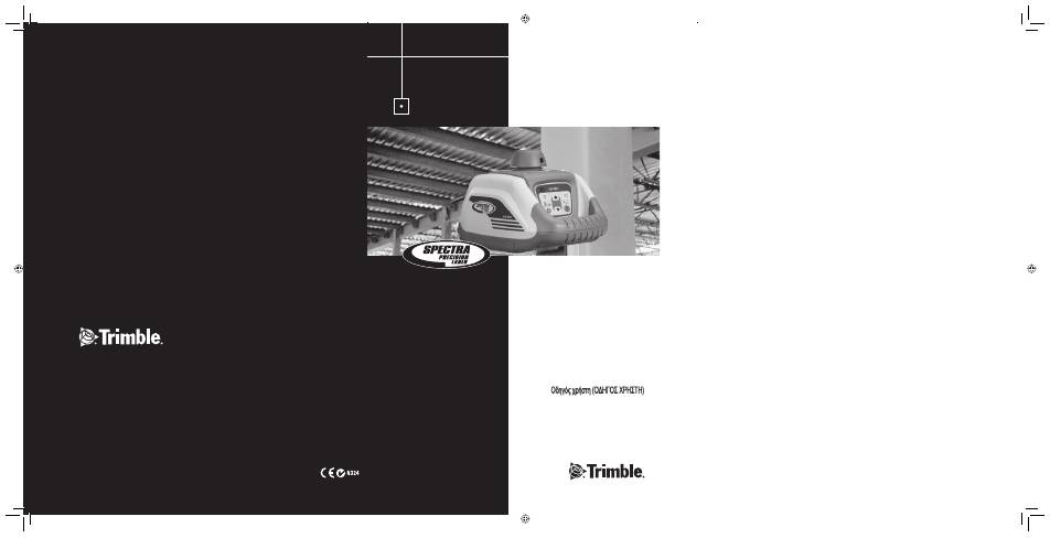
HV101
User Guide
Bedienungsanleitung
Manuel de l´utilisateur
Guida per l´uso
Gúia del usuario
Gebruikershandleiding
Operatörshandbok
Betjeningsvejledning
Guia do Usuário
Bruksanvisning
Käyttäjän opas
Руководство
пользователя
Trimble Construction Division
5475 Kellenburger Road
Dayton, Ohio 45424-1099
U.S.A.
+1-937-245-5600 Phone
www.trimble.com
www.trimble.com
© 2008, Trimble Navigation Limited. All rights reserved.
PN Q103740 (01/08)
© 2008, Trimble Navigation Limited. All rights reserved
PN Q103740 (rev. A) (01/08)
Trimble Construction Division
5475 Kellenburger Road
Dayton, Ohio 45424-1099
U.S.A.
+1-937-245-5600 Phone
080309_00_HV101_Umschlag.indd 1
080309_00_HV101_Umschlag.indd 1
26.02.2008 9:05:04 Uhr
26.02.2008 9:05:04 Uhr
Q103740 (rev. A) (01/08)
080309_00_HV101_Umschlag.indd 2
080309_00_HV101_Umschlag.indd 2
26.02.2008 9:05:06 Uhr
26.02.2008 9:05:06 Uhr
5
• Use of this product by people other than those trained on this product may result in exposure to hazardous
laser light.
• Do not remove warning labels from the unit.
• The HV101 is Class 3A/3R (< 5mW, 600 ... 680 nm).
• Never look into the laser beam or direct it to the eyes of other people.
• Always operate the unit in a way that prevents the beam from getting into people‘s eyes.
Thank you for choosing one of the Spectra Precision Lasers from the Trimble family of precision horizontal/
vertical lasers.
The HV101 is a simple-to-use laser that allows you to take accurate horizontal/vertical measurements, 90°-
and plumb point transfer.
TABLE OF CONTENTS
FOR YOUR SAFETY
5
COMPONENTS
6
How to Use the Laser System
6
Powering the Laser
6
Laser Setup
6
Turning On/Off the Laser
6
Activating/Deactivating Standby Mode
7
Using the Rotation Mode
7
Using the Pointing Mode
7
Using the Scan Mode
7
Using the Manual Mode
7
Using the Y- or X-Axis Single Slope Mode
7
APPLICATIONS
8
Interior
8
Acoustical Ceilings
8
Drywall and Partitions
8
Transferring Plumb Points to the Ceiling
8
General Construction
8
Determining the Height of Instrument (HI)
8
Using the Y-Axis Single Slope Mode
9
CALIBRATION
9
Checking Calibration of the Y- and X-Axes
9
Checking Calibration of the Z (Vertical) Axis
10
M101 WALL MOUNT
10
PROTECTING THE UNIT
10
CLEANING AND MAINTENANCE
11
PROTECTING THE ENVIRONMENT
11
WARRANTY
11
TECHNICAL DATA
11
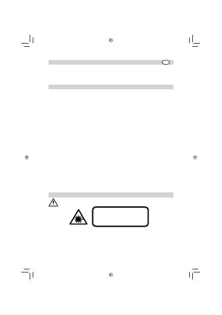
FOR YOUR SAFETY
For hazardless and safe operation, read all the user guide instructions.
LASER RADIATION AVOID DIRECT EYE EXPOSURE CLASS 3A/3R LASER PRODUCT GB
071016_01_HV101_GB.indd 5
071016_01_HV101_GB.indd 5
27.11.2007 15:13:18 Uhr
27.11.2007 15:13:18 Uhr

6
• If initial service is required, which results in the removal of the outer protective cover, removal must only be
performed by factory-trained personnel.
Caution:
Use of other than the described user and calibration tools or other procedures may result
in exposure to hazardous laser light.
Caution:
Using different than described at the HV101 user guide, may result in unsafe operation.
.
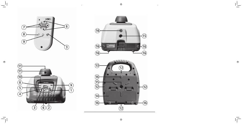
COMPONENTS
1
Power
Button
2
Battery
LED
3
Manual/Standby
Button
4
Leveling
LED
5
Manual/HI-Warning
LED
6
Up and Down Arrow Buttons
7
Left and Right arrow Buttons
8
Zone-Scan
Button
9
Rotation Control Button
10
Infrared-receiver for remote control
11
Rotor/Beam
Exit
12
Cross Mark Notches
13
Handle
14
Battery
compartment/door
15
5/8x 11 Tripod Mounts
16
Rubber
feet
How to Use the Laser System
Powering the Laser
Batteries
Installing Batteries
Open the battery door using your fi ngers, a coin or a screwdriver.
Insert batteries into the housing so that the negative poles are on the bigger battery spiral spring.
Push down on the battery door until the latch “clicks” into position.
Laser Setup
Position the laser horizontally or vertically (tripod mount and rubber feet downward!) on a stable platform, wall
mount or tripod at the desired elevation. The laser recognizes automatically whether it is used horizontally or
vertically when switched on.
Turning On/Off the Laser
Press the power button
1
to turn on the laser.
Note:
The laser always powers up in the automatic self-leveling mode. The LEDs (
2, 4
and
5
) are
turned on for 2 seconds.
The laser is level when the leveling indicator
4
is no longer fl ashing (once every second).
For the fi rst fi ve minutes after the laser self levels, the LED
4
lights solid then fl ashes every four seconds to
let you know the laser is still level.
After turning on the laser and after self-leveling, the laser starts in the last chosen mode. The „set and forget“
function turns on the laser beam while scan size, beam position and rotation speed are adjusted.
If the laser is positioned beyond it´s self-leveling range of ±8%, the laser beam, and manual and leveling
indicators fl ash simultaneously. Turn the unit off, reposition the laser within the self-leveling range and turn
it on again.
Note:
If the laser is out of its self-leveling range and remains out of it for more than 10 minutes, the
unit shuts down completely.
Note:
After the laser has been level for more than 5 minutes in horizontal mode and the rotor is
rotating at 600 rpm, the HI (height of instrument) alert activates. If the laser is disturbed (tripod
bumped, etc.) so that when it re-levels the laser beam elevation changes by more than 3 mm
(1/8 in.), the HI alert shuts down the laser and rotor, and the red LED fl ashes two times per second
(twice the manual-mode rate). To restore level, turn the laser off and on. After the laser has re-leveled,
check your initial reference elevation.
In order to switch the laser off, press the power button again.
071016_01_HV101_GB.indd 6
071016_01_HV101_GB.indd 6
27.11.2007 15:13:19 Uhr
27.11.2007 15:13:19 Uhr

7
Activating/Deactivating Standby Mode
Standby mode is a power-saving feature that conserves laser battery life.
Press and hold the laser’s or remote control’s manual button for 3 seconds to activate standby mode.
Note:
When standby mode is activated, the laser beam, rotor, self-leveling system, and LEDs shut
down, but the HI alert remains activated.
To let you know that the laser is in standby mode, the battery LED fl ashes every 4 seconds.
To deactivate standby mode and restore full operation of the laser, press and hold the laser’s or remote control’s
manual button for 3 seconds.
The laser and all other functions turn on again.
Using the Rotation Mode
The rotation control button
9
sets the laser into rotation mode. Scan mode is stopped.
Repeatedly pressing the button toggles the laser through 0, 50, 200, 600 RPM.
The laser always powers up in the last selected rotation speed.
Note:
The zone-scan button can be used to stop the beam’s rotation.
Using the Pointing Mode
Laser
If the beam’s rotation is stopped during horizontal operation, the up and down arrow buttons at the laser can
be pressed to move the beam (small line) gradually counterclockwise or clockwise (360°).
During vertical operation, the up /down arrow buttons can be used to move the small line left/right.
Remote Control
If the beam’s rotation is stopped during horizontal operation, the remote control’s left and right arrow buttons
can be pressed to move the beam gradually counterclockwise or clockwise (360°).
During vertical operation, the left /right arrow buttons can be used to move the beam counterclockwise/
clockwise.
By pressing and holding either button, the movement of the small line will be accelerated.
Note:
The fi rst 4 seconds, the beam moves in fi ne pointing speed, then it moves in course speed.
Using the Scan Mode
Pressing and releasing the zone-scan button at the laser or remote control sets the laser to scan mode.
Rotation mode is stopped.
The unit starts at an opening angle of approx. 3 degrees. Repeatedly pressing the zone-scan button increases
the angle to approx. 8, 45, 90, 180 and 0 degrees.
Pressing the up or down button at the laser or the right or left arrow button at the remote control moves the
scan zone clockwise or counterclockwise until the desired position is reached.
Note:
In self-leveling mode (horizontal), the up arrow button increases the zone-scan size (up to
180º), and the down arrow button decreases the size (down to 3º).
Note:
The rotation control button can be used to stop the scan mode.
Using the Manual Mode
Pressing the manual button on the laser or the remote control changes the laser from automatic self-leveling
mode to Manual mode. Manual mode is indicated by the fl ashing (once every second) red LED
5
.
In Manual mode (horizontal), the Y-axis can be sloped by pressing the Up- and Down-Arrow-buttons on the
laser‘s keypad or the remote control. Additionally, the X-axis can be sloped by pressing the Left- and Right-
Arrow-buttons on the remote control.
In vertical mode, the up and down arrow buttons align the laser beam to the right/left side,
and the left and right arrow buttons at the remote control adjust the slope of the laser beam.
To resume automatic self-leveling mode, press the manual button again.
Using the Y- or X-Axis Single Slope Mode
To activate the Y-axis single slope mode, press the manual button (1 second) after the up arrow button at the
laser or remote control has been pressed and released. This is indicated by the simultaneously fl ashing red
5
and green
4
LEDs (once every second).
071016_01_HV101_GB.indd 7
071016_01_HV101_GB.indd 7
27.11.2007 15:13:19 Uhr
27.11.2007 15:13:19 Uhr
Оглавление
- TABLE OF CONTENTS
- COMPONENTS
- APPLICATIONS
- CALIBRATION
- M101 WALL MOUNT
- PROTECTING THE ENVIRONMENT
- DECLARATION OF CONFORMITY
- INHALTSVERZEICHNIS
- GERÄTEELEMENTE
- ARBEITSBEISPIELE
- NIVELLIERGENAUIGKEIT
- WANDHALTERUNG M101
- GEWÄHRLEISTUNG
- SOMMAIRE
- ELEMENTS DE L’APPAREIL
- EXEMPLES DE TRAVAIL
- PRECISION DE NIVELLEMENT
- Fixation murale M101
- GARANTIE
- INDICE
- ELEMENTI DELL‘APPARECCHIO
- ESEMPI OPERATIVI
- PRECISIONE
- Fissaggio a muro M101
- GARANZIA
- ÍNDICE
- ELEMENTOS DEL APARATO
- EJEMPLOS DE TRABAJO
- PRECISIÓN DE NIVELACIÓN
- Soporte para pared M101
- GARANTÍA
- INHOUDSOPGAVE
- ONDERDELEN
- WERKVOORBEELDEN
- WATERPASNAUWKEURIGHEID
- Wandhouder M101
- GARANTIE
- INNEHÅLLSFÖRTECKNING
- APPARATELEMENT
- ARBETSEXEMPEL
- AVVÄGNINGSNOGGRANNHET
- Väggfäste M101
- MILJÖSKYDD
- Försäkran om överensstämmelse
- INDHOLDSFORTEGNELSE
- BETEGNELSER
- EKSEMPLER PÅ OPGAVER
- KONTROL AF NØJAGTIGHED
- Vægbeslag M101
- OPBEVARING OG HÅNDTERING AF LASEREN
- TEKNISKE DATA
- ÍNDICE
- ELEMENTOS DO APARELHO
- EXEMPLOS DE TRABALHOS
- EXACTIDÃO DE NIVELAÇÃO
- SUPORTE DE PAREDE M101
- GARANTIA
- INNHOLDSFORTEGNELSE
- APPARATELEMENTENE
- ARBEIDSEKSEMPLER
- NIVELLERINGSNØYAKTIGHET
- Veggholdeinnretning M101
- MILJØVERN
- Konformitetserklæring
- SISÄLTÖ
- LAITE
- KÄYTTÖESIMERKIT
- TARKKUUS
- SEINÄKIINNITYS M101
- YMPÄRISTÖNSUOJA
- Yhteensopivuusilmoitus
- ΠΙΝΑΚΑΣ ΠΕΡΙΕΧΟΜΕΝΩΝ
- ΜΕΡΗ ΣΥΣΚΕΥΗΣ
- Εφεδρικός τρόπος λειτουργίας
- ΠΑΡΑΔΕΙΓΜΑΤΑ ΕΡΓΑΣΙΑΣ
- ΑΚΡΙΒΕΙΑ ΧΩΡΟΣΤΑΘΜΗΣΗΣ
- ΠΡΟΣΤΑΣΙΑ ΤΗΣ ΣΥΣΚΕΥΗΣ
- ΕΓΓΥΗΣΗ
- CO Д EP Ж AH И E
- КОМПОНЕНТЫ
- ЭКСПЛУАТАЦИЯ
- КАЛИБРОВКА
- ЗАЩИТА ПРИБОРА
- ГАРАНТИЯ
- ЗАЯВЛЕНИЕ О СООТВЕТСТВИИ
- Service and Customer Advice
