Trimble Outdoors HV101: CALIBRATION
CALIBRATION: Trimble Outdoors HV101
9
Using the Y-Axis Single Slope Mode
1. Set up the laser over the reference point (A).
2. Look over the rotor to align the laser to the desired direction hub
in the axis that is supposed to be used in automatic self-leveling
mode. Turn the laser on the tripod until it is properly aligned.
3. Attach a receiver to a grade rod. Set the grade rod on the self-leveling
axis direction hub to check the laser’s elevation (B).
Note:
Use this HI as a reference for checking the alignment
of the laser after setting the slope for the other axis.
4. Activate the Y-axis single slope mode by pressing the manual button
(1 second) after the up arrow button at the laser or remote control
has been pressed and released.
5. Check the laser’s elevation on the slope axis directly in front of the
laser.
6. Set the grade rod on the slope axis direction hub to adjust the laser’s elevation without changing the height
of the receiver on the grade rod (C).
7. Press the up and down arrow buttons until you get an on-grade reading on the receiver.
8. Recheck the laser’s elevation in automatic self-leveling axis using the HI in step 3 (B).
If the HI has been changed, rotate the laser on the tripod until you get an on-grade reading again. Make sure,
you DON’T change the height of the receiver on the grade rod.
CALIBRATION
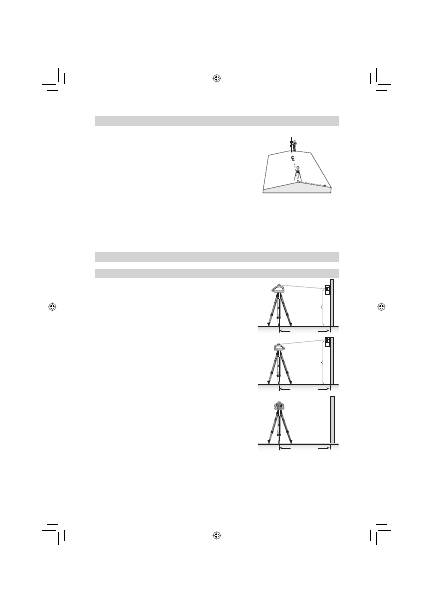
Checking Calibration of the Y- and X-Axes
1. Set up the laser 30 m (100 ft) from a wall and allow it to level.
2. Raise/lower the receiver until you get an on-grade reading for the
+Y
⬔
axis. Using the on-grade marking notch as a reference, make
a mark on the wall.
Note:
For increased precision, use the fi ne-sensitivity setting
(1.5 mm/1/16 in.) on the receiver.
3. Rotate the laser 180° (-Y axis toward the wall) and allow the laser
to re-level.
4. Raise/lower the receiver until you get an on-grade reading for the
–Y
⬔
axis. Using the on-grade marking notch as a reference, make
a mark on the wall.
5. Measure the difference between the two marks. If they differ
more than 6 mm at 30 m (1/4 inch at 100 feet), the laser needs
calibrating.
6. After checking the Y-axis, rotate the laser 90°. Repeat the above
starting with the + X axis facing the wall.
A
C
B
30 m (100 ft)
Y
1
Y+
30 m (100 ft)
-
Y
Y
2
30 m (100 ft)
x +
071016_01_HV101_GB.indd 9
071016_01_HV101_GB.indd 9
27.11.2007 15:13:20 Uhr
27.11.2007 15:13:20 Uhr
Оглавление
- TABLE OF CONTENTS
- COMPONENTS
- APPLICATIONS
- CALIBRATION
- M101 WALL MOUNT
- PROTECTING THE ENVIRONMENT
- DECLARATION OF CONFORMITY
- INHALTSVERZEICHNIS
- GERÄTEELEMENTE
- ARBEITSBEISPIELE
- NIVELLIERGENAUIGKEIT
- WANDHALTERUNG M101
- GEWÄHRLEISTUNG
- SOMMAIRE
- ELEMENTS DE L’APPAREIL
- EXEMPLES DE TRAVAIL
- PRECISION DE NIVELLEMENT
- Fixation murale M101
- GARANTIE
- INDICE
- ELEMENTI DELL‘APPARECCHIO
- ESEMPI OPERATIVI
- PRECISIONE
- Fissaggio a muro M101
- GARANZIA
- ÍNDICE
- ELEMENTOS DEL APARATO
- EJEMPLOS DE TRABAJO
- PRECISIÓN DE NIVELACIÓN
- Soporte para pared M101
- GARANTÍA
- INHOUDSOPGAVE
- ONDERDELEN
- WERKVOORBEELDEN
- WATERPASNAUWKEURIGHEID
- Wandhouder M101
- GARANTIE
- INNEHÅLLSFÖRTECKNING
- APPARATELEMENT
- ARBETSEXEMPEL
- AVVÄGNINGSNOGGRANNHET
- Väggfäste M101
- MILJÖSKYDD
- Försäkran om överensstämmelse
- INDHOLDSFORTEGNELSE
- BETEGNELSER
- EKSEMPLER PÅ OPGAVER
- KONTROL AF NØJAGTIGHED
- Vægbeslag M101
- OPBEVARING OG HÅNDTERING AF LASEREN
- TEKNISKE DATA
- ÍNDICE
- ELEMENTOS DO APARELHO
- EXEMPLOS DE TRABALHOS
- EXACTIDÃO DE NIVELAÇÃO
- SUPORTE DE PAREDE M101
- GARANTIA
- INNHOLDSFORTEGNELSE
- APPARATELEMENTENE
- ARBEIDSEKSEMPLER
- NIVELLERINGSNØYAKTIGHET
- Veggholdeinnretning M101
- MILJØVERN
- Konformitetserklæring
- SISÄLTÖ
- LAITE
- KÄYTTÖESIMERKIT
- TARKKUUS
- SEINÄKIINNITYS M101
- YMPÄRISTÖNSUOJA
- Yhteensopivuusilmoitus
- ΠΙΝΑΚΑΣ ΠΕΡΙΕΧΟΜΕΝΩΝ
- ΜΕΡΗ ΣΥΣΚΕΥΗΣ
- Εφεδρικός τρόπος λειτουργίας
- ΠΑΡΑΔΕΙΓΜΑΤΑ ΕΡΓΑΣΙΑΣ
- ΑΚΡΙΒΕΙΑ ΧΩΡΟΣΤΑΘΜΗΣΗΣ
- ΠΡΟΣΤΑΣΙΑ ΤΗΣ ΣΥΣΚΕΥΗΣ
- ΕΓΓΥΗΣΗ
- CO Д EP Ж AH И E
- КОМПОНЕНТЫ
- ЭКСПЛУАТАЦИЯ
- КАЛИБРОВКА
- ЗАЩИТА ПРИБОРА
- ГАРАНТИЯ
- ЗАЯВЛЕНИЕ О СООТВЕТСТВИИ
- Service and Customer Advice
