Stiebel Eltron FCR 18-28: INSTALLATION
INSTALLATION: Stiebel Eltron FCR 18-28
INSTALLATION
Safety
8. Appliance description
INSTALLATION
8.1 Standard delivery
Delivered with the appliance:
7. Safety
- Cable entries (supplied as loose parts depending on the ap-
pliance type)
Only a qualified contractor should carry out installation, commis-
sioning, maintenance and repair of the appliance.
- Fixing screws, corrugated washers
7.1 General safety instructions
8.2 Accessories
ENGLISH
We guarantee trouble-free function and operational reliability
Required accessories
only if the original accessories and spare parts intended for the
appliance are used.
Depending on the static pressure, safety assemblies and pressure
reducing valves are available. These type-tested safety assemblies
7.2 Instructions, standards and regulations
protect the appliance against unacceptable excess pressure.
Further accessories
Note
Observe all applicable national and regional regulations
A mating flange is available as an accessory.
and instructions.
9. Installation
7.3 Water connection and safety assembly
Note
For the installation of the appliance, the cylinder must
Note
be fitted with a mating flange (see chapter "Appliance
Carry out all water connection and installation work in
description / Accessories").
accordance with regulations.
The cylinder must be connected with water inlet and outlet pipes
Note
made from metal. Other metal parts of the cylinder that can be
The control panel must not be thermally insulated to pre-
touched and that are in contact with water must be permanently
vent any excessively high temperatures from occurring
and reliably connected with the earth conductor.
inside the control panel.
The condensate aperture in the flanged control panel
must remain open while the cylinder is thermally insulat-
The max. permissible pressure must not be exceeded (see chapter
ed so that any condensate that occurs can drip off freely.
"Specification/ Data table" and cylinder specification).
Install a type-tested safety valve in the cold water supply
Observe the required torque values during installation (see
line. For this bear in mind that, depending on the static pres-
chapter "Specification / Data table").
sure, you may also need a pressure reducing valve.
Always install the appliance horizontally with the cable en-
Size the drain so that water can drain off unimpeded when
tries facing downwards.
the safety valve is fully opened.
Always install the appliance with heating elements and a
Fit the discharge pipe of the safety valve with a constant
protective pipe arranged in parallel. For this, use the screws
downward slope and in a room free from the risk of frost.
supplied. Realign the components where necessary.
The safety valve discharge aperture must remain open to the
atmosphere.
www.stiebel-eltron.com FCR 28 | FCR 18 | 17
INSTALLATION
Commissioning
9.1 Power connection
Material losses
!
Contactors for thermostats or high limit safety cut-outs
WARNING Electrocution
must be installed outside the control panel of the flanged
Carry out all electrical connection and installation work
immersion heater. The contactors must be switched inde-
in accordance with relevant regulations.
pendently of one another by the thermostats and the high
limit safety cut-out respectively (see chapter "Specifica-
WARNING Electrocution
tion/ Wiring diagrams and connections").
Only use a permanent connection to the power supply.
Ensure that the appliance can be separated from the
If the appliance is operated with power-OFF control, you must
power supply by an isolator that disconnects all poles
install the power-OFF contact between the contactors or upstream
with at least 3mm contact separation.
of the contactor.
WARNING Electrocution
Required contactor breaking capacity:
Ensure that the appliance is earthed.
Sizing in accordance with the connected load (see chapter
"Specification/ Data table") for l
e
/ AC-1 / 70°C (thermal con-
stant current with a resistive load at an ambient temperature of
Material losses
!
up to 70°C).
Observe the type plate. The specified voltage must match
the mains voltage.
Label the contactors according to their function.
If required, mark any live components inside the control
If required, pull off the temperature selector.
panel that are supplied with power from outside.
Undo the screws at the bottom of the control panel cover and
Once connected, check that the contactors are functioning
remove the cover.
properly.
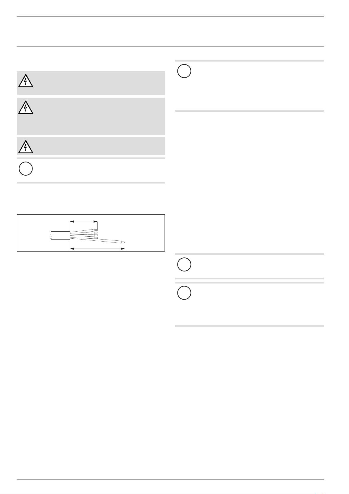
100
10. Commissioning
10.1 Commissioning
200
26�02�79�0049
Fill the system with water.
Select a cable of the cross-sectional area suited to the load
Material losses
of the appliance. Prepare the power cable, ensuring that the
!
Boiling dry destroys the thermostat, which must then
earth conductor is longer than the other conductors.
be replaced. The high limit safety cut-out must be reset.
Feed the power cable through the cable entry into the control
panel.
Material losses
Connect the required load in accordance with the wiring
!
If an indirect coil is installed in the same cylinder, limit
diagrams (see chapter "Specification/ Wiring diagrams and
the maximum temperature for this appliance to the maxi-
connections").
mum temperature for the flanged immersion heater. This
Fit the control panel cover.
prevents the high limit safety cut-out of the flanged im-
If required, push the temperature selector back on.
mersion heater from responding.
Appliance type with dual circuit operation: Use a ballpoint
pen to mark the selected connected load and voltage on the
Appliance handover
type plate.
Explain the appliance function to users and familiarise them
with its operation.
Make users aware of potential dangers.
Hand over these instructions.
10.2 Recommissioning
See chapter "Commissioning".
18 | FCR 28 | FCR 18 www.stiebel-eltron.com
INSTALLATION
Settings
11. Settings
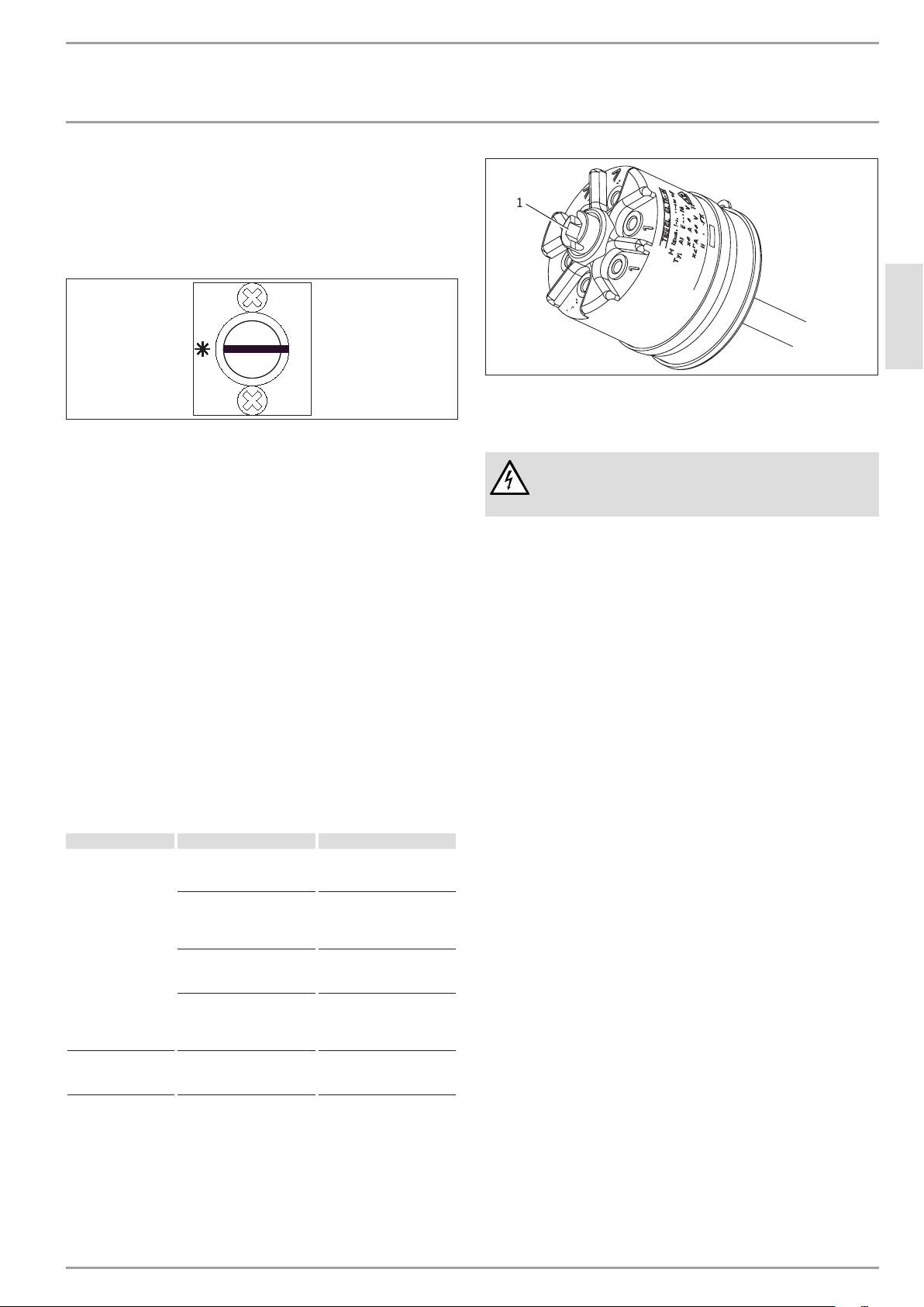
1
11.1 Temperature
Appliance type with temperature selector inside the control
panel
35°C
ENGLISH
60°C
26�02�79�0015
1 High limit safety cut-out reset button
85°C
26�02�79�0028
13. Maintenance
Factory setting: 60°C
WARNING Electrocution
11.2 Limiting the temperature selection
Before any work on the appliance, disconnect all poles
Appliance type with external temperature selector
from the power supply.
You can adjust the temperature selection limitation beneath the
temperature selector.
13.1 Checking the safety assembly
Factory setting: 60°C
Check the safety assembly regularly.
Set the temperature selector to "cold" and isolate the appli-
ance from the power supply.
13.2 Descaling the flanged immersion heater
Remove the temperature selector and the control panel
Descale the flanged immersion heater only after it has been
cover.
removed.
Loosen the two screws from the outside and pull the thermo-
stat down to remove.
13.3 Replacing the heating elements and protective
Once you have removed the limiter disc from the thermostat
pipe
axis, the maximum temperature can be reached.
When installing heating elements or a protective pipe, en-
Tighten the thermostat screws again and replace the tem-
sure that the components are electrically isolated from the
perature selector and control panel cover.
flange.
12. Troubleshooting
Fault Cause Remedy
The water does not
The high limit safety cut-
Replace the thermostat and
heat up.
out has responded because
press the high limit safety
the controller is faulty.
cut-out reset button.
The high limit safety cut-
Press the reset button.
out has responded because
the temperature has fallen
below -15°C.
A heating element is faulty.
Replace the heating ele-
ment or flanged immersion
heater.
The high limit safety cut-
Limit the maximum tem-
out has responded because
perature of the indirect
an indirect coil in the same
coil.
cylinder is set too high.
The safety valve drips
The valve seat is contami-
Clean the valve seat.
when the heating is
nated.
switched off.
www.stiebel-eltron.com FCR 28 | FCR 18 | 19
INSTALLATION
Specication
14. Specification
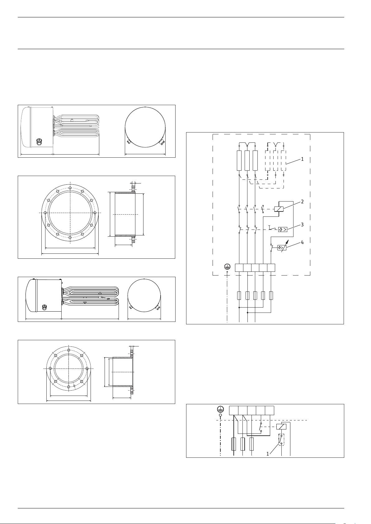
14.1 Dimensions, immersion depths and connections
FCR 28
225
325
280
D0000020344D0000020344
Mating flange FCR 28
14
Ø 219
Ø 205
83
245
280
26�02�79�0013
FCR 18
20 | FCR 28 | FCR 18 www.stiebel-eltron.com
320225
210
14.2 Wiring diagrams and connections
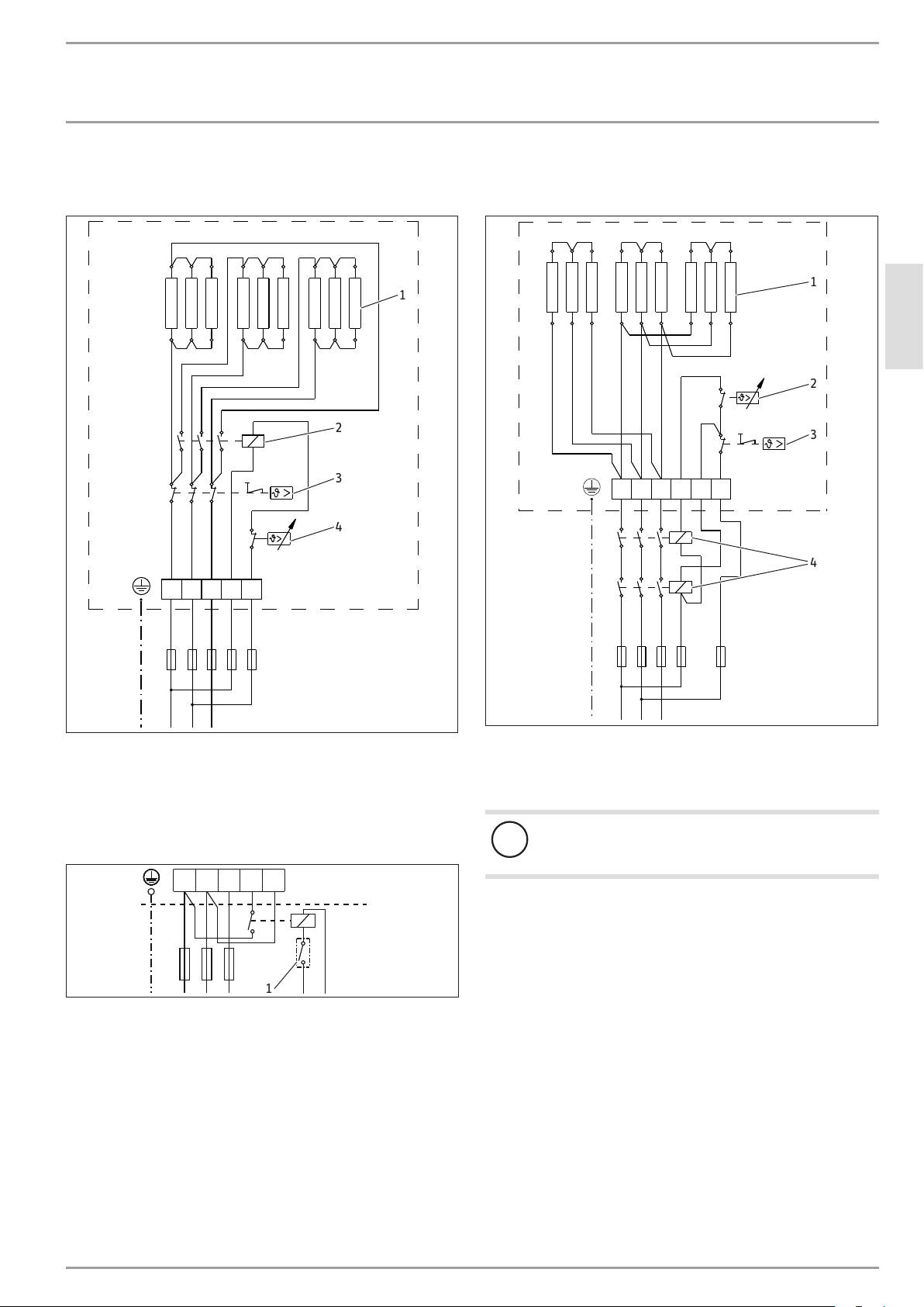
14.2.1 Single circuit operation
FCR 28/120, part number 000694
FCR 28/180, part number 000695
FCR 18/60, part number 000691
FCR 18/90, part number 000692
6, 9, 12, 18 kW, 3/PE ~ 400 V
1
2
3
4
L1
L3L2
4
5
D0000032232
26�02�79�0016
Mating flange FCR 18
1 Heating element
6 kW connected load: 3 x 2 kW
10
9 kW connected load: 3 x 3 kW
12 kW connected load: 6 x 2 kW
18 kW connected load: 6 x 3 kW
2 Contactor
3 High limit safety cut-out
Ø 120
Ø 110
4 Thermostat
Connection example for single circuit operation with power-
150
73
OFF contact
180
26�02�79�0014
L1
4
5L3L2
1
26�02�79�0050
1 Power-OFF contact, installed by the heating contractor
INSTALLATION
Specication
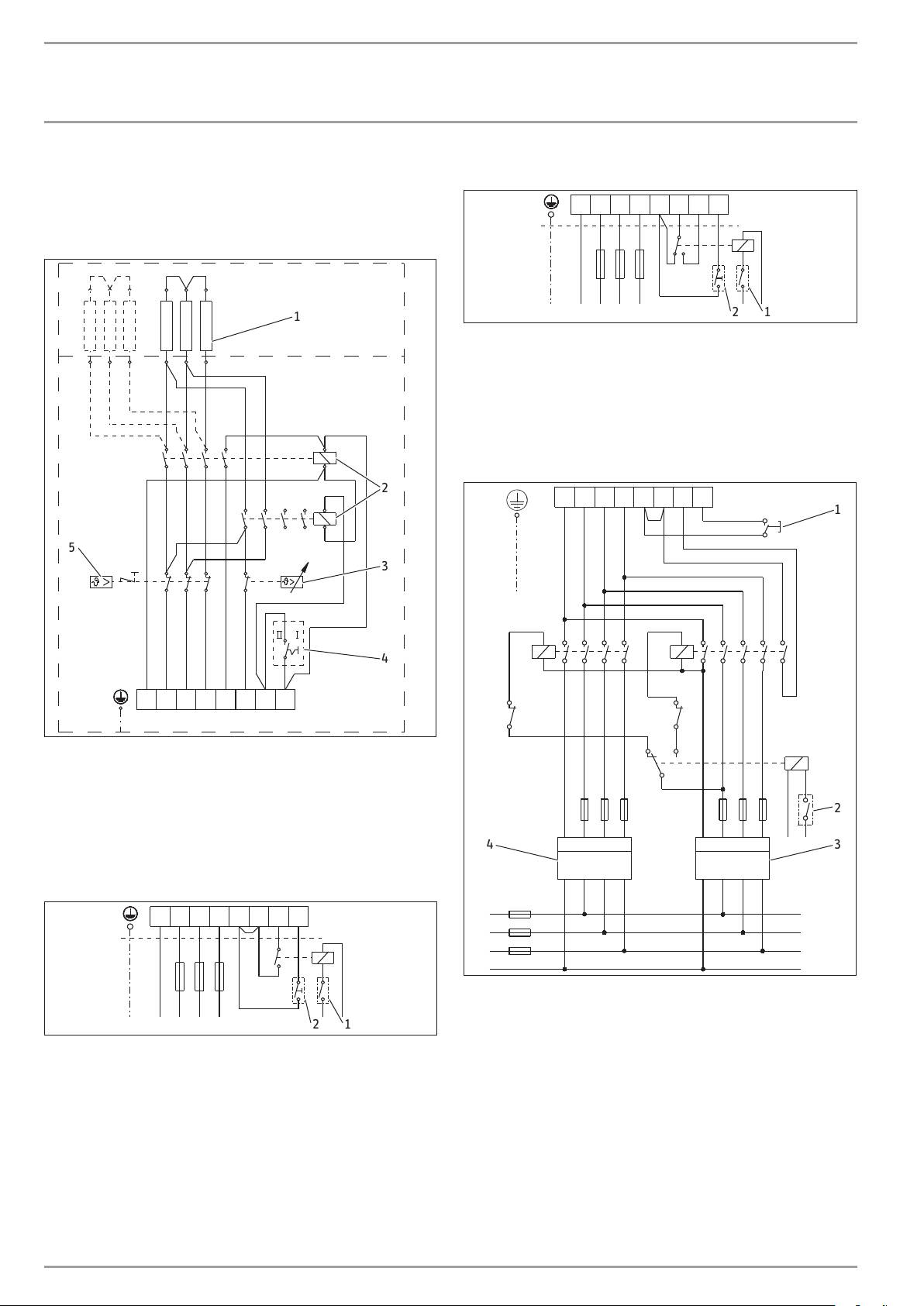
FCR 28/270, part number 000696
FCR 28/360, part number 001502
27 kW, 3/PE ~ 400 V
36 kW, 3/PE ~ 400 V
1
1
ENGLISH
2
2
3
3
L1
L3L2
4
5
6
4
4
L1
L3L2
4
5
26�02�79�0017
26�02�79�0018
1 Heating element 4 kW
1 Heating element 3 kW
2 Thermostat
2 Contactor
3 High limit safety cut-out
3 High limit safety cut-out
4 Contactor, installed by the heating contractor
4 Thermostat
Connection example for single circuit operation with power-
Material losses
OFF contact
!
When connecting the contactors, please observe chapter
"Installation / Power connection".
L1
4
5L3L2
1
26�02�79�0050
1 Power-OFF contact, installed by the heating contractor
www.stiebel-eltron.com FCR 28 | FCR 18 | 21
INSTALLATION
Specication
14.2.2 Dual circuit / single circuit operation 3/N/PE ~ 400 V
Connection example for dual circuit operation, version 2
FCR 28/120, part number 071332
L1N
1
2L3L2
3
4
FCR 28/180, part number 071333
6/12 kW, 12/12 kW, 9/18 kW, 18/18 kW
12
26�02�79�0047
1
1 Power-OFF contact, installed by the heating contractor
2 Pushbutton for controlling the rapid heat-up function re-
motely, installed by the heating contractor
With standard heating in switch position II reheating is also possi-
ble during off-peak tariff periods. With standard heating in switch
position I, reheating is not possible.
Connection example for dual meter reading
2
L1N
1
2L3L2
3
4
1
5
3
K1
K2
4
L1N
1
2L3L2
3
4
K2
K1
26�02�79�0022
1 Heating element
12 kW connected load: 3 x 4 kW
18 kW connected load: 6 x 3 kW
2 Contactor
2
3 Thermostat
4 Circuit breaker I / II
34
5 High limit safety cut-out
Connection example for dual circuit operation, version 1
L1N
1
2L3L2
3
4
26�02�79�0020
K1 Contactor 1, installed by the heating contractor
K2 Contactor 2, installed by the heating contractor
12
26�02�79�0019
1 Pushbutton for controlling the rapid heat-up function re-
motely, installed by the heating contractor
1 Power-OFF contact, installed by the heating contractor
2 Power-OFF contact, installed by the heating contractor
2 Pushbutton for controlling the rapid heat-up function re-
3 Off-peak tariff
motely, installed by the heating contractor
4 Peak tariff
With standard heating in switch position I and II, reheating is also
possible during off-peak tariff periods.
22 | FCR 28 | FCR 18 www.stiebel-eltron.com
INSTALLATION
Specication
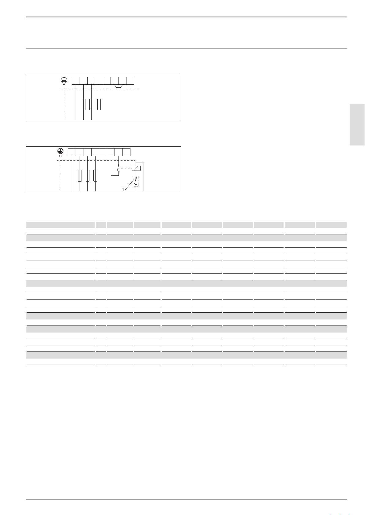
Connection example for single circuit operation
L1N
1
2L3L2
3
4
26�02�79�0021
Connection example for single circuit operation with power-
ENGLISH
OFF contact
L1N
1
2L3L2
3
4
1
26�02�79�0051
1 Power-OFF contact, installed by the heating contractor
14.3 Specification
FCR 18/60 FCR 18/90 FCR 28/120 FCR 28/120 FCR 28/180 FCR 28/180 FCR 28/270 FCR 28/360
000691 000692 071332 000694 071333 000695 000696 001502
Electrical data
Connected load ~ 400 V kW 6 9 6/12 12 9/18 18 27 36
Rated voltage V 400 400 400 400 400 400 400 400
Phases 3/PE 3/PE 3/N/PE 3/PE 3/N/PE 3/PE 3/PE 3/PE
Frequency Hz 50/60 50 50 50 50 50 50 50/60
Single circuit operating mode X X X X X X
Dual circuit operating mode X X
Application limits
Temperature setting range °C 35-85 35-85 35-85 35-85 35-85 35-85 35-85 35-85
Max. permissible pressure MPa 1.0 1.0 1.0 1.0 1.0 1.0 1.0 1.0
Minimum cylinder diameter mm 450 450 550 450 550 450 450 550
Minimum cylinder volume l 200 200 300 200 300 200 200 300
Versions
IP rating IP24 IP24 IP24 IP24 IP24 IP24 IP24 IP24
Dimensions
External flange diameter mm 180 180 280 280 280 280 280 280
Immersion depth mm 325 325 450 325 450 325 325 450
Torque Nm 55 55 80 80 80 80 80 80
Weights
Weight kg 13.5 15.5 13 13 13 13 13 17
www.stiebel-eltron.com FCR 28 | FCR 18 | 23

Guarantee
GUARANTEE
environment and recyclinG
ENVIRONMENT AND RECYCLING
Guarantee | environment and recyclinG
Warranty
The warranty conditions of our German companies do not
apply to appliances acquired outside of Germany. In countries
where our subsidiaries sell our products, it is increasingly the
case that warranties can only be issued by those subsidiaries.
Such warranties are only granted if the subsidiary has issued
its own terms of warranty. No other warranty will be granted.
We shall not provide any warranty for appliances acquired in
countries where we have no subsidiary to sell our products.
This will not aect warranties issued by any importers.
Environment and recycling
We would ask you to help protect the environment. After use,
dispose of the various materials in accordance with national
regulations.
24 | FCR 28 | FCR 18 www.stiebel-eltron.com
