Bowers & Wilkins ASW608: инструкция
Раздел: Бытовая, кухонная техника, электроника и оборудование
Тип: Микрофон
Инструкция к Микрофону Bowers & Wilkins ASW608
II11427 Issue 5
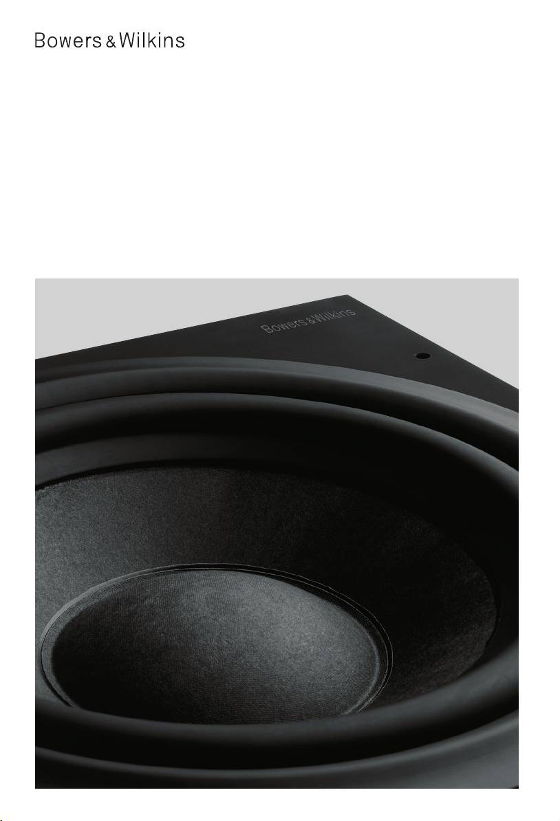
600 Series
ASW608
ASW610
ASW610XP
Owner’s Manual
Kevlar is a registered trademark of DuPont.
B&W Group (UK Sales)
B&W Group Ltd
Nautilus is a trademark of B&W Group Ltd.
T +44 1903 221 500
Dale Road
Copyright © B&W Group Ltd. E&OE
E uksales@bwgroup.com
Worthing West Sussex
Printed in China.
BN11 2BH England
B&W Group North America
T +1 978 664 2870
T +44 (0) 1903 221800
E marketing@bwgroupusa.com
F +44 (0) 1903 221801
info@bwgroup.com
B&W Group Asia Ltd
www.bowers-wilkins.com
T +852 2 869 9916
E info@bwgroup.hk
Figure 1 (ASW608/ASW610)
Figure 2 (ASW608/ASW610)
Processor
1
Front Amplifier
Line Outputs
Input
Speaker Outputs
2
Subwoofer
RearCentreFront
L
LR
R
3
SPEAKERS
4
Centre Channel Amplifier
Rear Amplifier
Input
Speaker Outputs
Input
Speaker Outputs
5
L
LR
L
LR
6
R
R
7
SPEAKERS
8
9
Subwoofer
SPEAKER
13
10
14
11
12
Figure 1 (ASW610XP)
Figure 2 (ASW610XP)
Processor
Front Amplifier
Line Outputs
1
Input
Speaker Outputs
Subwoofer
RearCentreFront
L
LR
2
R
3
SPEAKERS
Centre Channel Amplifier
Rear Amplifier
4
Input
Speaker Outputs
Input
Speaker Outputs
5
L
LR
L
LR
6
R
R
7
8
SPEAKERS
9
10
Subwoofer
SPEAKER
11
13
14
12
ASW6xXP OM Cover Iss5.indd 1-3 31/7/08 11:03:47
II11427 Issue 5
600 Series
ASW608
ASW610
ASW610XP
Owner’s Manual
Kevlar is a registered trademark of DuPont.
B&W Group (UK Sales)
B&W Group Ltd
Nautilus is a trademark of B&W Group Ltd.
T +44 1903 221 500
Dale Road
Copyright © B&W Group Ltd. E&OE
E uksales@bwgroup.com
Worthing West Sussex
Printed in China.
BN11 2BH England
B&W Group North America
T +1 978 664 2870
T +44 (0) 1903 221800
E marketing@bwgroupusa.com
F +44 (0) 1903 221801
info@bwgroup.com
B&W Group Asia Ltd
www.bowers-wilkins.com
T +852 2 869 9916
E info@bwgroup.hk
Figure 1 (ASW608/ASW610)
Figure 2 (ASW608/ASW610)
Processor
1
Front Amplifier
Line Outputs
Input
Speaker Outputs
2
Subwoofer
RearCentreFront
L
LR
R
3
SPEAKERS
4
Centre Channel Amplifier
Rear Amplifier
Input
Speaker Outputs
Input
Speaker Outputs
5
L
LR
L
LR
6
R
R
7
SPEAKERS
8
9
Subwoofer
SPEAKER
13
10
14
11
12
Figure 1 (ASW610XP)
Figure 2 (ASW610XP)
Processor
Front Amplifier
Line Outputs
1
Input
Speaker Outputs
Subwoofer
RearCentreFront
L
LR
2
R
3
SPEAKERS
Centre Channel Amplifier
Rear Amplifier
4
Input
Speaker Outputs
Input
Speaker Outputs
5
L
LR
L
LR
6
R
R
7
8
SPEAKERS
9
10
Subwoofer
SPEAKER
11
13
14
12
ASW6xXP OM Cover Iss5.indd 1-3 31/7/08 11:03:47
TRIM FOLD FOLD
Owner details
Title, first name, surname
Address
Town, postcode, country
e-mail address
Product details
Model
Serial number
Date of purchase
Dealer details
Dealer name
Address
Town, postcode, country
e-mail address
Dealer stamp
Figure 1 (ASW608/ASW610)
Figure 2 (ASW608/ASW610)
Processor
1
Front Amplifier
Line Outputs
Input
Speaker Outputs
2
Subwoofer
RearCentreFront
L
LR
R
3
SPEAKERS
4
Centre Channel Amplifier
Rear Amplifier
Input
Speaker Outputs
Input
Speaker Outputs
5
L
LR
L
LR
6
R
R
7
SPEAKERS
8
9
Subwoofer
SPEAKER
13
10
14
11
12
Figure 1 (ASW610XP)
Figure 2 (ASW610XP)
Processor
Front Amplifier
Line Outputs
1
Input
Speaker Outputs
Subwoofer
RearCentreFront
L
LR
2
R
3
SPEAKERS
Centre Channel Amplifier
Rear Amplifier
4
Input
Speaker Outputs
Input
Speaker Outputs
5
L
LR
L
LR
6
R
R
7
8
SPEAKERS
9
10
Subwoofer
SPEAKER
11
13
14
12
ASW6xXP OM Cover Iss5.indd 4-6 31/7/08 11:03:49
1
7276 608_610_610XP manual.qxd 8/12/08 12:11 Page 1
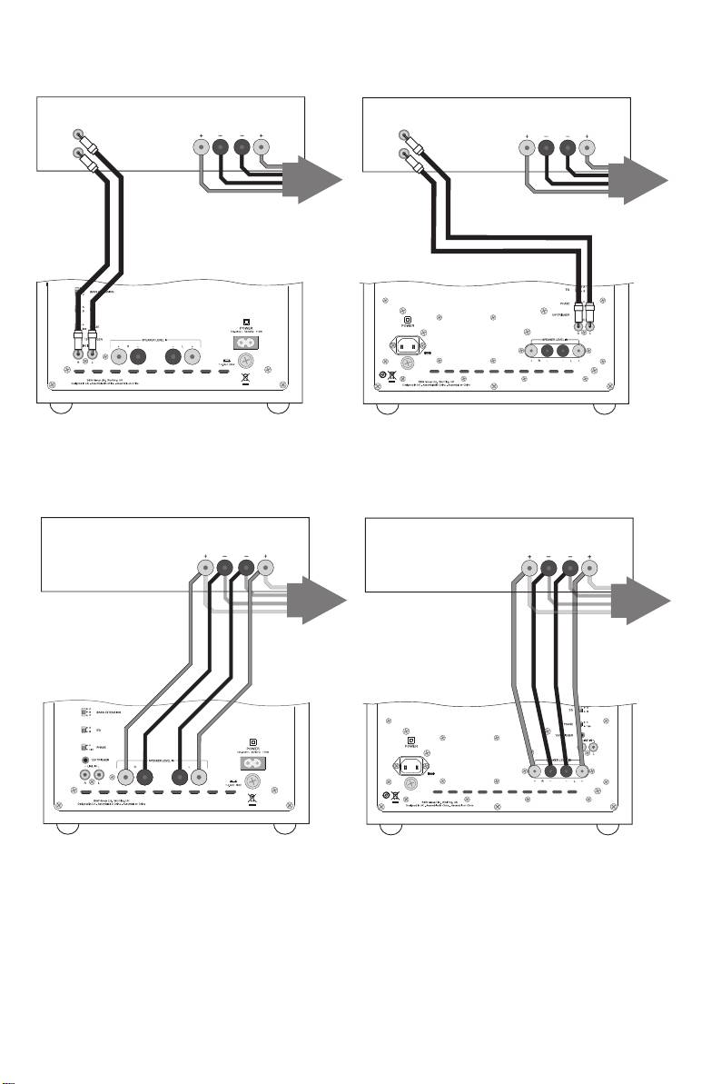
Figure 3 (ASW608/ASW610)
Figure 3 (ASW610XP)
Processor
Processor
Speaker Outputs
Speaker Outputs
Subwoofer
Front
Rear
Subwoofer
Front
Rear
LR
LR
LR
LR
SPEAKERS
SPEAKERS
Subwoofer
Subwoofer
Figure 4 (ASW608/ASW610)
Figure 4 (ASW610XP)
Processor
Processor
Speaker Outputs
Speaker Outputs
Front
Rear
Front
Rear
LR
LR
LR
LR
SPEAKERS
SPEAKERS
Subwoofer
Subwoofer
2
7276 608_610_610XP manual.qxd 8/12/08 12:11 Page 2
Figure 5 (ASW608/ASW610)
Figure 5 (ASW610XP)
Integrated Amplifier
Integrated Amplifier
Speaker OutputsLine Out
Speaker OutputsLine Out
LR
LR
L
L
R
R
SPEAKERS
SPEAKERS
Subwoofer
Subwoofer
Figure 6 (ASW608/ASW610)
Figure 6 (ASW610XP)
Integrated Amplifier
Integrated Amplifier
Speaker Outputs
Speaker Outputs
LR
LR
SPEAKERS
SPEAKERS
Subwoofer
Subwoofer
3
7276 608_610_610XP manual.qxd 8/12/08 12:11 Page 3
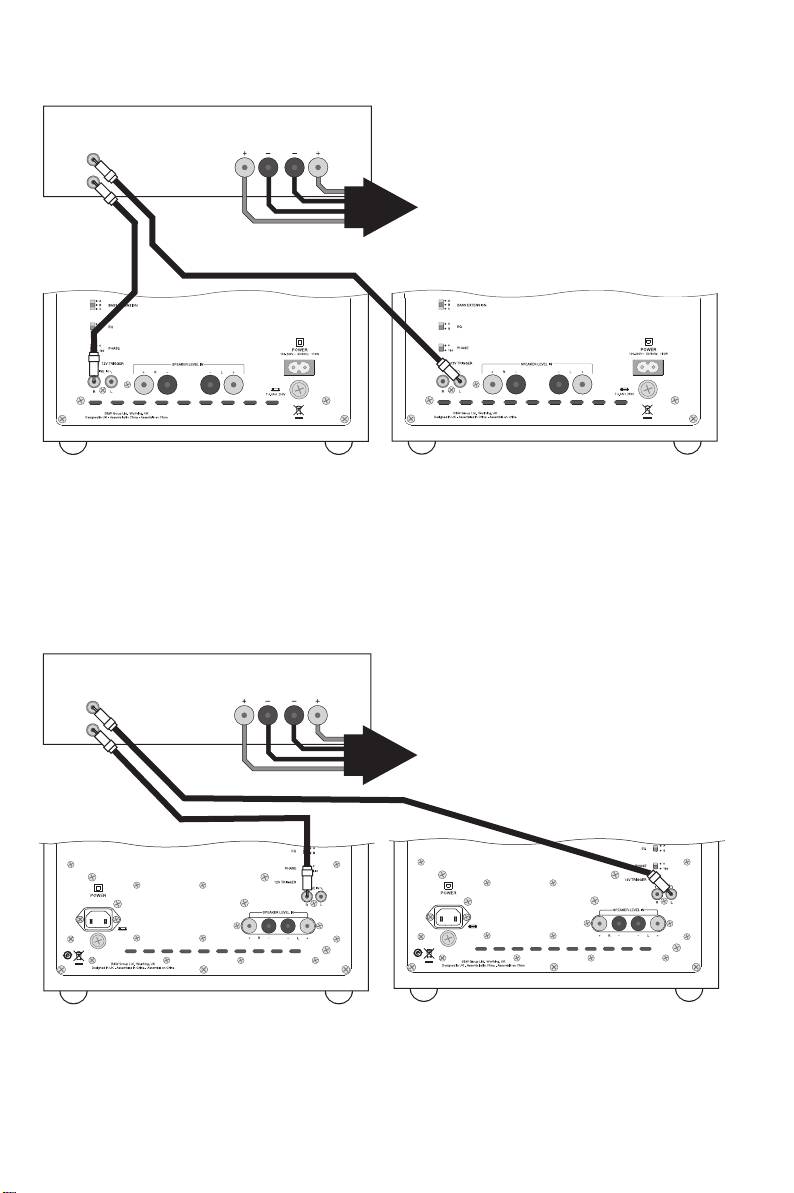
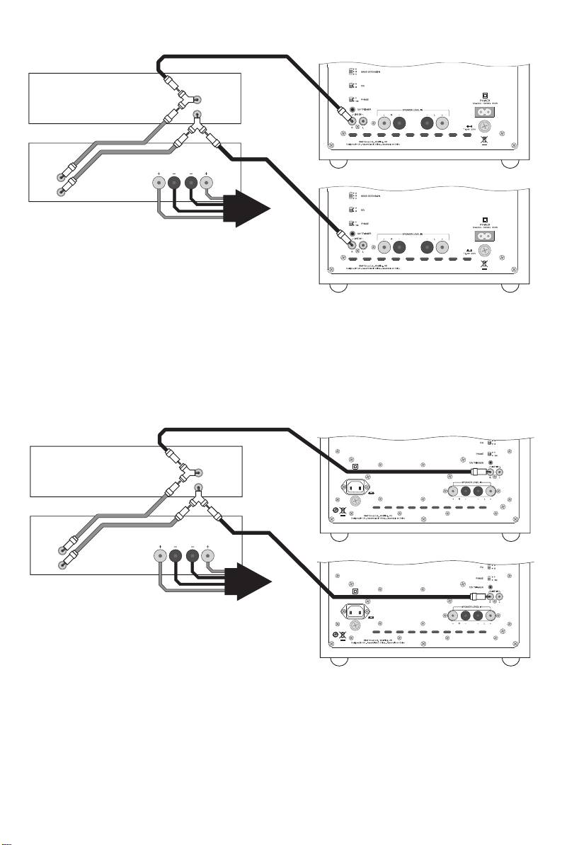
Figure 7 (ASW608/ASW610)
Integrated Amplifier
Speaker OutputsLine Level Outputs
LR
L
R
SPEAKERS
Right Subwoofer
Left Subwoofer
Figure 7 (ASW610XP)
Integrated Amplifier
Speaker OutputsLine Level Outputs
LR
L
R
SPEAKERS
Right Subwoofer
Left Subwoofer
4
7276 608_610_610XP manual.qxd 8/12/08 12:11 Page 4
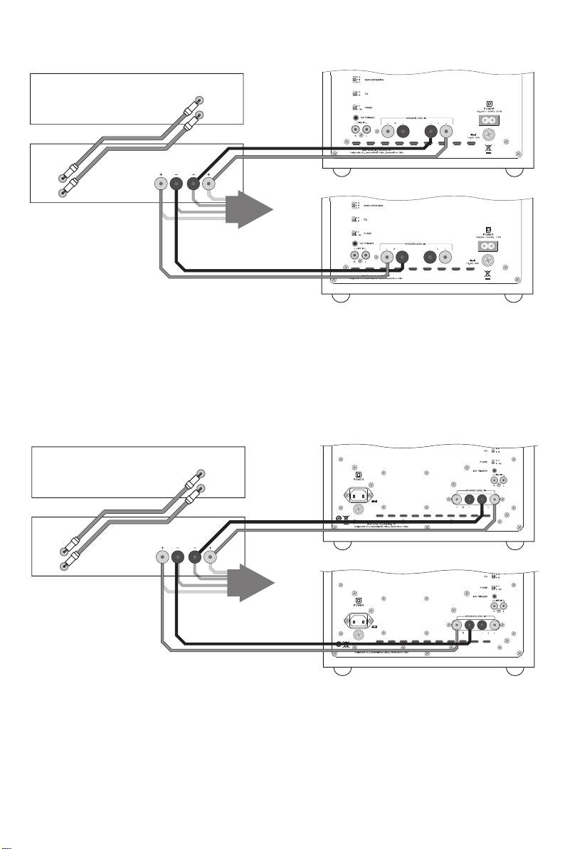
Figure 8 (ASW608/ASW610)
Integrated Amplifier
Outputs
LR
SPEAKERS
Right Subwoofer Left Subwoofer
Figure 8 (ASW610XP)
Integrated Amplifier
Outputs
LR
SPEAKERS
Right Subwoofer Left Subwoofer
5
7276 608_610_610XP manual.qxd 8/12/08 12:11 Page 5
Figure 9 (ASW608/ASW610)
Pre-Amplifier
Line Out
L
Subwoofer
R
Power Amplifier
Speaker OutputsLine In
LR
L
R
SPEAKERS
Figure 10 (ASW608/ASW610)
Pre-Amplifier
Line Out
L
Subwoofer
R
Power Amplifier
Speaker OutputsLine In
LR
L
R
SPEAKERS
Figure 9 (ASW610XP)
Pre-Amplifier
Line Out
L
Subwoofer
R
Power Amplifier
Speaker OutputsLine In
LR
L
R
SPEAKERS
Figure 10 (ASW610XP)
Pre-Amplifier
Line Out
L
Subwoofer
R
Power Amplifier
Speaker OutputsLine In
LR
L
R
SPEAKERS
6
7276 608_610_610XP manual.qxd 8/12/08 12:11 Page 6
Figure 11 (ASW608/ASW610)
Left Subwoofer
Pre-Amplifier
Line Out
L
R
Power Amplifier
Speaker OutputsLine In
LR
L
Right Subwoofer
R
SPEAKERS
Figure 11 (ASW610XP)
Left Subwoofer
Pre-Amplifier
Line Out
L
R
Power Amplifier
Speaker OutputsLine In
LR
L
Right Subwoofer
R
SPEAKERS
7
7276 608_610_610XP manual.qxd 8/12/08 12:11 Page 7
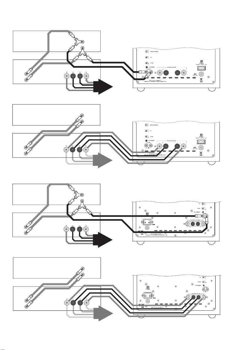
Figure 12 (ASW608/ASW610)
Left Subwoofer
Pre-Amplifier
Line Out
L
R
Power Amplifier
Speaker OutputsLine In
LR
L
Right Subwoofer
R
SPEAKERS
Figure 12 (ASW610XP)
Left Subwoofer
Pre-Amplifier
Line Out
L
R
Power Amplifier
Speaker OutputsLine In
LR
L
Right Subwoofer
R
SPEAKERS
Contents
English
Русский
Owner’s Manual............9
Руководство по
Limited Warranty.........13
эксплуатации ............59
Ограниченная
Français
гарантия....................65
Manuel d’utilisation .....14
Garantie limitée...........20
"esky
Návod k pouãití..........66
Deutsch
Záruka .......................71
Bedienungsanleitung...21
Garantie .....................26
Magyar
Használati útmutató ...72
Español
Korlátozott garancia ..77
Manual de
instrucciones ..............27
Polski
Garantía limitada.........33
Instrukcja
uÃytkownika ...............78
Português
Gwarancja .................82
Manual do utilizador....34
Garantia limitada.........39
.....................83
Italiano
.......................88
Manuale di istruzioni ...40
Garanzia limitata .........45
.......................89
Nederlands
.......................92
Handleiding ................46
Garantie .....................50
.......................93
Ελληνικά
.......................96
Οδηγίεσ Χρήσεωσ ....51
Περιορισµένη
εγγύηση....................58
EU Declaration of
Conformity..................97
Technical
Specifications......98–100
8
7276 608_610_610XP manual.qxd 8/12/08 12:11 Page 8
