Yamaha RX-497: Rear panel
Rear panel: Yamaha RX-497
Table of contents
- CAUTION: READ THIS BEFORE OPERATING YOUR UNIT.
- CONTENTS
- FEATURES SUPPLIED ACCESSORIES
- CONTROLS AND FUNCTIONS
- CONTROLS AND FUNCTIONS
- Front panel display
- Rear panel
- Remote control
- CONTROLS AND FUNCTIONS
- Installing batteries in the remote control Using the remote control
- CONNECTIONS
- Connecting speakers
- Connecting the AM and FM antennas
- Connecting the AM loop antenna
- Connecting the power supply cord Turning on and off this unit
- PLAYING AND RECORDING Playing a source
- Adjusting the tonal quality
- Recording a source
- Using the sleep timer
- Muting the sound output
- FM/AM TUNING Automatic tuning
- Manual tuning
- Automatic preset tuning
- Customized automatic preset tuning
- Manual preset tuning
- Selecting preset stations Exchanging preset stations
- RADIO DATA SYSTEM (EUROPE MODEL ONLY) Receiving Radio Data System stations Changing the Radio Data System mode
- PTY SEEK function
- EON function
- ADVANCED SETUP Changing the ADVANCED SETUP menu parameters
- Switching the remote control ID
- ZONE 2 Connecting the Zone 2 components
- Controlling Zone 2
- REMOTE CONTROL FEATURES Control area
- Controlling other components
- Setting remote control codes
- General TROUBLESHOOTING
- Tuner
- Remote control
- SPECIFICATIONS
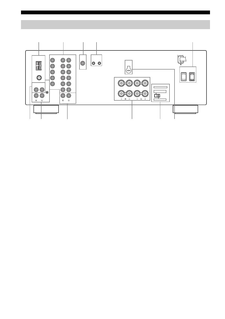
CONTROLS AND FUNCTIONS
6
1
Antenna terminals
Connect FM and AM antennas.
See page 12 for connections information.
2
AUDIO/VIDEO jacks
Connect audio and video components.
See page 10 for connection information.
3
SUB WOOFER OUTPUT jack
Connect a subwoofer with built-in amplifier.
4
REMOTE jacks
These jacks are used to input/output remote control
signals.
See page 31 for connection information.
5
AC OUTLET(S) (SWITCHED)
Use to supply power to your other audio and video
components.
See page 14 for details.
6
CD jacks
Connect a CD player.
See page 10 for connection information.
7
PHONO jacks and GND terminal
Connect a turntable.
See page 10 for connection information.
8
ZONE 2 jacks
Connect a Zone 2 component.
See page 31 for connection information.
9
SPEAKERS terminals
Connect speakers.
See page 11 for connection information.
0
IMPEDANCE SELECTOR switch
Switches the impedance setting.
See page 11 for details.
■
Asia and General models only
A
VOLTAGE SELECTOR
VOLTAGE SELECTOR on the rear panel of this unit must
be set for your local main voltage BEFORE plugging the
power supply cord into the AC wall outlet.
Voltages are as follows:
Asia model ......................... AC 220/230–240 V, 50/60 Hz
General model...... AC 110/120/220/230–240 V, 50/60 Hz
Rear panel
GND
AM
ANT
FM
ANT
75
Ω
UNBAL.
DVD
DTV/
CBL
IN
(PLAY)
IN
(PLAY)
OUT
(REC)
OUT
(REC)
MD/TAPE
ZONE 2
MONITOR
OUT
VCR
DVD
DTV/
CBL
IN
OUT
VCR
AUDIO
VIDEO
TUNER
AUDIO
GND
OUTPUT
REMOTE
CD
PHONO
OUTPUT
IN
OUT
SUB
WOOFER
A OR B: 4
Ω
MIN. /SPEAKER
A + B: 8
Ω
MIN. /SPEAKER
A OR B: 8
Ω
MIN. /SPEAKER
IMPEDANCE SELECTOR
SET BEFORE POWER ON
SELECTEUR D'IMPEDANCE
SPEAKERS
A
B
AC OUTLETS
SWITCHED
VOLTAGE
SELECTOR
6
0
A
7
9
1
2
3
4
5
8
(General model)
